Table of Contents
Advertisement
Quick Links
Assembly Instructions
OLAx-1... Oil+Air lubrication unit
for lubrication of spindle bearings, linear guides, rack pinions, chains, and assembly processes
Created on:
05-05-2022
Document no.:
951-170-241-EN
Version:
01
Read these instructions before
installation or start-up of the
product and keep them readily
available for later consultation!
Advertisement
Table of Contents

Related Manuals for SKF OLA 1 Series


Summary of Contents for SKF OLA 1 Series
- Page 1 Assembly Instructions OLAx-1... Oil+Air lubrication unit for lubrication of spindle bearings, linear guides, rack pinions, chains, and assembly processes Created on: 05-05-2022 Document no.: 951-170-241-EN Version: Read these instructions before installation or start-up of the product and keep them readily available for later consultation!
-
Page 2: Directive 2006/42/Ec, Appendix Ii Part 1 B
The special technical documents were prepared following Annex VII part B. Upon justifiable request, these special technical documents can be forwarded electronically to the respective national authorities. The authorized company for the compilation of the technical documentation is SKF (U.K.) Limited, 2 Canada Close, Banbury, Oxfordshire, OX16 2RT, GBR. - Page 3 Appendix to Declaration of Incorporation in accordance with 2006/42/EC, Annex II, No. 1 B Description of the essential health and safety requirements according to 2006/42/EC, Annex I, which have been applied and fulfilled: Table 1 Appendix to Declaration of Incorporation No.: Essential health and safety requirement Applicable:...
-
Page 4: Masthead
Training www.skf.com/lubrication We conduct detailed training in order to enable maximum safety and efficiency. We recommend taking advantage of this training. Berlin Plant For further information, contact your authorized SKF dealer or Motzener Strasse 35/37 the manufacturer. 12277 Berlin Germany Tel. -
Page 5: Table Of Contents
5.5 Storage conditions for products filled with lubricant ..24 Table of contents 5.5.1 Storage period up to 6 months ......24 5.5.2 Storage period between 6 and 18 months ..24 Original EC Declaration of Incorporation in accordance with 5.5.3 Storage period more than 18 months .... - Page 6 13.1 Temporary shutdown ............55 13.2 Permanent shutdown, disassembly ........ 55 13.3 Disposal ................55 14. Spare parts................56 14.1 General ................56 14.2 MKX gear pump unit ............58 14.3 Accessories ................59 15. Appendix ..................68 15.1 China RoHS Table .............. 68...
-
Page 7: Safety Alerts, Visual Presentation, And Layout
1. Instruction steps: These indicate a chronological sequence Safety alerts, visual of instruction steps. The numbers of the steps are in bold and are followed by a period. If a new activity follows, the presentation, and layout numbering starts again at “1.” –... -
Page 8: Safety Instructions
Only • If protective and safety equipment has to be dismantled, it original SKF spare parts and SKF accessories may be used. must be reassembled immediately after finishing the work, • Any unclear points regarding proper condition or correct and then checked for correct function. -
Page 9: Foreseeable Misuse
1.6 Foreseeable misuse NOTE Any usage of the product other than as specified in this manual In accordance with the results of the workstation risk is strictly prohibited. Particularly prohibited are: assessment, additional labels (e.g., warnings, safety signs, • Use of non-specified consumables, contaminated lubricants, prohibition signs, or labels in accordance with CLP/GHS) are or lubricants with air inclusions. -
Page 10: Note On Low Voltage Directive
• 2011/65/EU Directive on the restriction of the use of certain • Unauthorized persons must be kept away hazardous substances in electrical and electronic equipment • Mark and secure the work area (RoHS II) • Cover adjacent live parts • Dry any wet, slippery surfaces or cover them appropriately •... -
Page 11: Residual Risks
1.20 Residual risks Table 2 Residual risks Residual risk Possible in lifecycle Avoidance / Remedy Lubricant reservoir of the gear pump • Perform filling of the lubricant reservoir carefully and unit overflowing due to overfilling stop once the “MAX” mark on the lubricant reservoir is reached Risk of slipping due to contamination of B C D E F G H K •... -
Page 12: Lubricants
• Always use SKF lubrication greases, if possible. These are optimally suited for use in lubrication systems. • Do not mix lubricants. This may have unforeseeable effects on... -
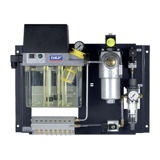
Page 13: Overview, Functional Description
3. Overview, functional description 3.1 Overview Fig. 3 Maximum configuration of the Oil+Air lubrication unit Legend to Figure 3: Gear pump unit without control unit (optionally with control Filler neck unit) Pressure gauge for oil pressure Dirt indicator for oil filter (visual/electrical) Oil filter housing with oil filter Pressure switch for minimum air pressure Compressed air regulating valve... -
Page 14: General
3.2 General 3.5 Design SKF Oil+Air lubrication units are total loss lubrication systems Fig. 4 which are used in centralized lubrication for minimal quantity lubrication of oils. Oil+Air lubrication units are employed in a wide range of areas of application. A few areas of application for Oil+Air Lubrication units are: •... -
Page 15: Functional Description
In the maximum configuration, an Oil+Air lubrication unit is The bearing is thus continuously supplied with a minimum flow comprised of the following components; see also section 3.6.1 of lubricant and air. The air flow introduced creates Hydraulic diagram of an Oil+Air lubrication unit: overpressure in the bearing assembly and prevents the ingress •... -
Page 16: Hydraulic Diagram Of An Oil+Air Lubrication Unit
3.6.1 Hydraulic diagram of an Oil+Air lubrication unit Fig. 5 Oil+Air hydraulic diagram Legend to Figure 5: Filler neck Level switch Gear pump unit without control unit Gear pump with motor Pressure limiting valve Pressure-relief and residual-pressure valve Oil pressure switch (for the required oil pressure) Pressure gauge for oil pressure Oil filter housing with oil filter / dirt indicator for oil filter, Lubricant metering device... -
Page 17: Description Of Components
3.7 Description of components 3.7.2 Compressed air regulating valve The following sections describe the individual Fig. 7 components: • Gear pump unit with/without control unit • Compressed air regulating valve • Pressure switch for minimum air pressure 3.7.1 Gear pump unit Fig. -
Page 18: Pressure Switch For Minimum Air Pressure
3.7.3 Pressure switch for minimum air 3.7.4 Oil+Air mixing valve with metering pressure Fig. 9 Fig. 8 Oil+Air lubrication unit Legend to Figure 8: 1 Pressure switch The pressure switch for the minimum air pressure (Fig. 8/1) continuously monitors the air pressure set on the compressed air regulating valve. - Page 19 3.7.4.1 Illustration of the Oil+Air mixing valve with metering Fig. 10 MV20x mixing valve with metering Legend to Figure 10: 1 Oil+Air mixing valve with metering 2 Connection for feed lines 3 Plug screws for the oil metering mechanisms 4 Connection for the main lubricant line (right and left) 5 Connection for the air supply line (right and left) 6 Air adjustment screws (LRS) 7 Pressure measurement port (M5 thread)
-
Page 20: Technical Data
4. Technical data Table 3 Technical data Designation Unit Value Mounting position Vertical Ambient temperature °C + 10 to + 40 Enclosure rating IP54 Oil+Air lubrication unit Dimensions W x H x D with mounting plate Depends on the design (see documentation) Weight (filled) Depends on the design (see documentation) Number of lubrication point connections... - Page 21 Table 3 Technical data Designation Unit Value Max. switched current Reset differential ≈15 Control unit Type IG54-20-S4-I Rated voltage V (AC) 115 / 230 (50/60 Hz) selectable V (DC) 24 (DC) Pump run time limitation 60 (non-adjustable) Interval time Set: 10 (adjustable from 1 to 99 minutes) Pump delay time Set: 5 (adjustable from 0-99 seconds) Prelubrication cycles...
-
Page 22: Type Identification Code
4.1 Type identification code OLA x - 1 x x x x x x x x x x x x Type designation Number of metering points 1 = 1 metering point 2 = 2 metering points 3 = 3 metering points up to 8 = 8 metering points Gear pump unit... - Page 23 All the lubrication points of an Oil+Air mixing valve must be selected either with or without quick coupling NOTE Metering positions are from left to right from the perspective of the location of the type plate...
-
Page 24: Delivery, Returns, Storage
5.4 Storage temperature range 5. Delivery, returns, storage For parts not filled with lubricant, the permitted storage 5.1 Delivery temperature is the same as the permitted ambient temperature range (see “Technical data”). After receipt of the shipment, it must be inspected for any 5.5 Storage conditions for products filled shipping damage and for completeness according to the shipping documents. -
Page 25: Assembly
These documents conditions as a result of their training, experience, and can be downloaded from the homepage of SKF Lubrication instruction. They are qualified to carry out the required activities Systems Germany GmbH. -
Page 26: Assembly Drawing With Minimum Mounting Dimensions26
6.3 Assembly drawing with minimum mounting dimensions 6.3.1 Minimum mounting dimensions To ensure enough space for maintenance work and possible disassembly of the Oil+Air lubrication unit, ensure that the minimum mounting dimensions are maintained. Fig. 12 Mounting dimensions of the Oil+Air lubrication units, with maximum and minimum configuration... -
Page 27: Attachment Of An Oil+Air Lubrication Unit
Legend to Figure 12: 1 Clearance for lid mounting Table 4 Minimum mounting dimensions Dimension Value Width 550 mm Height 530 mm Depth 220 mm Table 5 Dimensions of the Oil+Air mixing valve with metering Type OLA1 OLA2 OLA3 OLA4 OLA5 OLA6 OLA7... -
Page 28: Electrical Connection
6.4 Electrical connection DANGER Risk of death from electric shock 6.4.1 Electric motor connection Electrical connections for the product may only be Fig. 13 established by qualified and trained personnel authorized to do so by the operator. The local electrical operating conditions and local regulations (e.g., DIN, VDE) must be observed. -
Page 29: Oil Dirt Indicator Switch
6.4.2 Oil dirt indicator switch 6.4.3 Pressure switch for minimum air pressure (DL) Fig. 14 Fig. 15 Pressure switch for minimum air pressure (contact position shown: switch depressurized (NC)) Oil dirt indicator Legend to Figure 15: Legend to Figure 14: 1 Pressure switch for minimum pressure 1 Dirt indicator 2 Oil filter... -
Page 30: 3/2 Directional Control Valve For Switching Compressed Air On And Off
An Oil+Air lubrication unit with a control unit has an electronic 6.4.4 3/2 directional control valve for control unit integrated into the gear pump unit (IG54-20-S4 I) switching compressed air on and off which handles the control and monitoring of the Oil+Air lubrication unit. -
Page 31: Terminal Diagram 230/115 Vac Without Control Unit
compressed air so that the machine is shut down if there is no In order to prevent underlubrication of the bearings, air pressure or the pressure drops too low. Ensure that a time monitoring of the minimum fill level of the lubricant reservoir buffer is stored in the machine control unit to level out brief must be configured in such a way that the machine is shut down pressure fluctuations in the compressed air supply. -
Page 32: Terminal Diagram 24 Vdc Without Control Unit
Table 6 Connector pin assignment for XS1, 230/115 VAC Description L1 Machine main switch ON L1/S Contact for pump operation PE Protective earth 6.5.3 Terminal diagram 24 VDC without control unit Fig. 18 24 VDC without control unit Legend to Figure 18: Lubricant level switch Pressure switch Intermediate lubrication pushbutton... -
Page 33: Oil+Air Lubrication Unit With Control Unit
Plug connector XS1: DIN EN 175301-803A Table 7 Connector pin assignment for XS1, 24 VDC Description L1 Machine main switch ON L+ S Contact for pump operation Ground (0 V) PE Protective earth control unit, a signal line for fault monitoring could be 6.5.4 Oil+Air lubrication unit with control connected to the electronic control unit for connection to the unit... -
Page 34: Terminal Diagram 230/115 Vac With Control Unit
6.5.5 Terminal diagram 230/115 VAC with control unit Fig. 19 230 VAC/115 VAC with control unit Legend to Figure 19: Lubricant level switch Air pressure switch Pressure switch Control light for operating voltage Control light for fault or completion of prelubrication cycles Intermediate lubrication pushbutton X1:16 Fault or completion of prelubrication cycles... -
Page 35: Terminal Diagram 24 Vdc With Control Unit
Table 8 Connector pin assignment for XS1, 230/115 VAC Description L1 Machine main switch ON PE Protective earth 6.5.6 Terminal diagram 24 VDC with control unit Fig. 20 24 VDC with control unit Legend to Figure 20: Lubricant level switch Air pressure switch Pressure switch Control light for operating voltage... -
Page 36: Air Supply Line Connection
DIN3854/DIN3862 for tubes of The air supply line must be connected to the Oil+Air lubrication Ø 6 mm. When assembling the air supply line, SKF recommends unit in such a way that no forces are transferred to the the use of the quick couplings listed under Accessories. -
Page 37: Lubrication Line Connection
Maximum: +3 °C connection thread with a counterbore for solderless pipe union Oil concentration Class 3 to DIN3854/DIN3862 for 4 mm tube diameter, or with SKF Maximum: 1 mg/m³ quick coupling for 4 mm tube diameter. Table 11 6.7 Lubrication line connection Requirements Fig. -
Page 38: Bleeding The Oil+Air Mixing Valve Mv20X
The mixing valve must be bled when modifying or replacing it or its metering mechanisms. Note that only the Service department of SKF Lubrication Systems Germany GmbH may change the metering mechanisms for 10 mm and 20 mm Larger metering mechanisms can also be replaced by the customer under the customer's own responsibility. -
Page 39: Bleeding The Oil Outlets
7. Allow the pump to run until the oil coming out is free of Fig. 25 bubbles 8. When the oil coming out of the main oil port is free of bubbles, keep the pump running and close the hole of the main oil port again with the plug screw (Fig. -
Page 40: Bleeding The Metering Mechanisms
unit and be bleedable at the highest point on the lubrication line 6.8.3 Bleeding the metering mechanisms system. The pipes, hoses, shut-off valves, directional control valves, NOTICE fittings, etc. that will be used must be designed for the Adhere to the bleeding sequence maximum operating pressure of the lubrication unit, the Before carrying out the bleeding process, steps permissible temperatures, and the lubricants that will be... -
Page 41: First Start-Up
Table 13 7. First start-up Oils permitted NOTE Requirement Values Observe the instructions from the machine manufacturer <Content> regarding the lubricants that are to be used Recommended oil purity level 13/10 (ISO 4406) Class 4 (NAS 1638) NOTICE Recommended ISO VG class 32 ... 100 based on 40 °C System malfunction from contaminated Approved additives EP additives... -
Page 42: Setting Up
7.1.1 Setting up Fig. 28 NOTICE Incorrect first start-up To ensure proper functioning of the Oil+Air lubrication unit, it must be started up for the first time in accordance with the following procedure Oil+Air mixing valve with metering MV20x Fig. 27 Oil+Air mixing valve with metering MV20x Legend to Figure 28: 1 Pressure measurement port... -
Page 43: Operation
The lubricant should be introduced into the bearing assembly via a nozzle whose length depends on the bearing size. Suitable nozzles can be ordered from SKF Lubrication Systems Germany GmbH. It is also possible to introduce the lubricant directly into the... -
Page 44: Setting The Lubricant Flow Rate
sure the lubricant is not introduced into the pressure zone of bearings without a feeding action, like cylindrical roller bearings. the rolling bearing between the rolling element and the bearing The amount of lubricant required by a bearing is normally ring;... - Page 45 = n·d build-up in the main lubricant line and therefore for reliable operation of the Oil+Air lubrication units. The pump delay time The selected metered volume per cycle "d" depends on the is permanently set to 5 seconds. metering volume in the Oil+Air mixing valve. Consequently, given the duty type is S3 with 20% duty cycle and the total pump run time is t = 65 seconds, the...
-
Page 46: Adjusting The Air Flow Rate
8.4 Adjusting the air flow rate Legend to Figure 31: The required amount of air depends on the lubricant volumes to 1 Compressed air regulating valve be conveyed, the number of feed lines, and the specific 2 Air adjustment screw properties of the lubrication point. -
Page 47: Air Flow Rate In Nl/Min
8.4.1 Air flow rate in Nl/min Fig. 32 Air flow rate in Nl/min... -
Page 48: Changing Metering On Mv20X-1
To adjust the metering to the application at hand, the metering mechanism on the Oil+Air mixing valve MV20x-1. can be changed for each lubrication point. Note that only the Service department of SKF may change the metering mechanisms for 10 mm and 20 mm The metering mechanisms for 30, 60, 100, and 160 mm be changed by replacing the metering screw (Fig. - Page 49 The following monitoring devices are shown: Fig. 34 General notes Legend to Figure 34: 1 Oil pressure switch for the required oil pressure (Fig. 34/1) 2 Oil filter (Fig. 34/2) with electrical/visual dirt monitoring (Fig. 34/2) 3 Pressure switch for the minimum air pressure (Fig. 34/3) 4 Air filter with water separator (Fig.
-
Page 50: Maintenance And Repair
It is not necessary to clean the interior of the product if it is SKF Lubrication Systems Germany GmbH shall not be held operated normally and intercompatible lubricants are used. liable for damages resulting from improperly performed The interior of the product must be cleaned if incorrect or assembly, maintenance or repair work on the product. -
Page 51: Cleaning The Compressed Air Filter
9.3 Cleaning the compressed air filter 9.4 Cleaning the oil filter Fig. 35 WARNING Pressurized lubrication unit Before cleaning or changing the compressed air filter inside, the Oil+Air lubrication unit must be depressurized Fig. 36 Changing the filter Legend to Figure 35: 1 Compressed air port 2 Filter shell for the compressed air fine filter Oil+Air lubrication units can be optionally fitted with a combined... -
Page 52: Cleaning
10. Cleaning 10.1 Basics Cleaning should be carried out in accordance with the operator's own company rules, and cleaning agents and devices and the personal protective equipment to be used should likewise be selected in accordance with those rules. Only cleaning agents compatible with the materials may be used for cleaning. -
Page 53: Faults, Causes, And Remedies
Contact the machine modifications or machine repairs. Service department of SKF Lubrication Systems Germany GmbH if you cannot remedy the malfunction. NOTICE Observe the warranty period... - Page 54 • If the opening pressure is incorrect or if the pressure limiting valve is damaged, replace the valve. Only use original SKF spare parts. • If contaminated, clean the pressure limiting valve Pressure-relief valve does not Clean or replace pressure-relief valve.
-
Page 55: Repairs
12. Repairs < WARNING Risk of injury At a minimum, the following safety measures must be taken before any repairs: • Unauthorized persons must be kept away • Mark and secure the work area • Depressurize the product • Isolate the product, and lock and tag it out •... -
Page 56: Spare Parts
14. Spare parts Spare parts may be used exclusively for replacement of identical defective parts. Modifications with spare parts on existing products are not allowed. 14.1 General Fig. 37 Oil+Air lubrication unit Table 19 Spare parts On Fig. Qty Order no. Designation MKL2-12FC11000+428 Gear pump unit with IG54-20-S4-I control unit, for 230 V 50/60 Hz... - Page 57 Table 19 Spare parts On Fig. Qty Order no. Designation 853-880-011 NG40 housing for oil filter 169-400-250 Filter element 10 µm for oil filter 169-400-260-V57 Filter element 3 µm for oil filter 176-200-009 Differential-pressure switch for oil filter (dirt monitoring) 176-271-001 Pressure switch, 3 bar to monitor the minimum air pressure 169-101-606...
-
Page 58: Mkx Gear Pump Unit
14.2 MKX gear pump unit Fig. 38 MKX gear pump unit... -
Page 59: Accessories
Table 20 Spare parts Order no. Designation 996-000-947 Pressure limiting valve 32 bar MKU.U012 Pressure relief, compl. MKU.U013 Pressure gauge (with restrictor) MKU1.U5+924 Motor with shaft, 24 V DC MKU2.U2+XXX Motor with shaft, 115 / 230 VAC WVN501-32.2x3 O-ring for sealing between motor and lid 911-204-122 Cylinder screw for motor fastening WVN501-5.28x1.78... - Page 60 Table 21 Hose coils Order no. Tube ø [mm] DA [mm] L [mm] R [mm] 828-090-004 4×0.85 2545 828-090-020 4×0.85 10545 828-090-021 4×0.85 4045 3/2 directional control valve Fig. 40 3/2 directional control valve Table 22 3/2 directional control valve Design / designation Order no.
- Page 61 Compressed air regulating valve Fig. 41 231-900-028 Table 24 Compressed air regulating valve Designation Order no. Compressed air regulating valve 231-900-028 Table 25 Technical data Designation Value Type Diaphragm regulator Max. primary pressure 0-16 bar Secondary pressure 0.5-10 bar Operating temperature 0-80 °C Sealing material...
- Page 62 Compressed air regulating valve incl. filter and water separator Fig. 42 231-900-028.U1 Table 26 Compressed air regulating valve incl. filter and water separator Designation Order no. Compressed air regulating valve incl. filter and water separator 231-900-028.U1 Table 27 Technical data Designation Value Filter...
- Page 63 Fig. 44 169-000-102-xxx Spray direction is indicated by marking Fig. 45 P-89.29(-S3) / P-89.29-VS Legend to Figure 45: 1 Claw groove...
- Page 64 Nozzle for tube ø4 mm P-89.29 Nozzle for tube ø4 mm, stainless steel P-89.29-S3 Nozzle for tube ø4 mm, with claw groove for SKF quick couplings P-89.29-VS Specify the desired length L for xxx Pressure switch (minimum air pressure) Fig. 46...
- Page 65 Differential-pressure switch for dirt monitoring Fig. 47 176-200-009 Legend to Figure 47: BN = +24 V DC WH = 100% alarm (NC) BK = 75% pre-warning (NO) BU = PIN 3 not assigned Contact position shown: filter free Table 31 Differential-pressure switch for dirt monitoring Designation Order no.
- Page 66 Rectangular connector Fig. 48 179-990-033 Legend to Figure 48: 1 Screwed gland M16x1.5 for line diameter 6-10 (before clamping) Table 33 Rectangular connector Designation Order no. Cable socket to EN 175301-803A, line diameter 6–10 mm 179-990-033 Circular connector M12x1 Fig. 49 Circular connector M12x1...
- Page 67 Table 34 Rectangular connector No. Designation Order no. Cable socket, straight 179-990-371 Cable socket, straight, with molded cable 179-990-600 Cable socket, angled 179-990-372 Cable socket, angled, with molded cable (5 m, 4×0.25 mm²) 179-990-601 NOTE For other accessory parts, see the corresponding catalog...
-
Page 68: Appendix
15. Appendix 15.1 China RoHS Table Table 35... - Page 69 ® SKF is a registered trademark of the SKF Group. ™ eLube is a trademark of the SKF Group. © SKF Group 2022 Reprint or reproduction of the contents of this information - even in part - is permitted only with SKF's prior written consent.
Need help?
Do you have a question about the OLA 1 Series and is the answer not in the manual?
Questions and answers