Table of Contents
Advertisement
Quick Links
UM2482
User manual
How to use the evaluation board for the STHV64SW high voltage switch matrix
Introduction
The STEVAL-IME015V1 evaluation board is based on the
STHV64SW
high voltage switch matrix, designed for ultrasound
imaging applications.
The system can switch 64 independent high voltage channels through switch input and output connections on standard
2.54 mm headers, as well as through digital I/O's. Each channel can be used as a switch for external transmitters or receivers,
or to directly drive transducers for low frequency applications.
A standard ultrasound probe connector can be soldered to the board to help evaluate the performance of the STHV64SW
device in your application.
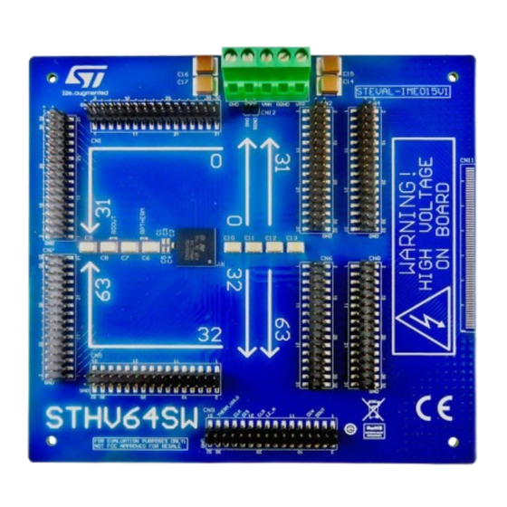
Figure 1.
STEVAL-IME015V1 evaluation board
UM2482 - Rev 1 - December 2018
www.st.com
For further information contact your local STMicroelectronics sales office.
Advertisement
Table of Contents

Related Manuals for ST STEVAL-IME015V1


Summary of Contents for ST STEVAL-IME015V1
- Page 1 UM2482 User manual How to use the evaluation board for the STHV64SW high voltage switch matrix Introduction The STEVAL-IME015V1 evaluation board is based on the STHV64SW high voltage switch matrix, designed for ultrasound imaging applications. The system can switch 64 independent high voltage channels through switch input and output connections on standard 2.54 mm headers, as well as through digital I/O’s.
-
Page 2: Steval-Ime015V1 Evaluation Board Overview
UM2482 STEVAL-IME015V1 evaluation board overview STEVAL-IME015V1 evaluation board overview The STEVAL-IME015V1 evaluation board for the STHV64SW switch matrix device features the following characteristics: • Suitable for ultrasound imaging applications • 64 high voltage channels • Switch input and output header connectors •... -
Page 3: Power Supply
ELEMENT INACTIVE ELEMENT ACTIVE ELEMENT INACTIVE ELEMENT Power supply The STEVAL-IME015V1 board is powered through connector CN10: • VDDP: 3.3V DC • VPP: positive high voltage, 0 to +200V DC • VNN: negative high voltage, 0 to -200V DC •... - Page 4 UM2482 STHV64SW switch block Figure 5. STHV64SW switch block Switch STATE Driving circuit RGND UM2482 - Rev 1 page 4/25...
-
Page 5: How To Use The Board
UM2482 How to use the board How to use the board The start using the STEVAL-IME015V1 evaluation board, you only need to perform the following steps: Step 1. Attach an appropriate power supply. Step 2. Connect the channel headers to your oscilloscope. -
Page 6: Digital Interface
UM2482 Digital interface Digital interface The STEVAL-IME015V1 provides full access to all the functional digital I/Os of the STHV64SW device. The STHV64SW digital interface consists of a serial-input parallel-output 64-bit shift register. Table 2. STHV64SW digital interface signals Signal Name... - Page 7 UM2482 Digital interface Figure 6. STHV64SW timing diagram LE_n Dout Dout Dout DOUT Figure 7. STHV64SW digital interface block diagram Digital interface minimum required signals: • DIN – Data In – 1 for ON-STATE – 0 for OFF-STATE • CLK – Clock Signal –...
- Page 8 UM2482 Digital interface • DIS – Disable (Active HIGH) – It resets the logic, and both Latches and FF. They all go to 0. To be left to GND during operation. UM2482 - Rev 1 page 8/25...
-
Page 9: Operating Conditions
UM2482 Operating conditions Operating conditions Unless otherwise specified, VPP = 100 V, VNN = -100 V, VDDP = 3.3 V, RGND = 0 V, Tamb = 25 °C. Table 4. Operating DC supply voltages Symbol Parameter Min. Typ. Max. Value VDDP Positive supply voltage +2.7... -
Page 10: Connectors
UM2482 Connectors Connectors Power supply connector The STEVAL-IME015V1 is powered through connector CN10. Figure 8. Power supply connector CN10 The suggested power up sequence to minimize the risk of damage to user devices attached to STEVAL- IME015V1 is the following:... -
Page 11: Switch I/O Connectors
UM2482 Switch I/O connectors Table 7. Digital interface pin out PIN Number PIN Number(STHV64SW) DOUT LE_N THERM_UVLO Switch I/O connectors There are 8 STHV64SW switch I/Os 32-pin connectors in standard 2.54 mm headers: 4 input and 4 output. Each connector has 16 STHV64SW signals and 16 ground pins. -
Page 12: Table 8. Switches I/Os Connectors Pin Out
UM2482 Switch I/O connectors Table 8. Switches I/Os connectors pin out PIN Number PIN Number(STHV64SW) Connector PIN Number PIN Number(STHV64SW) Connector IN15 OUT15 IN14 OUT14 IN13 OUT13 IN12 OUT12 IN11 OUT11 IN10 OUT10 OUT9 OUT8 OUT7 OUT6 OUT5 OUT4 OUT3 OUT2 OUT1 OUT0... -
Page 13: Optional Standard Probe Connector
OUT63 Optional standard probe connector STEVAL-IME015V1 evaluation board is designed to allow direct connection with an ultrasound probe through a standard medical HDR TC-ZIF 260-pin connector. The connector is not included on the board, but the footprint is available so users can solder any compatible connector. -
Page 14: Table 9. Standard Probe Connector Pinout
UM2482 Optional standard probe connector Figure 11. Standard probe connector CN11 The following table shows the STHV64SW pinout for CN11, all other pins of the CN11 connector are connected to ground. Table 9. Standard probe connector pinout PIN Number PIN Number(STHV64SW) PIN Number PIN Number(STHV64SW) OUT63... - Page 15 UM2482 Optional standard probe connector PIN Number PIN Number(STHV64SW) PIN Number PIN Number(STHV64SW) OUT26 OUT27 OUT28 OUT29 OUT30 OUT31 UM2482 - Rev 1 page 15/25...
-
Page 16: Schematics
UM2482 Schematics Schematics Figure 12. STEVAL-IME015V1 schematics CN1-CN2 OUT0 OUT0 OUT1 OUT1 OUT2 IN10 OUT2 IN10 OUT3 IN11 OUT3 IN11 OUT4 IN12 OUT4 IN12 OUT5 IN13 OUT5 IN13 OUT6 IN14 OUT6 IN14 OUT7 IN15 OUT7 IN15 OUT8 OUT8 OUT9 Header 16X2... - Page 17 UM2482 Schematics Figure 13. STEVAL-IME015V1 schematics CN3-CN4 IN16 IN16 IN17 IN17 IN18 IN18 IN19 IN19 IN20 IN20 IN21 IN21 IN22 IN22 IN23 IN23 IN16 OUT16 IN24 IN16 OUT16 IN24 IN17 OUT17 IN25 IN17 OUT17 IN25 IN18 OUT18 IN26 IN18 OUT18...
- Page 18 UM2482 Schematics Figure 14. STEVAL-IME015V1 schematics CN5-CN6 IN32 IN32 IN33 IN33 IN34 IN34 IN35 IN35 IN36 IN36 IN37 IN37 IN38 IN38 IN39 IN39 IN32 OUT32 IN40 IN32 OUT32 IN40 IN33 OUT33 IN41 IN33 OUT33 IN41 IN34 OUT34 IN42 IN34 OUT34...
- Page 19 UM2482 Schematics Figure 15. STEVAL-IME015V1 schematics CN7-CN8 IN48 IN48 IN49 IN49 IN50 IN50 IN51 IN51 IN52 IN52 IN53 IN53 IN54 IN54 IN55 IN55 IN48 OUT48 IN56 IN48 OUT48 IN56 IN49 OUT49 IN57 IN49 OUT49 IN57 IN50 OUT50 IN58 IN50 OUT50...
- Page 20 UM2482 Schematics Figure 17. STEVAL-IME015V1 schematics CN11 U_STHV64SW_bank1 U_STHV64SW_bank3 STHV64SW_bank1.SchDoc STHV64SW_bank3.SchDoc IN32 IN33 CN11 IN34 OUT31 IN35 OUT30 IN36 OUT29 IN37 U_STHV64SW_control OUT28 IN38 STHV64SW_control.SchDoc OUT27 IN39 OUT26 DOUT IN40 OUT25 LE_N IN41 OUT24 IN10 IN42 OUT23 IN11 IN43 OUT22...
-
Page 21: Revision History
UM2482 Revision history Table 10. Document revision history Date Version Changes 04-Dec-2018 Initial release. UM2482 - Rev 1 page 21/25... -
Page 22: Table Of Contents
STEVAL-IME015V1 evaluation board overview........ - Page 23 STEVAL-IME015V1 schematics CN9-CN10-CN12 ........
- Page 24 UM2482 List of tables List of tables Table 1. Power related jumpers ..............3 Table 2.
- Page 25 ST’s terms and conditions of sale in place at the time of order acknowledgement. Purchasers are solely responsible for the choice, selection, and use of ST products and ST assumes no liability for application assistance or the design of Purchasers’...
Need help?
Do you have a question about the STEVAL-IME015V1 and is the answer not in the manual?
Questions and answers