Table of Contents
Advertisement
Quick Links
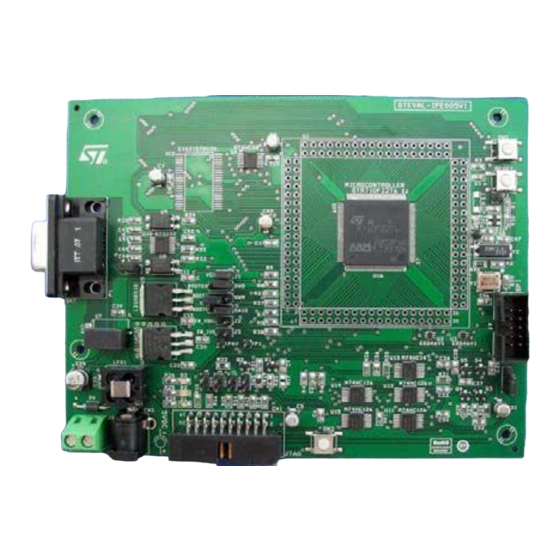
STEVAL-IPE005V1, STPM01 programmer board - hardware
Introduction
The STPM01 - programmer kit works in conjunction with the STPM01 energy meter ASSP
device and with the STPM01 manager software. It is an integrated system designed to
provide the user with a complete, ready-to-use energy meter application. The reference
design is a high-end solution for power metering based on the STR710 microcontroller with
an embedded RTC and an external memory interface (EMI) ready to drive 1Mbyte of on-
board SRAM.
The kit also integrates an on-board optical insulated serial line allowing isolation of the
board ground reference in order to avoid propagation of overvoltage on the PC side.
Moreover, the on-board charge pump allows burning the STPM01 energy meter ASSP
device registers.
Access to the STPM01 device registers is ensured using a dedicated SPI bus interface.
The STPM01 programmer kit demonstrates how effectively the STPM01 can be used in
real-world energy meter applications and it helps the user to develop his own application.
The STPM01 programmer kit can be used in two ways:
■
For demonstration purposes, by connecting the reference design to an AC power source
and changing all the settings parameters through the GUI interface and the hardware
programmer/reader board
■
To evaluate and develop a custom application
March 2008
www.BDTIC.com/ST
Rev 1
UM0509
User manual
1/21
www.st.com
Advertisement
Table of Contents

Related Manuals for ST STEVAL-IPE005V1


Summary of Contents for ST STEVAL-IPE005V1
- Page 1 UM0509 User manual STEVAL-IPE005V1, STPM01 programmer board - hardware Introduction The STPM01 - programmer kit works in conjunction with the STPM01 energy meter ASSP device and with the STPM01 manager software. It is an integrated system designed to provide the user with a complete, ready-to-use energy meter application. The reference...
-
Page 2: Table Of Contents
Revision history ......... . . 20 2/21 www.BDTIC.com/ST... - Page 3 Charge pump and SPI connector ..........19 3/21 www.BDTIC.com/ST...
-
Page 4: Overview
Overview Recommended reading This documentation describes how to configure and use the STPM01 programmer kit hardware. Additional information can be found in the following documents: ● Datasheets of ST devices ● Datasheets of third party devices ● Dedicated application notes ●... -
Page 5: Stpm01 Kit Components
SPI connector A devoted SPI connector allows interfacing the STPM01 device. It provides all the SPI signals required to communicate with the STPM01 interface registers. Moreover it provides a 24 V line which allows burning the STPM01 configuration registers. 5/21 www.BDTIC.com/ST... -
Page 6: Status Leds
STPM01 kit components UM0509 Status LEDs Table 1. Status LEDs Description +5 V power +3.3 V power 1.8 V power Jumper placement Figure 1. STPM01 programmer kit option jumper placement 6/21 www.BDTIC.com/ST... -
Page 7: Jumper Position
BOOT EN: – Fitted (1-2): GND Not fitted – Fitted (2-3): 3.3 V BOOT1: – Fitted (1-2): 3.3 V Not fitted – Fitted (2-3): GND BOOT0: SW10 – Fitted (1-2): 3.3 V Not fitted – Fitted (2-3): GND 7/21 www.BDTIC.com/ST... -
Page 8: Description Of Push-Buttons And Default Value
2.11 Description of connectors Figure 3. STPM01 programmer kit: placement of connectors Table 4. Connectors (refer to Figure Connector Description Opto - isolated RS232 female connector DC-IN 5 V connector DC-IN 5 V connector JTAG connector SPI connector 8/21 www.BDTIC.com/ST... -
Page 9: Boot Configuration
– System executes code from internal RAM 1 (2-3) 1 (1-2) 0 (2-3) RAM mapped at 0h – For lab development – System executes code from EXTMEM mapped at external memory 1 (2-3) 1 (1-2) 1 (1-2) EXTMEM – Not allowed 9/21 www.BDTIC.com/ST... -
Page 10: Connectors
Table 6. RS232 connector pinout P1 Description Shorted to pins 6 and 2 Shorted to pins 1 and 6 TX-0_PC (R1IN) RX-0_PC (T1OUT) Shorted to pins 1 and 2 Shorted to pin 8 Shorted to pin 7 Not connected 10/21 www.BDTIC.com/ST... -
Page 11: Debug
UM0509 Connectors Debug Figure 6. JTAG standard interface: CN1 Table 7. JTAG interface pinout: CN10 Description Even pins Ground VTref+3.3 V Vsupply+3.3 V notTRST RTCK (ground) noTReset DBGRQS - pulled down Pulled down 11/21 www.BDTIC.com/ST... -
Page 12: Stpm01 Programmer Kit Schematics
STPM01 programmer kit schematics UM0509 STPM01 programmer kit schematics Microcontroller and main parts schematic Figure 7. Microcontroller and main parts schematic 12/21 www.BDTIC.com/ST... -
Page 13: Power Management
UM0509 STPM01 programmer kit schematics Power management Figure 8. Power management schematic 13/21 www.BDTIC.com/ST... -
Page 14: Reset And Clock Circuits
STPM01 programmer kit schematics UM0509 Reset and clock circuits Figure 9. Reset and clock circuits 14/21 www.BDTIC.com/ST... -
Page 15: Boot Management And Jtag Circuit
UM0509 STPM01 programmer kit schematics Boot management and Jtag circuit Figure 10. Boot management and Jtag circuits 15/21 www.BDTIC.com/ST... -
Page 16: Figure 11. Opto-Isolated Uart
STPM01 programmer kit schematics UM0509 Figure 11. Opto-isolated UART 16/21 www.BDTIC.com/ST... -
Page 17: External Ram Memory
UM0509 STPM01 programmer kit schematics External RAM memory Figure 12. External RAM memory 17/21 www.BDTIC.com/ST... -
Page 18: Spi Signals Buffering
STPM01 programmer kit schematics UM0509 SPI signals buffering Figure 13. SPI signals buffering 18/21 www.BDTIC.com/ST... -
Page 19: Charge Pump And Spi Connector
UM0509 STPM01 programmer kit schematics Charge pump and SPI connector Figure 14. Charge pump and SPI connector 19/21 www.BDTIC.com/ST... -
Page 20: Revision History
Revision history UM0509 Revision history Table 8. Document revision history Date Revision Changes 14-Mar-2008 Initial release 20/21 www.BDTIC.com/ST... - Page 21 No license, express or implied, by estoppel or otherwise, to any intellectual property rights is granted under this document. If any part of this document refers to any third party products or services it shall not be deemed a license grant by ST for the use of such third party products or services, or any intellectual property contained therein or considered as a warranty covering the use in any manner whatsoever of such third party products or services or any intellectual property contained therein.
Need help?
Do you have a question about the STEVAL-IPE005V1 and is the answer not in the manual?
Questions and answers