Table of Contents
Advertisement
Quick Links
Advertisement
Table of Contents

Related Manuals for Grunbeck violiQ:UV20


Summary of Contents for Grunbeck violiQ:UV20
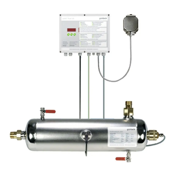
- Page 1 We understand water. UV disinfection system | violiQ:UV20/66/85 Operation manual...
- Page 2 General Contact Germany International Sales Phone +49 9074 41-145 Service Phone 09074 41-333 service@gruenbeck.de Availability Monday to Thursday 7:00 am - 6:00 pm Friday 7:00 am - 4:00 pm We reserve the right to technical modifications. © by Grünbeck Wasseraufbereitung GmbH Original operation manual Edition: March 2022 Order no.: 100155850000_en_014...
-
Page 3: Table Of Contents
Table of contents Table of contents Handing over the product to the owner/operating Introduction ............... 4 company ..............36 Validity of the manual ..........4 Other applicable documents ........4 Operation ..............37 Product identification ..........5 Operating concept ............37 Symbols used ............6 Operating elements and display .......38 Depiction of warnings .......... -
Page 4: Introduction
DIN 19294-1. Grünbeck’s UV-disinfection systems violiQ:UV20/66/85 meet this requirement. For proper operation, the UV disinfection systems violiQ:UV20/66/85 must be installed and operated in accordance with the stipulations of DVGW worksheet W 294-1. -
Page 5: Product Identification
Introduction Product identification You can identify your product based on the product designation and the order no. indicated on the type plate. ► Check whether the products indicated in chapter 1.1 correspond to your product. The type plates are located on the control unit and the irradiation chamber. Designation Designation Obey the operation manual... -
Page 6: Symbols Used
Introduction Symbols used Symbol Meaning Danger and risk Important information or requirement Useful information or tip Written documentation required Reference to further documents Work that must be carried out by qualified specialists only Work that must be carried out by qualified electricians only Work that must be carried out by technical service personnel only Depiction of warnings This manual contains information and instructions that you must obey for your personal... -
Page 7: Demands On Personnel
Introduction Demands on personnel During the individual phases in the service life of the system, different persons carry out work on the system. This work requires different qualifications. 1.6.1 Qualification of personnel Personnel Requirements • No special expertise required Operator/user •... - Page 8 Introduction 1.6.3 Personal protective equipment ► As an owner/operating company, make sure that the required personal protective equipment is available. The components below fall under the heading of personal protective equipment (PPE): Protective gloves Protective footwear Protective overall Safety goggles UV safety goggles Mask 8 | 64...
-
Page 9: Safety
According to § 11 of the German Drinking Water Ordinance, UV disinfection systems must only be used if tested according to DIN 19294-1. Grünbeck’s UV disinfection systems violiQ:UV20/66/85 meet this requirement. ● In Germany, only DVGW-certified UV disinfection systems are approved for use in the drinking water sector. - Page 10 Safety 2.1.2 Pressure-related hazards ● Components can be under pressure. There is a risk of injuries and damage to property due to escaping water and unexpected movement of components. Check the system’s pressure lines for leaks at regular intervals. ● Before starting repair and maintenance work, make sure that all affected components are depressurised.
- Page 11 Safety Mixing and residual amounts of chemicals ● Do not mix different chemicals. Unforeseeable chemical reactions posing a lethal danger can occur. ● Dispose of residual amounts of chemicals in accordance with local regulations and/or in-house instructions. ● Residual amounts from used containers should not be transferred into containers with fresh chemicals in order not to impair the effectiveness of the chemicals.
-
Page 12: Product-Specific Safety Instructions
Safety Product-specific safety instructions 2.2.1 Safety devices CAUTION Operation without safety device ● Without a safety device, the UV disinfection system cannot be operated according to the German Drinking Water Ordinance. ● There is a risk that water which is not or insufficiently disinfected might enter the installation downstream of the UV disinfection system. -
Page 13: Conduct In Emergencies
Safety Conduct in emergencies 2.3.1 In case of water leaks 1. De-energise the system – pull the mains plug. 2. Locate the leak. 3. Eliminate the cause of the water leak. 13 | 64... -
Page 14: Product Description
Product description Product description Intended use ● The UV disinfection systems violiQ:UV are designed for the disinfection of cold drinking water. ● The UV disinfection systems violiQ:UV are to be installed downstream of the water treatment systems. ● The room irradiation required to kill bacteria and viruses is at least 400 J/m². At this room irradiation, a reduction rate of 99.99 % is achieved. -
Page 15: Application Limits
UV systems. ● The service life of the flow stabilisers is 12 months. The flow stabilisers must be replaced during the annual major maintenance (refer to chapter 8.4.2). Application limits violiQ:UV20 violiQ:UV66 violiQ:UV85 5 – 70 Water temperature °C... - Page 16 Product description 3.2.1.2 Operating and suitability characteristic violiQ:UV20 violiQ:UV66 violiQ:UV85 Designation Designation Flow in m³/h Irradiance in W/m² Spectral attenuation coefficient SSK in m 16 | 64...
-
Page 17: Product Components
Product description Product components Designation Function Control unit violiQ:UV To control, monitor and forward signals Ball valve Outlet for flushing the irradiation chamber and for venting Water meter Standard, for water inlet screw connection Irradiation chamber Pressure pipe made of stainless steel as reactor housing Protective quartz pipe To house the UV lamp Sensor shell... -
Page 18: Functional Description
In order to continue to guarantee the required room irradiation, the UV lamp must be replaced at the end of its service life. Subject to being operated properly, all UV disinfection systems violiQ:UV20/66/85 meet the effective minimum room irradiation of 400 J/m² required by the standards. -
Page 19: Accessories/Optional Equipment
522 810 Wall bracket for UV systems 523 800 To mount the UV system on the wall Floor rack To place the UV system on the floor violiQ:UV20 523 815 violiQ:UV66 523 805 violiQ:UV85 523 810 USB data logger for violiQ:UV... -
Page 20: Transport, Set-Up And Storage
Transport, set-up and storage Transport, set-up and storage Shipping/Delivery/Packaging The system is fixed on a pallet at the factory and secured against tipping. ► Upon receipt, immediately check for completeness and transport damage. Transport/Set-up ► Transport the product in its original packaging only. ►... -
Page 21: Installation
Installation Installation The installation of the system must be carried out by a qualified specialist only. The installation site must offer adequate space. The required connections must be provided prior to the installation of the system. Space required and installation dimensions (for wall mounting) 21 | 64... - Page 22 Installation Space required and installation dimensions (with floor rack) Dimensions and weights violiQ:UV20 violiQ:UV66 violiQ:UV85 Installation length with screw connection 1212 Total length with screw connection 1185 1430 Overall height above centre of connection with screw connection Overall height below centre of connection...
-
Page 23: Requirements For The Installation Site
Installation Requirements for the installation site Obey the local installation directives, general guidelines and technical specifications. ● The adequately dimensioned installation surface of the system must be level and provide sufficient strength and load-bearing capacity to support the operating weight of the system. ●... -
Page 24: Checking The Scope Of Supply
Installation Checking the scope of supply ● 1 Stainless steel pressure pipe (irradiation chamber) ● 1 Protective quartz pipe ● 1 Moulded seal for the protective quartz pipe ● 1 Sealing paste for installing the protective quartz pipe ● 1 UV lamp The UV sensors have a special warranty period of a maximum of 4,000 operating hours or 12 months after installation if 4,000 operating hours have not yet been reached by then. - Page 25 Installation NOTE If the protective quartz pipe breaks, water might leak. ● The safety valve installed downstream of the UV system does not prevent water from leaking from the pipe network. ► Make sure that there is a floor drain in the installation room. »...
- Page 26 Installation 5.4.1 Installing the flow stabilisers Pay attention to the mounting direction of the flow stabilisers, otherwise they will be pushed out of the receiving disc. Designation Designation Long union nut Flow stabiliser (1x red) Insert Flow stabiliser (1x red, 2x black) HDPE seal Flow stabiliser (1x red, 2x blue) Connection at the UV system...
-
Page 27: Electrical Installation
Installation Electrical installation The electrical installation must be carried out by a qualified electrician only. DANGER Life-threatening voltage of 230 V on terminals 20 ... 25 ● Severe burns, cardiovascular failure, fatal electric shock ► Check the system for proper condition before start-up/commissioning. ►... - Page 28 Installation The reactor housing of the UV disinfection system must be connected to the building’s equipotential bonding system via a PE cable with a cross-section of 6 mm² – 16 mm². The UV systems are electrically pre-wired. Therefore, only possible signal lines or signal transmitters must be connected to the voltage- free contacts.
- Page 29 Installation 5.5.1 Electrical connections Circuit board Designation Designation Irradiance pre-alarm N.C. Temperature sensor PT100 (optional) max. 24 V~ / max. 1 A Maintenance signal active Collective fault signal active max. 24 V~ / max. 1 A max. 24 V~ / max. 1 A 29 | 64...
- Page 30 Installation Terminal diagram Item Component Terminal Signal Colour of litz wire Mains cable XP1 L 230 V / 50 Hz phase BN/BK (brown or black) Fuses F1 and F2 XP1 N Neutral conductor BU (blue) (2 A T each) internal fuse protection XP1 PE Protective conductor...
-
Page 31: Start-Up/Commissioning
Start-up/commissioning Start-up/commissioning The initial start-up/commissioning of the product must be carried out by technical service personnel only. Installing the protective quartz pipe NOTE Do not touch the protective quartz pipe with bare hands. ● Touching it with bare hands will decrease performance. ►... -
Page 32: Installing The Uv Lamp
Start-up/commissioning In order to facilitate the installation, you can apply some sealing paste to the inside of the seal. This also facilitates removal in case of maintenance. NOTE Do not touch the protective quartz pipe with bare hands. ● Touching it with bare hands will decrease performance. ●... - Page 33 Start-up/commissioning Designation Designation UV lamp Screw-in part Connector of the connection cable Cable gland 1. Insert the UV lamp into the protective quartz pipe up to about 60 mm. 2. Connect the UV lamp with the connector of the connection cable. 3.
-
Page 34: Setting The Control Unit
Start-up/commissioning Setting the control unit For operation and handling of the control unit, refer to chapter 7. The control unit is pre-set at the factory. As a rule, it is not necessary to adjust the control unit. ► Should you detect a deviation during start-up/commissioning: Inform Grünbeck's technical service ►... - Page 35 Start-up/commissioning ● After the system is switched on, the irradiance value displayed slowly starts to rise. » As long as the value remains below the set limit value for the alarm, the red alarm LED lights up and the safety valve remains closed. »...
-
Page 36: Handing Over The Product To The Owner/Operating Company
Start-up/commissioning Handing over the product to the owner/operating company ► Explain to the owner/operating company how the product works. ► Use the manual to brief the owner/operating company and answer any questions. ► Inform the owner/operating company about the need for inspections and maintenance. -
Page 37: Operation
Operation Operation The UV disinfection systems must only be operated if all components are installed properly. Safety equipment must never be removed, bridged or otherwise tampered with or disabled. The UV disinfection systems are operated and monitored by means of the control unit violiQ:UV. -
Page 38: Operating Elements And Display
● The numerical value of the irradiance indicator increases continuously. • The ALARM LED lights up according to the irradiance indicator and the system type (violiQ:UV20/66/85). • The voltage-free contacts ALARM, pre-alarm and service are either open or closed depending on the condition of the ALARM LED and the remaining service interval period. - Page 39 Operation Designation Meaning/Function Operating keys Display Basic display of irradiance XX.XX in W/m² LEDs Indicate current operations by flashing or lighting up Display values Explanation of the key function and corresponding indication in the display 7.2.1 Display of Info level Display Unit days...
- Page 40 Operation 7.2.2 Programming parameters Meaning/Function • Press and hold key > 1 sec: Access to the user programming level (optional temperature- controlled flushing unit) • Opening the parameter for editing (display value starts flashing). • Saving parameter (display value stops flashing) •...
- Page 41 Operation 7.2.3.3 Temperature-controlled flushing unit (optional) Refer to the mounting instructions of the temperature-controlled flushing unit (order no. 523 825). The scope of supply includes a contact temperature sensor and a flushing solenoid valve ½" for installation on the flushing connection. ●...
-
Page 42: Maintenance And Repair
Maintenance and repair Maintenance and repair Maintenance and repair includes cleaning, inspection and maintenance of the product. The responsibility for inspection and maintenance is subject to local and national requirements. The owner/operating company is responsible for compliance with the prescribed maintenance and repair work. As far as the UV disinfection of drinking water is concerned, the measures stipulated in the DIN work sheet W 19294-1 must strictly be adhered to. - Page 43 Maintenance and repair 8.1.1 Flushing the UV system By flushing the UV system, deposits which have settled in the UV system during operation, are removed. These deposits consist for example of iron, manganese, copper, scale, etc. For the flushing, a flushing kit and a cleaning agent are required (refer to chapters 3.5 and 8.5).
-
Page 44: Intervals
Maintenance and repair Intervals By way of regular inspections and maintenance, malfunctions can be detected in time and system failures might be avoided. ► As owner/operating company determine which components must be inspected and maintained at which intervals (load-dependent). The intervals are subject to the actual conditions such as: water condition, degree of impurities, environmental impacts, consumption, etc. -
Page 45: Maintenance
Maintenance and repair Maintenance Regular work is required in order to ensure the proper functioning of the product in the long term. DIN 19294-1 stipulates regular maintenance to ensure trouble-free and hygienic operation of the product. Annual maintenance work requires expert knowledge. The maintenance work must be carried out by technical service personnel only. -
Page 46: Consumables
The operational safety of the system can be impaired if spare parts purchased from other manufacturers are used. Illustration Product Order no. Electronic ballast violiQ:UV20 523 111e 523 121e violiQ:UV66 523 131e violiQ:UV85 Protective quartz pipe with sealing ring... -
Page 47: Wearing Parts
Wearing parts must be replaced by qualified specialists only. The parts listed below are considered to be wearing parts: Illustration Product Order no. Replacement UV lamp The UV lamps (UV-C) have a violiQ:UV20 523 112 service life of up to 16,000 523 122 violiQ:UV66 hours 523 132... -
Page 48: Troubleshooting
Troubleshooting Troubleshooting WARNING Contaminated drinking water due to stagnation ● Infectious diseases ► Have malfunctions eliminated immediately. The UV disinfection systems are equipped with an error detection and reporting system. Malfunctions are indicated on the violiQ:UV control unit by means of the ALARM LED. The messages below can be emitted as voltage-free contacts: ●... -
Page 49: Checking The Uv Lamp
Troubleshooting Display Explanation Remedy ► Check connector plug of UV Er 5 or EEEE displayed Wire break of UV sensor sensor – plugged in correctly? ► Contact technical service ► Temporarily deactivate the Er 6 or Er 7 Wire break or short circuit of the temperature sensor (only if the option temperature-controlled optional temperature flushing unit... - Page 50 Troubleshooting » The UV lamp ignites after a few seconds. 4. Switch off the UV system using the mains switch. 5. If necessary, replace a defective UV lamp by a replacement UV lamp (refer to chapter 8.7). 6. Switch on the UV system after a wait time of 60 s using the mains switch. 7.
- Page 51 Troubleshooting 9.2.2 Mechanical destruction of the lamp and the protective quartz pipe Water contaminated with mercury in the UV system due to defective WARNING protective quartz pipe and defective UV lamp ● Health risk ► Collect the contaminated water in a container and store it in an air-tight manner until the water can be disposed of.
-
Page 52: Decommissioning
Decommissioning Decommissioning It is not necessary to take your product out of operation. In case of longer absences, e.g. holidays, precautionary hygiene measures according to VDI 3810-2 and VDI 6023-2 must be taken in order to maintain drinking water hygiene after downtimes. -
Page 53: Dismantling And Disposal
Dismantling and disposal Dismantling and disposal 11.1 Dismantling The work described herein represents an intervention into your drinking water system. ► Have this work carried out by qualified specialists only. 1. De-energise the system (discharge possible residual voltage). 2. Close the shut-off valves upstream and downstream of the system. 3. - Page 54 Dismantling and disposal ► Contact a suitable waste management company such as a collecting point for problem substances. Never and under no circumstances discharge residues of mercury and its compounds to the sink/floor drain or drain connection – formation of amalgam in the lead siphon and environmental poisoning.
-
Page 55: Technical Specifications
Technical specifications Technical specifications 12.1.1 Installation with wall mounting Dimensions and weights violiQ:UV20 violiQ:UV66 violiQ:UV85 Installation length with screw connection 1212 Total length with screw connection 1185 1430 Overall height above centre of connection with screw connection Overall height below centre of connection... - Page 56 Technical specifications 12.1.2 Installation with floor rack Dimensions and weights violiQ:UV20 violiQ:UV66 violiQ:UV85 Installation length with screw connection 1212 Total length with screw connection 1185 1430 Overall height above centre of connection with screw connection Overall height below centre of connection...
- Page 57 Technical specifications Connection data violiQ:UV20 violiQ:UV66 violiQ:UV85 Nominal connection diameter DN 25 (1") DN 40 (1½") DN 50 (2") ≥ DN 50 Drain connection Installation position horizontal, outlet at the top, self-venting Rated voltage range 230 (15/+10 %) Rated frequency...
-
Page 58: Operation Log
Operation log Operation log ► Document the initial start-up/commissioning and all maintenance activities. ► Copy the maintenance report. UV disinfection system violiQ:UV _________ Serial no.: ______________________________ 13.1 Start-up/commissioning log Customer Name Address Installation/Accessories Drinking water filter (make/type): Drain connection acc. to DIN EN 1717 Floor drain present Safety device Water pipe upstream of... - Page 59 Operation log Maintenance no.: ___ Enter the measured values and operating data. Confirm the checks with OK or record any repairs carried out. Operating values Operating time Max. flow (note down the colour of the flow stabilisers m³/h Irradiance pre-alarm (check on electronics) W/m²...
- Page 60 Operation log Maintenance no.: ___ Enter the measured values and operating data. Confirm the checks with OK or record any repairs carried out. Operating values Operating time Max. flow (note down the colour of the flow stabilisers m³/h Irradiance pre-alarm (check on electronics) W/m²...
- Page 61 Operation log Maintenance no.: ___ Enter the measured values and operating data. Confirm the checks with OK or record any repairs carried out. Operating values Operating time Max. flow (note down the colour of the flow stabilisers m³/h Irradiance pre-alarm (check on electronics) W/m²...
- Page 64 Grünbeck Wasseraufbereitung GmbH Josef-Grünbeck-Str. 1 89420 Hoechstaedt/Germany +49 9074 41-0 +49 9074 41-100 info@gruenbeck.com For more information go to www.gruenbeck.com www.gruenbeck.com...
Need help?
Do you have a question about the violiQ:UV20 and is the answer not in the manual?
Questions and answers