Stahl 8146/5 Operating Instructions Manual
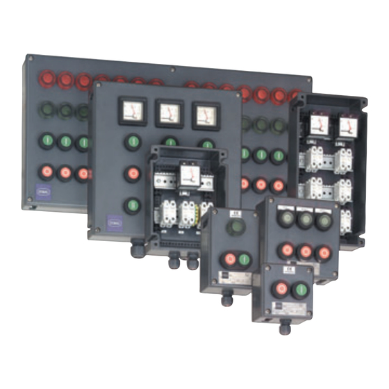
Control paneis and distribution systems
Hide thumbs
Also See for 8146/5:
- Operating instructions manual (45 pages) ,
- Operating instructions manual (36 pages) ,
- Operating instructions manual (41 pages)

Related Manuals for Stahl 8146/5


Summary of Contents for Stahl 8146/5
- Page 1 Betriebsanleitung/Operating Instructions Steuerung und Verteilung Control Panels and Distribution Systems > 8146/5...
- Page 3 Betriebsanleitung Steuerung und Verteilung > 8146/5...
-
Page 4: Table Of Contents
Installation ......................8 Inbetriebnahme ....................14 Wartung .......................15 Zubehör und Ersatzteile ..................18 EG-Baumusterprüfbescheinigung (1. Seite) ............20 EG-Konformitätserklärung ...................21 Allgemeine Angaben 2.1 Hersteller R. STAHL Schaltgeräte GmbH Am Bahnhof 30 74638 Waldenburg, Germany Telefon: +49 7942 943-0 Telefax: +49 7942 943-4333 Internet: www.stahl.de 2.2 Angaben zur Betriebsanleitung... -
Page 5: Allgemeine Sicherheitshinweise
Warnhinweise sind in dieser Betriebsanleitung nach folgendem Schema gegliedert: WARNUNG Art und Quelle der Gefahr! Mögliche Folgen. Maßnahmen zur Vermeidung der Gefahr. Sie sind immer mit dem Signalwort „WARNUNG“ und teilweise mit einem gefahrenspezifischen Symbol gekennzeichnet. 137193 / 8146620300 Steuerung und Verteilung S-BA-8146/5-04-de-16/02/2009 8146/5... -
Page 6: Vorgesehener Einsatzbereich
Die Steuerungen 8146/5 sind zugelassen für den Einsatz in explosionsgefährdeten Bereichen der Zonen 1,2 sowie 21 und 22. Vorgesehener Einsatzbereich Die Steuer- und Verteilerkästen sowie die Schalt- und Verteileranlagen 8146/5 dienen zusammen mit ihren Einbaugeräten zum Steuern, Schalten und Fortleiten elektrischer Energie. -
Page 7: Technische Daten
Klemmentypen und Ex Bauteilen. Anschluss auftragsbedingt direkt auf die Einbaugeräte oder auf Reihenklemmen Schutzart IP66 (abhängig von eingesetzten Einbaugeräten) Umgebungsbedingungen - 20 °C ...+ 40 °C ... (abhängig von eingesetzten Einbaugeräten) 137193 / 8146620300 Steuerung und Verteilung S-BA-8146/5-04-de-16/02/2009 8146/5... - Page 8 8146/...6 Flanschdicke Maß 91 mm 131 mm 150 mm 190 mm 230 mm [mm] [mm] 8146/.03. 8146/.04. 04309E00 8146/.24. 8146/.05. 8146/.06. Additionsmaß bei Flanschmontage 8146/.07. 8146/.S7. 8146/.08. 8146/.09. X ... lieferbare Ausführung Steuerung und Verteilung 137193 / 8146620300 8146/5 S-BA-8146/5-04-de-16/02/2009...
-
Page 9: Transport, Lagerung Und Entsorgung
Montage durch Direktmontage und Montage mit Rahmensystem 8298 möglich.(Mon- tage mit Rahmensystem nur bei den Gehäusen 8146/.7., 8146/.8. und 8146/.9. möglich) Je nach Typ und Anzahl der Einbaugeräte das Gewicht des Gehäuses beachten. 137193 / 8146620300 Steuerung und Verteilung S-BA-8146/5-04-de-16/02/2009 8146/5... -
Page 10: Installation
Installation Zur Vermeidung einer Kondensatbildung innerhalb der Gehäuse empfehlen wir die Verwendung des Klimastutzens Typ 8162 der Fa. R. STAHL Schalt- geräte GmbH. Durch den Einbau des Klimastutzens wird die Schutzart nach IEC 60529 reduziert. Bei beliebiger Einbaulage beträgt die Schutzart IP 64, bei senkrechter Ein- baulage, mit Klimastutzen nach unten, IP 66. - Page 11 500 V AC beträgt und deren Mindestqualität H05 entspricht. Der Durchmesser einzelner Leiter darf nicht weniger als 0,1 mm betragen. Der Durchmesser einzelner Drähte von feindrähtigen Leitern darf nicht we- niger als 0,1 mm betragen. 137193 / 8146620300 Steuerung und Verteilung S-BA-8146/5-04-de-16/02/2009 8146/5...
- Page 12 Original Ex-Zubehör vorgenommen werden. Rüsten Sie die dazu erforderlichen Trennwände bei Bedarf nach. Verwenden Sie bei zusätzlich notwendigem Aufspleißschutz Aderendhülsen oder Kabelschuhe. Der Querschnitt des Aufspleißschutzes muss mit dem Leiterquerschnitt über- einstimmen. Steuerung und Verteilung 137193 / 8146620300 8146/5 S-BA-8146/5-04-de-16/02/2009...
- Page 13 Die zulässige Umgebungstemperatur an den eingebauten eigensicheren Geräten und Komponenten darf nicht überschritten werden. Es muss sicher gestellt werden, dass beim Abisolieren die Leiterisolation bis an die Klemmen heranreicht. Der Leiter darf beim Abisolieren nicht beschädigt werden. 137193 / 8146620300 Steuerung und Verteilung S-BA-8146/5-04-de-16/02/2009 8146/5...
- Page 14 Angaben bezüglich Potentialausgleich (PA), Potentialerde (PE) und eigensi- cheren Stromkreisen entnehmen Sie der Dokumentation der eingebauten Geräte. Schutzleiter für Kabelquerschnitt bis 10 mm 07871E00 Flachkopfschraube (1) abschrauben. PE-Klemmschuh (2) mit Flachkopfschraube (1) fixieren. Steuerung und Verteilung 137193 / 8146620300 8146/5 S-BA-8146/5-04-de-16/02/2009...
- Page 15 Schließen Sie in jedem Fall den Schutzleiter an. Entfernen Sie gegebenenfalls lose Metallteilchen, Verschmutzungen und Feuchtig- keitsspuren aus dem Anschlussgehäuse. Schließen Sie das Gehäuse nach Abschluss der Arbeiten sorgfältig. Führen Sie eine Isolationsprüfung gemäß IEC/EN 60439-1 durch. 137193 / 8146620300 Steuerung und Verteilung S-BA-8146/5-04-de-16/02/2009 8146/5...
-
Page 16: Inbetriebnahme
Wir empfehlen Ihnen für die nicht benutzten Bohrungen im Gehäuse die Ver- schlussstopfen 8290 und für die nicht benutzten Leitungseinführungen die Stopfen des Typs 8161 der Fa. R. STAHL Schaltgeräte GmbH. Steuerung und Verteilung 137193 / 8146620300... -
Page 17: Wartung
Im Rahmen der Wartung prüfen: Leitungen auf festen Sitz. Gerät auf sichtbare Schäden. Einhaltung der zulässigen Temperaturen gem. IEC/EN 60079-0. Bestimmungsgemäße Funktion. 10.2 Reinigung Reinigung mit einem Tuch, Besen, Staubsauger o.Ä. 137193 / 8146620300 Steuerung und Verteilung S-BA-8146/5-04-de-16/02/2009 8146/5... - Page 18 Schutzeinrichtung spricht in zulässigen Grenzwerten an 10 die automatische elektrische Schutzeinrichtung ist richtig eingestellt, automatische Rückstellung nicht möglich 11 spezielle Betriebsbedingungen (falls zutreffend) sind eingehalten 12 Kabel und Leitungen, die nicht benutzt werden, sind richtig abgeschlossen Steuerung und Verteilung 137193 / 8146620300 8146/5 S-BA-8146/5-04-de-16/02/2009...
- Page 19 Betriebsbedingungen (falls zutreffend) sind eingehalten Kabel und/oder Leitungen, die nicht benutzt werden, sind richtig abgeschlossen Umgebungseinflüsse Betriebsmittel sind ausreichend gegen Korrosion, Wetter, Schwingung und andere Störfaktoren geschützt keine übermäßige Staub- oder Schmutzansammlung 137193 / 8146620300 Steuerung und Verteilung S-BA-8146/5-04-de-16/02/2009 8146/5...
-
Page 20: Zubehör Und Ersatzteile
Zubehör und Ersatzteile 11 Zubehör und Ersatzteile WARNUNG Verwendung unzulässiger Zubehör- und Ersatzteile! Herstellerhaftung und Gewährleistung erlischt. Nur Original-Zubehör sowie Original-Ersatzteile der Fa. R. STAHL verwenden. Benennung Abbildung Beschreibung Bestellnummer Gewicht Flansche Größe 2,8 mm dick 135978 0.065 05742E00 Größe... - Page 21 8146/.S73 C / D 136979 0.310 8146/.083 C / D 8146/.093 A / B 8146/.091 /.092 C2 / D2 136957 0.160 8146/.093 C2 / D2 136982 0.310 für Flanschgehäuse 8146 136954 0.120 137193 / 8146620300 Steuerung und Verteilung S-BA-8146/5-04-de-16/02/2009 8146/5...
-
Page 22: Eg-Baumusterprüfbescheinigung (1. Seite)
EG-Baumusterprüfbescheinigung (1. Seite) 12 EG-Baumusterprüfbescheinigung (1. Seite) Steuerung und Verteilung 137193 / 8146620300 8146/5 S-BA-8146/5-04-de-16/02/2009... -
Page 23: Eg-Konformitätserklärung
EG-Konformitätserklärung 13 EG-Konformitätserklärung 137193 / 8146620300 Steuerung und Verteilung S-BA-8146/5-04-de-16/02/2009 8146/5... - Page 25 Operating Instructions Control Panels and Distribution Systems > 8146/5...
- Page 26 Maintenance ......................15 Accessories and spare parts ................18 CE Prototype test certificate (Page 1) ..............20 EC-Declaration of Conformity ................21 General Information 2.1 Manufacturer R. STAHL Schaltgeräte GmbH Am Bahnhof 30 74638 Waldenburg, Germany Phone: +49 7942 943-0 Fax: +49 7942 943-4333 Internet: www.stahl.de...
-
Page 27: General Information
Type and source of the danger! Possible consequences. Measures to avoid danger. They are always identified by the signalling word “WARNING“ and sometimes also have a symbol which is specific to the danger involved. 137193 / 8146620300 Control Panels and Distribution Systems S-BA-8146/5-04-en-16/09/2009 8146/5... -
Page 28: Designated Use
IEC/EN 60079-0, IEC/EN 60079-1, IEC/EN 60079-7, IEC/EN 60079-11, IEC/EN 60079-18 IEC/EN 61241-0, IEC/EN 61241-1 The control panels 8146/5 are certified for use in areas subject to explosion hazards of zones 1, 2, 21 and 22. Designated Use The control and distribution boxes as well as the switch and distribution systems 8146/5, combined with their fitted components, are used to control, switch and transmit electrical energy. -
Page 29: Technical Data
Depending on the order, directly to fitted components or via terminal blocks Ingress Protection IP 66 (depending on the installed equipment) Ambient conditions - 20 °C ... + 40 °C (depending on the installed equipment) 137193 / 8146620300 Control Panels and Distribution Systems S-BA-8146/5-04-en-16/09/2009 8146/5... - Page 30 150 mm 190 mm 230 mm thickness ure a [mm] [mm] 8146/.03. 8146/.04. 04309E00 8146/.24. 8146/.05. Additional dimensions for 8146/.06. flange mounting 8146/.07. 8146/.S7. 8146/.08. 8146/.09. X ... can be supplied Control Panels and Distribution Systems 137193 / 8146620300 8146/5 S-BA-8146/5-04-en-16/09/2009...
-
Page 31: Transport, Storage And Disposal
To prevent condensation in the enclosure, we recommend using a type 8162 breather from R. STAHL Schaltgeräte GmbH. The installation of the breather reduces the type of protection as per IEC 60529. If installed vertically, breather at the bottom, the type of protection is IP66, otherwise IP 64. -
Page 32: Installation
The enclosures must only be opened during installation works and be closed correctly after completing the work. Control Panels and Distribution Systems 137193 / 8146620300 8146/5 S-BA-8146/5-04-en-16/09/2009... - Page 33 Mounting rails or elements must be fastened properly. Loosen the mounting rails or elements for connecting the cables correctly. Make sure that there is sufficient short-circuit current on the mains connection for trip- ping the fuse. 137193 / 8146620300 Control Panels and Distribution Systems S-BA-8146/5-04-en-16/09/2009 8146/5...
- Page 34 1500 V (double the sum of the rated operational voltage of intrinsically-safe circuits plus 1000 V). The conductors of intrinsically safe or non-intrinsically safe circuits are protec- ted by an earthed shield. Control Panels and Distribution Systems 137193 / 8146620300 8146/5 S-BA-8146/5-04-en-16/09/2009...
- Page 35 When stripping insulation, it must be ensured that the conductor insulation reaches right up to the terminals. The conductor itself must not be damaged when removing the insulation. 137193 / 8146620300 Control Panels and Distribution Systems S-BA-8146/5-04-en-16/09/2009 8146/5...
- Page 36 Protective earth conductor for cable cross sections up to 10 mm 07871E00 Unscrew the cheese-head screw (1). Fasten the PE cable lug (2) by means of cheese-head screws (1). Protective earth conductor for cable cross sections up to 70 mm Control Panels and Distribution Systems 137193 / 8146620300 8146/5 S-BA-8146/5-04-en-16/09/2009...
- Page 37 Remove loose metal particles, dirt and traces of moisture from the terminal compart- ment, if any. Carefully close the enclosure after finishing the work. Test the insulation in accordance with IEC/EN 60439-1. 137193 / 8146620300 Control Panels and Distribution Systems S-BA-8146/5-04-en-16/09/2009 8146/5...
-
Page 38: Commissioning
Check whether all covers and barriers for live parts are installed and fixed. We recommend the use of type 8290 stopping plugs for unused holes and type 8161 plugs for unused cable entries in the enclosure. Both are available from R. STAHL Schaltgeräte GmbH. Control Panels and Distribution Systems 137193 / 8146620300... -
Page 39: Maintenance
Compliance with the permitted temperatures in accordance with IEC/EN 60079-0. Make sure that the device is used according to its designated use 10.2 Cleaning Clean with a cloth, brush, vacuum cleaner or similar items. 137193 / 8146620300 Control Panels and Distribution Systems S-BA-8146/5-04-en-16/09/2009 8146/5... - Page 40 11 Special operating conditions (if applicable) are observed 12 Cables not in use are correctly terminated 13 Obstructions adjacent to flameproof joints are in accordance with IEC 60079-14 14 Variable voltage/frequency installation in accordance with documentation Control Panels and Distribution Systems 137193 / 8146620300 8146/5 S-BA-8146/5-04-en-16/09/2009...
- Page 41 Special operating conditions (if applicable) are observed Cables not in use are correctly terminated Ambient conditions Equipment is adequately protected against corrosion, weather, vibration and other ad- verse factors No undue accumulation of dust and dirt 137193 / 8146620300 Control Panels and Distribution Systems S-BA-8146/5-04-en-16/09/2009 8146/5...
-
Page 42: Accessories And Spare Parts
Accessories and spare parts 11 Accessories and spare parts WARNING Use of non-approved accessories and spare parts. The manufacturer’s liability and warranty expire. Use only original accessories and original spare parts manufactured by R. STAHL. Designation Illustration Description Order number... - Page 43 C / D 136979 0.310 8146/.083 C / D 8146/.093 A / B 8146/.091 /.092 C2 / D2 136957 0.160 8146/.093 C2 / D2 136982 0.310 for flange enclosure 8146 136954 0.120 137193 / 8146620300 Control Panels and Distribution Systems S-BA-8146/5-04-en-16/09/2009 8146/5...
- Page 44 EC Prototype test certificate (Page 1) 12 EC Prototype test certificate (Page 1) Control Panels and Distribution Systems 137193 / 8146620300 8146/5 S-BA-8146/5-04-en-16/09/2009...
-
Page 45: Ec-Declaration Of Conformity
EC-Declaration of Conformity 13 EC-Declaration of Conformity 137193 / 8146620300 Control Panels and Distribution Systems S-BA-8146/5-04-en-16/09/2009 8146/5... - Page 48 137193 / 8146620300 S-BA-8146/5-04-de/en-16/02/2009...
Need help?
Do you have a question about the 8146/5 and is the answer not in the manual?
Questions and answers