Advertisement
Quick Links
1
Unpacking
Open the carton and unpack the items. Your package
should include:
▪
One EX33000 Switch
▪
DIN rail mounting kit
If any items are missing or damaged, notify your
EtherWAN representative. If possible, save the carton
and packing material in case you need to ship or store
the switch in the future.
2
Equipment Needed
▪
Category 5 or better cable for RJ-45 ports
▪
Appropriate fiber cable for fiber ports
3
Select a Location
▪
Installation: DIN rail. Place the device on the DIN
rail from above using the slot. Push the front of
the device toward the mounting surface until it
audibly snaps into place.
▪
Choose a dry area with ambient temperature
between -10°C to +60°C (14°F to 140°F).
▪
Keep away from heat sources, sunlight, warm air
exhausts, hot-air vents, and heaters.
▪
Be sure there is adequate airflow.
4
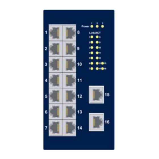
Connect to the Data Ports
Depending on the model, your switch can have the
following ports:
▪
16 10/100Base-TX Ports
▪
15 100Base-FX Port + 1 100BASE-FX port
▪
14 100Base-FX Port + 2 100BASE-FX ports
W70G-NX33000Q2
Page 1
EX33000 Series | Industrial Unmanaged Switch
5
Connect Power
The switch has two pairs of power inputs:
▪
A 12-48VDC terminal block
▪
A 12VDC jack
Only one power input is required to operate the
switch. However, redundant power supply
functionality is supported.
Terminal Block
The switch provides two power inputs on a 12-48VDC
terminal block. The terminal block has 5 terminal
posts.
Pin
+
Power 2
−
+
Power 1
−
Relay Output
Rating
Copyright 2023 EtherWAN Systems, Inc. All Rights Reserved 02/02/2023
Description
12-48VDC
Power Ground
12-48VDC
Power Ground
Earth Ground
1A @ 24VDC
Installation Guide
DC Jack
Pin
Description
Power 3
12VDC
Power Failure Alarm
A 2-pin terminal block is provided for power failure
detection. Do not connect a power source to these
pins.
The relay contact closes if:
▪
Power 1 and Power 2 are both failed, but Power 3
is ON.
▪
Power 3 is failed, but Power 1 and Power 2 are
both ON.
Power-Up Sequence
When the switch is powered up:
▪
All Link/ACT LEDs blink momentarily.
▪
The Power LED lights up and stays lit.
▪
LEDs for every port connected to a device will
flash, as the switch conducts a brief Power On Self-
Test (POST).
Advertisement

Related Manuals for EtherWAN EX33000 Series


Summary of Contents for EtherWAN EX33000 Series
- Page 1 Power On Self- ▪ Test (POST). 15 100Base-FX Port + 1 100BASE-FX port ▪ 14 100Base-FX Port + 2 100BASE-FX ports Copyright 2023 EtherWAN Systems, Inc. All Rights Reserved 02/02/2023 W70G-NX33000Q2 Page 1...
- Page 2 Flashing Transmitting or receiving data EtherWAN Systems, Inc. 33F, No. 93, Sec. 1, Xintai 5th Rd., Xizhi Dist., New Taipei City, 221 Taiwan The full product manual can be downloaded from: www.etherwan.com Copyright 2023 EtherWAN Systems, Inc. All Rights Reserved 02/02/2023 W70G-NX33000Q2 Page 2...
Need help?
Do you have a question about the EX33000 Series and is the answer not in the manual?
Questions and answers