
Related Manuals for Emerson Rosemount 3152


Summary of Contents for Emerson Rosemount 3152
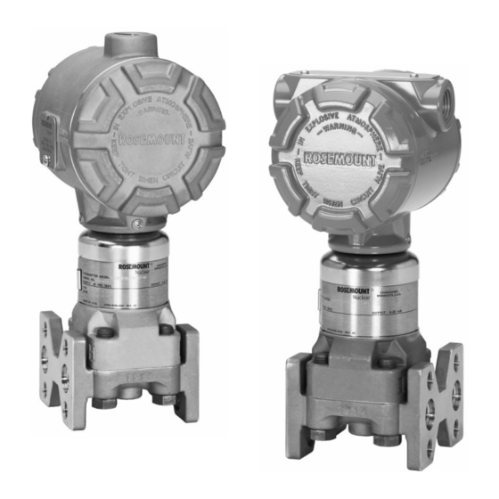
- Page 1 Reference Manual 00809-0100-4835 Rev BE Rosemount 3150 Series February 2018 Rosemount 3150 Series Nuclear Pressure Transmitters Including the Rosemount 3152, 3153, and 3154...
- Page 2 Reference Manual 00809-0100-4835 Rev BE Rosemount 3150 Series February 2018 This page intentionally left blank...
- Page 3 00809-0100-4835 Rev BE Rosemount 3150 Series February 2018 Rosemount 3150 Series Nuclear Pressure Transmitters Including the Rosemount 3152, 3153 and 3154 NOTICE Read this manual before working with the product. For personal and system safety, and for optimum performance, make sure you thoroughly understand the contents of this manual before installing, using or maintaining this product.
- Page 4 Rosemount Nuclear Instruments, Inc. 8200 Market Boulevard Chanhassen, MN 55317 IMPORTANT Rosemount 3152, 3153 and 3154 Series Pressure Transmitters are designed for Nuclear Class 1E usage, and have been tested to the standards shown below: • • IEEE Std 323...
- Page 5 Reference Manual 00809-0100-4835 Rev BE Rosemount 3150 Series February 2018 Revision Status Changes from July 2016 (Rev BD) to February 2018 (Rev BE) Page Page Changes (Rev BD) (Rev BE) Document revision change from July 2016 to February 2018, Rev BD to Rev BE; Updated document formatting, page numbers, spelling, grammar, and references for Cover, Cover,...
- Page 6 Reference Manual 00809-0100-4835 Rev BE Rosemount 3150 Series February 2018 This page intentionally left blank Title Page...
-
Page 7: Table Of Contents
Reference Manual 00809-0100-4835 Rev BE Rosemount 3150 Series February 2018 Table of Contents SECTION 1 Using this Manual..................Introduction SECTION 2 Overview....................Installation Safety Messages..................General Considerations................Mechanical Considerations............... Process Connections and Interfaces........... Impulse Piping................Mounting Configurations.............. Conduit Connections..............Electronics Housing..............Electrical Considerations................ - Page 8 Reference Manual 00809-0100-4835 Rev BE Rosemount 3150 Series February 2018 SECTION 4 Overview....................Operation Transmitter Theory of Operation............... The Sensor Cell..................Demodulator..................... Oscillator....................Voltage Regulator..................Current Control..................Current Limit..................... Reverse Polarity Protection..............SECTION 5 Overview....................Maintenance and Safety Messages..................Troubleshooting General Considerations................
- Page 9 Reference Manual 00809-0100-4835 Rev BE Rosemount 3150 Series February 2018 This page intentionally left blank Contents...
-
Page 10: Using This Manual
Reference Manual 00809-0100-4835 Rev BE Rosemount 3150 Series February 2018 SECTION 1: Introduction This manual is designed to assist in installing, operating and USING THIS MANUAL maintaining the Rosemount 3150 Series Pressure Transmitters. Instructions for the 3152, 3153 and 3154 models are included in this manual. - Page 11 Reference Manual 00809-0100-4835 Rev BE Rosemount 3150 Series February 2018 This page intentionally left blank Introduction...
-
Page 12: Overview
Reference Manual 00809-0100-4835 Rev BE Rosemount 3150 Series February 2018 SECTION 2: Installation Overview..............page 3 Safety Messages............ page 3 General Considerations......... page 4 Mechanical Considerations........page 4 Electrical Considerations........page 10 Installation Procedures.......... page 14 OVERVIEW This section contains the following installation considerations: •... -
Page 13: General Considerations
Reference Manual 00809-0100-4835 Rev BE Rosemount 3150 Series February 2018 WARNING Electrical shock can result in death or serious injury. • Avoid contact with the leads and terminals. Process leaks could result in death or serious injury. • Install and tighten all four flange bolts before applying pressure. -
Page 14: Process Connections And Interfaces
Reference Manual 00809-0100-4835 Rev BE Rosemount 3150 Series February 2018 Mount the Rosemount 3150 Series transmitter to a rigid support (i.e. one with a fundamental mechanical resonant frequency of 40 Hz or greater). Two mounting options are qualified for the transmitter: panel mount or 2-inch pipe mount. A stainless steel panel bracket is provided with the 3154. - Page 15 Reference Manual 00809-0100-4835 Rev BE Rosemount 3150 Series February 2018 ® Figure 2-1 – Swagelok Compression Fitting Detail Dimensions are nominal in inches (mm) Assembly ® The Swagelok tube fittings come completely assembled and are ready for immediate use. Do not disassemble them before use because dirt or foreign materials may get into the fitting ®...
-
Page 16: Impulse Piping
Reference Manual 00809-0100-4835 Rev BE Rosemount 3150 Series February 2018 The piping between the process and the transmitter must Impulse Piping accurately transfer the pressure to obtain accurate measurements. There are five possible sources of error: pressure transfer (such as obstruction), leaks, friction loss (particularly if purging is used), trapped gas in a liquid line or liquid in a gas line and density variations between the legs. - Page 17 Reference Manual 00809-0100-4835 Rev BE Rosemount 3150 Series February 2018 Refer to Figure 2-2 for examples of the following mounting Mounting Configuration configurations: Liquid Flow Measurement • Place taps to the side of the line to prevent sediment deposits on the process isolators. •...
-
Page 18: Conduit Connections
Reference Manual 00809-0100-4835 Rev BE Rosemount 3150 Series February 2018 Figure 2-2 – Transmitter Installation Examples (liquid, gas or steam) Please note that transmitters depicted in Figure 2-2 are intended for reference only. The conduit connections to the transmitter are threaded. Conduit Connections Options available are 1/2-14 NPT, M20 x 1.5, PG 13.5 and G1/2. -
Page 19: Electronics Housing
Reference Manual 00809-0100-4835 Rev BE Rosemount 3150 Series February 2018 The standard transmitter orientation is shown in dimensional Electronics Housing drawings found in this manual (see Figure 2-6). While rotation of the electronics housing in the field is possible with special instructions, it is not recommended. - Page 20 Reference Manual 00809-0100-4835 Rev BE Rosemount 3150 Series February 2018 Figure 2-4 – Transmitter Supply Voltage vs. Load Figure 2-4a – IEEE Qualified and Design Regions (applicable to 3152N, 3153N and 3154N models only) 2500 DESIGN REGION 2150 IEEE 2000 QUALIFIED REGION 1725...
- Page 21 Reference Manual 00809-0100-4835 Rev BE Rosemount 3150 Series February 2018 Figure 2-4b – KTA Qualified and Design Regions (applicable to 3152K and 3154K models only) 2500 DESIGN REGION 2150 2000 1900 QUALIFIED 1500 REGION 1000 POWER SUPPLY (VDC) Figure 2-4c – RCC-E Qualified and Design Regions (applicable to 3153K and 3154K models only) 2500...
-
Page 22: Signal Integrity
Reference Manual 00809-0100-4835 Rev BE Rosemount 3150 Series February 2018 Signal wiring need not be shielded, but twisted pairs yield the Signal Integrity best results. Shielded cable should be used for best results in electrically noisy environments. Do not run signal wiring in conduit or open trays with AC power wiring, or near heavy electrical equipment. -
Page 23: Wiring Connections
Reference Manual 00809-0100-4835 Rev BE Rosemount 3150 Series February 2018 The transmitter terminal block and ground screw terminals are Wiring Connections designed to accommodate wire sizes from 24 AWG to 14 AWG. The screw terminals are also compatible with stud size #6 (M3.5) or #8 (M4) crimp terminals. - Page 24 Reference Manual 00809-0100-4835 Rev BE Rosemount 3150 Series February 2018 Table 2-1 – Recommended Bolts for Bracket-to-Customer Interface Recommended Bolt for Bracket Code Bracket Type Bracket-to-Customer Interface No Bracket Supplied Carbon Steel Panel Bracket 5/16-18 UNC 2A Grade 2 SST Panel Bracket 3/8-24 UNF 2A Grade 2 SST 2-inch Pipe Mount Bracket 2-inch pipe U-bolts provided...
- Page 25 Reference Manual 00809-0100-4835 Rev BE Rosemount 3150 Series February 2018 Figure 2-5 – Typical Transmitter Mounting Bracket Configuration, Traditional Flange (1) (2) Carbon Steel Stainless Steel Stainless Steel Panel Mount Panel Mount 2-Inch Pipe Mount Bracket Options 3152 & 3153 Carbon Steel Panel Mount Bracket is 3154 not available for the 3154...
- Page 26 Reference Manual 00809-0100-4835 Rev BE Rosemount 3150 Series February 2018 Figure 2-6 – Transmitter Dimensional Drawings Figure 2-6a – 3152, 3153 Traditional Flange NOTE: All dimensions are nominal in inches (millimeters) Figure 2-6b – 3154 Traditional Flange NOTE: All dimensions are nominal in inches (millimeters) Installation...
-
Page 27: Mechanical - Conduit
Reference Manual 00809-0100-4835 Rev BE Rosemount 3150 Series February 2018 Mechanical – Conduit CAUTION Be careful not to damage the set screw interface between the Connections sensor module and the electronics housing when making conduit connections. NOTE Install the conduit seal in accordance with the manufacturer’s instructions or use the following procedure: 1. - Page 28 Reference Manual 00809-0100-4835 Rev BE Rosemount 3150 Series February 2018 5. Tighten until cover and housing are fully engaged metal-to-metal (see Figure 2-9). Once metal-to-metal contact has been made, it is not necessary to tighten the cover any further. 6. Visually inspect both covers to ensure they are installed metal-to-metal.
- Page 29 Reference Manual 00809-0100-4835 Rev BE Rosemount 3150 Series February 2018 Figure 2-8 – Internal Ground Screw Location Figure 2-9 – Electronics Housing Covers Installed Metal-to-Metal Aluminum Housing (3152, 3153) SST Housing (3152) SST Housing (3154) Cover / Housing Interface Note Stainless Steel (SST) interface includes chamfers on cover and housing Figure 2-10 –...
- Page 30 Reference Manual 00809-0100-4835 Rev BE Rosemount 3150 Series February 2018 Figure 2-11 – Acceptable vs. Unacceptable Gap Between Cover and Housing Figure 2-11a – Acceptable Gap Between Cover and Housing Aluminum Housing (3152, 3153) SST Housing (3152) SST Housing (3154) Figure 2-11b –...
- Page 31 Reference Manual 00809-0100-4835 Rev BE Rosemount 3150 Series February 2018 This page intentionally left blank Installation...
-
Page 32: Overview
Reference Manual 00809-0100-4835 Rev BE Rosemount 3150 Series February 2018 SECTION 3: Calibration Overview..............page 23 Safety Messages............ page 23 Calibration Overview..........page 24 Calibration Procedures.......... page 28 This section contains the following transmitter calibration OVERVIEW information: • Calibration Overview →... - Page 33 Reference Manual 00809-0100-4835 Rev BE Rosemount 3150 Series February 2018 WARNING Process leaks could result in death or serious injury. • Install and tighten all four flange bolts before applying pressure. • Do not attempt to loosen or remove flange bolts while the transmitter is in service.
- Page 34 Reference Manual 00809-0100-4835 Rev BE Rosemount 3150 Series February 2018 For large amounts of zero adjustment, a coarse zero select jumper is provided. The jumper is located on the electronics assembly, accessible within the electronics housing as shown in Figures 3-1 and 3-2. Models ordered with optional output damping will have a damping adjustment potentiometer located on the amplifier board (see Figure 3-2).
- Page 35 Reference Manual 00809-0100-4835 Rev BE Rosemount 3150 Series February 2018 % Zero Offset = (LRV/URL) X 100 Note: % Zero Offset is used when making coarse zero adjustments and replaces the traditional % Zero Elevation and % Zero Suppression terms. This concept is used due to the limited interaction between zero and span adjustments on the 3150 Series pressure transmitter.
- Page 36 Reference Manual 00809-0100-4835 Rev BE Rosemount 3150 Series February 2018 For transmitter ranges 2 to 6, the span is continuously Span Adjustment Range adjustable to allow calibration anywhere between the transmitter URL and 1/10 of URL. For example, the span on a Range 2 transmitter can be continuously adjusted between 25 and 250 inH O (6,22 kPa and 62,2 kPa).
-
Page 37: Calibration Procedures
Reference Manual 00809-0100-4835 Rev BE Rosemount 3150 Series February 2018 The following calibration procedures describe the CALIBRATION recommended steps necessary to calibrate the Rosemount PROCEDURES 3150 Series pressure transmitters. Span and Zero Adjustment CAUTION The 3150 Series pressure transmitters contain electronic circuit boards which may be static sensitive. -
Page 38: Elevated Or Suppressed Zero Calibration Procedure
Reference Manual 00809-0100-4835 Rev BE Rosemount 3150 Series February 2018 Figure 3-4b – Example for Zero Based Range 2 for a calibration of 0 to 24,9 kPa (24,9 kPa span) Calibration (SI Units) 1. Adjust the zero: With 0 kPa applied to the transmitter, turn the Zero adjustment until the transmitter reads 4 2. - Page 39 Reference Manual 00809-0100-4835 Rev BE Rosemount 3150 Series February 2018 Figure 3-5 – Elevated Zero Calibration Example Figure 3-5a – Example for Elevated Zero Range 2 with Zero Elevation for a calibration of Calibration (English Units) –120 to –20 inH O (100 inH O span) 1.
- Page 40 Reference Manual 00809-0100-4835 Rev BE Rosemount 3150 Series February 2018 Figure 3-5b – Example for Elevated Zero Range 2 with Zero Elevation for a calibration of Calibration (SI Units) –29,9 to –5,0 kPa (24,9 kPa span) 1. Calibrate the transmitter to 0 to 24,9 kPa as described in the Zero Based Calibration Procedure.
- Page 41 Reference Manual 00809-0100-4835 Rev BE Rosemount 3150 Series February 2018 Figure 3-6 – Suppressed Zero Calibration Example Figure 3-6a – Example for Suppressed Zero Range 2 with Zero Suppression for a calibration of Calibration (English Units) 20 to 120 inH O (100 inH O span) 1.
- Page 42 Reference Manual 00809-0100-4835 Rev BE Rosemount 3150 Series February 2018 Coarse Zero Select Jumper The coarse zero select jumper (see Figure 3-2) is shipped Position Selection Procedure from the factory in either the Nominal position or the position required to obtain the calibration specified when ordered. Changes to the factory calibration may require repositioning of the jumper.
- Page 43 Reference Manual 00809-0100-4835 Rev BE Rosemount 3150 Series February 2018 Figure 3-7 contains an example of determining the typical position of the coarse zero select jumper. Figure 3-7a uses English Units (inH O) while Figure 3-7b uses SI Units (kPa). Figure 3-7 –...
-
Page 44: Damping Adjustment
Reference Manual 00809-0100-4835 Rev BE Rosemount 3150 Series February 2018 Figure 3-8b – Ranges 2-6 Jumper Position (Typical) % Zero Offset values and jumper positions indicated are approximations. Select jumper position as needed to achieve the desired calibration. The 3150 Series amplifier boards for transmitter output code Damping Adjustment options B (3152) and T (3153 and 3154) are designed to permit damping of rapid pulsations in the pressure source... -
Page 45: Correction For High Static Line Pressure
Reference Manual 00809-0100-4835 Rev BE Rosemount 3150 Series February 2018 Correction for High Static Line Pressure High Static Line Pressure Span Rosemount 3150 Series Range 1, 2, and 3 differential Effect on Range Codes 1, 2, and 3 pressure transmitters do not require correction for high static DP Transmitters pressure span effect. - Page 46 Reference Manual 00809-0100-4835 Rev BE Rosemount 3150 Series February 2018 NOTE For corrections where the calculated output adjustment exceeds the output high or low adjustment limits, the pressure input adjust procedure described in Method 2 (see pg. 38) is recommended. Figure 3-9 outlines examples of calculating a High Static Line Pressure Span Correction using Method 1.
- Page 47 Reference Manual 00809-0100-4835 Rev BE Rosemount 3150 Series February 2018 Figure 3-9b – Example for High Static Line Range 4 for a calibration of –0,07 to 0,31 MPa corrected Pressure Span Correction using Method 1 for 10,34 MPa static line pressure: (SI Units) 1.
- Page 48 Reference Manual 00809-0100-4835 Rev BE Rosemount 3150 Series February 2018 Figures 3-10 and 3-11 outline two examples of calculating a High Static Line Pressure Span Correction using Method 2. “Example 1” in Figure 3-10 contains a calculation for a Zero Based Calibration Range.
- Page 49 Reference Manual 00809-0100-4835 Rev BE Rosemount 3150 Series February 2018 Figure 3-10b – Example 1 for High Static Line Range 4 for a calibration of 0 to 0,31 MPa corrected for Pressure Span Correction using Method 2 10,34 MPa static line pressure (SI Units) 1.
- Page 50 Reference Manual 00809-0100-4835 Rev BE Rosemount 3150 Series February 2018 Figure 3-11 – High Static Line Pressure Span Correction using Method 2; Example 2 Figure 3-11a – Example 2 for High Static Line Range 5 for a calibration of –250 to 750 psi corrected for Pressure Span Correction using Method 2 1,500 psi static line pressure (English Units)
- Page 51 Reference Manual 00809-0100-4835 Rev BE Rosemount 3150 Series February 2018 Figure 3-11b – Example 2 for High Static Line Range 5 for a calibration of –1,72 to 5,17 MPa corrected Pressure Span Correction using Method 2 for 10,34 MPa static line pressure (SI Units) 1.
-
Page 52: Code 4 And 5 Dp Transmitters
Reference Manual 00809-0100-4835 Rev BE Rosemount 3150 Series February 2018 d. Apply the intended line pressure to high and low sides (zero differential pressure). e. Record the output reading. Subtract the reading in step e from the reading in step c. Note the sign associated with the calculated value, as the sign is maintained for the adjustment in step i. - Page 53 Reference Manual 00809-0100-4835 Rev BE Rosemount 3150 Series February 2018 This page intentionally left blank Calibration...
-
Page 54: Overview
Reference Manual 00809-0100-4835 Rev BE Rosemount 3150 Series February 2018 SECTION 4: Operation Overview..............page 45 Transmitter Theory of Operation......page 46 The Sensor Cell............page 47 Demodulator............page 48 Oscillator..............page 48 Voltage Regulator........... page 48 Current Control............page 49 Current Limit............ -
Page 55: Transmitter Theory Of Operation
Reference Manual 00809-0100-4835 Rev BE Rosemount 3150 Series February 2018 The block diagram in Figure 4-1 illustrates the operation of TRANSMITTER THEORY OF the 3150 Series pressure transmitter. OPERATION The 3150 Series pressure transmitters have a variable capacitance sensor (see Figure 4-2). Differential capacitance between the sensing diaphragm and the capacitor plates is converted electronically to a 2-wire, 4-20 mA dc signal based ����... -
Page 56: Operation
Reference Manual 00809-0100-4835 Rev BE Rosemount 3150 Series February 2018 Figure 4-1 – Block Diagram Process pressure is transmitted through an isolating THE SENSOR CELL diaphragm and silicone oil fill fluid to a sensing diaphragm in the center of the Sensor. The reference pressure is transmitted in a like manner to the other side of the sensing diaphragm. -
Page 57: Demodulator
Reference Manual 00809-0100-4835 Rev BE Rosemount 3150 Series February 2018 Figure 4-2 – The Sensor Cell The demodulator consists of a diode bridge that rectifies the DEMODULATOR ac signal from the sensor cell to a dc signal. The oscillator driving current, I (the sum of the dc currents through two transformer windings), is kept constant by an integrated circuit operational amplifier (op amp). -
Page 58: Current Control
Reference Manual 00809-0100-4835 Rev BE Rosemount 3150 Series February 2018 The current control amplifier consists of two operational CURRENT CONTROL amplifiers, two transistors, and associated components. The first amplifier provides an adjustable gain output proportional to the sum of the differential sensor current and a zero adjustment current. - Page 59 Reference Manual 00809-0100-4835 Rev BE Rosemount 3150 Series February 2018 This page intentionally left blank Operation...
-
Page 60: Overview
Reference Manual 00809-0100-4835 Rev BE Rosemount 3150 Series February 2018 SECTION 5: Maintenance & Troubleshooting Overview..............page 51 Safety Messages............ page 51 General Considerations......... page 52 Test Terminal............page 54 Electronics Assembly Checkout......page 54 Sensor Module Checkout........page 55 Disassembly Procedure......... -
Page 61: General Considerations
Reference Manual 00809-0100-4835 Rev BE Rosemount 3150 Series February 2018 WARNING Process leaks could result in death or serious injury. • Install and tighten all four flange bolts before applying pressure. • Do not attempt to loosen or remove flange bolts while the transmitter is in service. - Page 62 Reference Manual 00809-0100-4835 Rev BE Rosemount 3150 Series February 2018 Figure 5-1 – Parts Drawing, Exploded View Table 5-1 – 3150 Series Parts List ITEM NO. DESCRIPTION ITEM NO. DESCRIPTION Electronics Cover Sensor Module O-ring for Electronics Cover C-rings for Process Flange Coarse Zero Select Jumper Process Flange Electronics Assembly...
-
Page 63: Test Terminal
Reference Manual 00809-0100-4835 Rev BE Rosemount 3150 Series February 2018 A test terminal is provided to allow connection of a current TEST TERMINAL meter without impacting the powered signal loop. As shown in Figure 5-2, the current meter is connected from the positive signal terminal to the loop test terminal. -
Page 64: Sensor Module Checkout
Reference Manual 00809-0100-4835 Rev BE Rosemount 3150 Series February 2018 SENSOR MODULE NOTE Numbers in parentheses refer to item numbers in Figure 5-1. CHECKOUT The sensor module (8) is not field-repairable and must be replaced if defective. If no visible defect such as a punctured isolating diaphragm or loss of fill fluid is observed, check the sensing module in the following manner: 1. -
Page 65: Disassembly Procedure
Reference Manual 00809-0100-4835 Rev BE Rosemount 3150 Series February 2018 NOTE The Sensor Module Checkout procedure does not completely test the sensor module. If electronics assembly replacement does not correct the abnormal condition and no other problems are obvious, replace the sensor module. Figure 5-3 –... -
Page 66: Process Flange Removal
Reference Manual 00809-0100-4835 Rev BE Rosemount 3150 Series February 2018 1. Remove the transmitter from service before Process Flange Removal disassembling flanges. 2. Remove the two flange cap screws (13). 3. Detach process flange (10) by removing the four large bolts (11). - Page 67 Reference Manual 00809-0100-4835 Rev BE Rosemount 3150 Series February 2018 Figure 5-4 – Location of Zero and Span Adjustment Screws and Electronics Assembly Captive Screws Figure 5-5 – Removing Electronics Assembly Figure 5-6 – Removing Terminal Block Assembly Maintenance & Troubleshooting...
-
Page 68: Reassembly Procedure
Reference Manual 00809-0100-4835 Rev BE Rosemount 3150 Series February 2018 NOTE REASSEMBLY PROCEDURE Numbers in parentheses refer to item numbers in Figure 5-1. NOTE 3150 Series transmitters contain electronic circuit boards which may be static sensitive. Therefore, observe proper ESD precautions/techniques whenever the electronics assemblies are handled and/or exposed. - Page 69 Reference Manual 00809-0100-4835 Rev BE Rosemount 3150 Series February 2018 2. Verify connector plug o-ring is in place as shown in Figure 5-8. If connector plug o-ring is missing, please contact Rosemount Nuclear for assistance. ® 3. Apply a small amount of Molykote 55 silicone o-ring grease or your plant-approved equivalent to exposed surface of the connector plug o-ring.
- Page 70 Reference Manual 00809-0100-4835 Rev BE Rosemount 3150 Series February 2018 Figure 5-10 – Installation of Electronics Assembly Connector Plug 5. Push the electronics assembly (4) into the electronics housing (5) and fasten with the two 6-32 captive screws. Torque each captive screw to 7in-lbs ±1 in- lbs (0.8 N-m ±0.1 N-m), or hand-tight (see Figure 5- 11).
- Page 71 Reference Manual 00809-0100-4835 Rev BE Rosemount 3150 Series February 2018 Electronics Housing Cover 1. Inspect the housing (5) and cover (1) threads for Installation cleanliness. If chips or dirt are present, clean the o- ring seat and mating threads on the housing and cover with a soft brush.
-
Page 72: Process Flange Reassembly
Reference Manual 00809-0100-4835 Rev BE Rosemount 3150 Series February 2018 1. Replace the process c-rings (9) with new c-rings if the Process Flange Reassembly flange (10) was removed. Carefully place one c-ring in each of the two weld rings located on the isolating diaphragms of the sensor module (8) as shown in Figure 5-12. -
Page 73: Post Assembly Tests
Reference Manual 00809-0100-4835 Rev BE Rosemount 3150 Series February 2018 Figure 5-13 – Flange Bolt Torqueing Sequence 1. Conduct hydrostatic testing to 150% of maximum POST ASSEMBLY TESTS working pressure or 2,000 psi (13.79 MPa), whichever is greater. Conduct the testing for a duration of ten minutes minimum, and visually verify that there is no water leakage from the transmitter, including the flange/process connection interface and the flange/... - Page 74 Reference Manual 00809-0100-4835 Rev BE Rosemount 3150 Series February 2018 Table 5-2 – Torque References 3153 3154 3152 TORQUE ITEM(S) TO BE TORQUED TORQUE TORQUE TOLERANCE VALUE VALUE VALUE Traditional Flange Panel Bracket to Mounting 19 ft-lb (26 N-m) same same ±1 ft-lb (1.4 N-m) Surface Bolts...
- Page 75 Reference Manual 00809-0100-4835 Rev BE Rosemount 3150 Series February 2018 Table 5-3 – Troubleshooting POTENTIAL SYMPTOM CORRECTIVE ACTION SOURCE Check for restrictions at primary element, improper installation or Primary Element poor condition. Note any changes in process fluid properties that may affect output.
- Page 76 Reference Manual 00809-0100-4835 Rev BE Rosemount 3150 Series February 2018 POTENTIAL SYMPTOM CORRECTIVE ACTION SOURCE Test Diode Replace terminal block. Failures Transmitter Determine faulty circuit board by trying spare electronics Electronics Failure assembly or terminal block assembly. Replace faulty assembly. Low Output NOTE: See Sensor Module Checkout section.
- Page 77 Reference Manual 00809-0100-4835 Rev BE Rosemount 3150 Series February 2018 This page intentionally left blank Maintenance & Troubleshooting...
-
Page 78: Overview
Reference Manual 00809-0100-4835 Rev BE Rosemount 3150 Series February 2018 SECTION 6: Transmitter Spare Parts For 3152, 3153, and 3154 Models Overview..............page 69 Safety Messages............ page 69 General Considerations......... page 71 Spare Parts Storage and Shelf Life...... page 71 Impact on Qualified Life......... - Page 79 Reference Manual 00809-0100-4835 Rev BE Rosemount 3150 Series February 2018 WARNING Residual process fluid may remain after disassembly of process flanges. If this fluid is potentially contaminated, take appropriate safety measures. WARNING Replacement equipment or spare parts not approved by Rosemount Nuclear for use could reduce the pressure retaining capabilities of the transmitter and may render the instrument dangerous or adversely impact its qualified status.
-
Page 80: General Considerations
Rosemount Nuclear approved installation and calibration procedures herein. NOTE Spare parts for Rosemount 3152, 3153 and 3154 models are not hydrostatically tested or nuclear cleaned. NOTE The part numbers shown are current at the time of printing of this manual, but may be revised in the future. -
Page 81: Impact On Transmitter Qualified Life
Reference Manual 00809-0100-4835 Rev BE Rosemount 3150 Series February 2018 Transmitters were qualified based on an installed life of 20 IMPACT ON TRANSMITTER years at an ambient temperature of 120°F (48.9°C). QUALIFIED LIFE The use or installation of spare parts has no effect on overall transmitter qualified life as established in the baseline qualification. - Page 82 Reference Manual 00809-0100-4835 Rev BE Rosemount 3150 Series February 2018 Spare parts list for Rosemount 3152, 3153 and 3154 model TRANSMITTER SPARE transmitters. PARTS Spare Parts Category Quantity Required Rosemount Item Number Order Number Part Description Transmitter: Electronics 3152N Electronics Assembly, Output Code A...
- Page 83 Reference Manual 00809-0100-4835 Rev BE Rosemount 3150 Series February 2018 Spare Parts Category Quantity Required Rosemount Item Number Order Number Part Description Process Flange Kits for DP Transmitters Flange Assembly w/Qty (2) C-rings: Flange Code F0 9,10 03154-5022-1001 Flange Assembly w/Qty (2) C-rings: Flange Code F1 9,10 03154-5022-2200 Flange Assembly w/Qty (2) C-rings: Flange Code F2...
- Page 84 Swagelok is a registered trademark of Swagelok Co. Loctite 266 is a registered trademark of Henkel AG & Co. The Emerson logo is a trademark and service mark of Std 323 and Std 344 are registered trademarks of IEEE Emerson Electric Co.
Need help?
Do you have a question about the Rosemount 3152 and is the answer not in the manual?
Questions and answers