Table of Contents
Advertisement
Quick Installation Guide
00825-0100-4840, Rev AB
January 2008
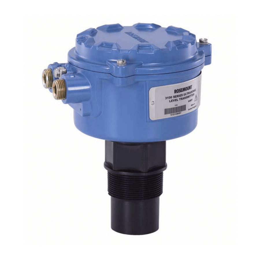
Rosemount 3100 Series
Ultrasonic Level Transmitter
Step 1: Mount the Transmitter
Step 2: Connect the Wiring
Step 3: Configure the Transmitter
www.rosemount.com
Rosemount 3100 Series
Start
Check Process Connections
Confirm Configuration
End
Advertisement
Table of Contents

Related Manuals for Emerson Rosemount 3100 Series


Summary of Contents for Emerson Rosemount 3100 Series
- Page 1 Quick Installation Guide 00825-0100-4840, Rev AB Rosemount 3100 Series January 2008 Rosemount 3100 Series Ultrasonic Level Transmitter Start Step 1: Mount the Transmitter Step 2: Connect the Wiring Step 3: Configure the Transmitter Check Process Connections Confirm Configuration www.rosemount.com...
-
Page 2: Important Notice
January 2008 © 2008 Rosemount Inc. All rights reserved. All marks property of owner. The Emerson logo is a trademark and service mark of Emerson Electric Co. Rosemount and the Rosemount logotype are registered trademarks of Rosemount Inc. PlantWeb is a registered trademark of one of the Emerson Process Management group of companies. - Page 3 • Avoid contact with the leads and terminals. High voltage that may be present on leads can cause electrical shock. • Make sure the power to the Rosemount 3100 Series transmitter is off and the lines to any other external power source are...
- Page 4 Quick Installation Guide 00825-0100-4840, Rev AB Rosemount 3100 Series January 2008 WARNING • The Integral Display and Push-buttons are only to be used for the purpose of installation, maintenance, or configuration. The enclosure cover is to be securely fitted at all other times, thus ensuring that the type of protection is not compromised.
- Page 5 Quick Installation Guide 00825-0100-4840, Rev AB Rosemount 3100 Series January 2008 1: M OUNT THE RANSMITTER Mounting considerations Figure 1. 1. Avoid mounting over objects, Max. 3° and disturbed flow. 2. Note maximum and minimum distances from tank wall Use non-metallic fitting / flange (see Figure 1, left side.)
- Page 6 Quick Installation Guide 00825-0100-4840, Rev AB Rosemount 3100 Series January 2008 Mounting with optional bracket kit Figure 4. Stainless steel bracket disc Long SelfTap Screw (3 Positions) Carbon steel (zinc plated) Note: Combined weight of bracket and disc is 16oz (0.5kg) approx.
- Page 7 Rosemount 3100 Series January 2008 2: C ONNECT IRING The Rosemount 3100 Series is a 2-wire loop-powered transmitter accepting power supplies as follows: • Model 3101: 12-30VDC • Model 3102: 12-40VDC • Model 3105: 12-40VDC (non-hazardous), 12-30VDC (hazardous). The transmitter requires shielded twisted pair wiring (18-12 AWG) that is suitable for the supply voltage and approved for use in hazardous areas.
-
Page 8: Intrinsically Safe Output
Quick Installation Guide 00825-0100-4840, Rev AB Rosemount 3100 Series January 2008 Figure 8. Intrinsically Safe Output Approved IS Barrier IS Parameters: Ui = 30 V, li = 120 mA, Pi = 0.82 W, Power Rosemount 3105 Li = 108 H, Ci = 0 nF... -
Page 9: Load Limitations
Quick Installation Guide 00825-0100-4840, Rev AB Rosemount 3100 Series January 2008 Load Limitations Figure 9. Non-Intrinsically Safe Installation: Non-Intrinsically Safe Installation: R (Ohms) R (Ohms) 1244 1244 (Model 3101) (Model 3102) U (V) U (V) Intrinsically Safe Installation: R (Ohms) -
Page 10: Configure The Transmitter
3: C ONFIGURE THE RANSMITTER Configuration of the Rosemount 3100 Series transmitter can be done with the Integral Display and Push-Buttons. Rosemount transmitter models 3102 and 3105 can use a Rosemount 3490 Series Control Unit, a 375 Field Communicator, or PC with AMS(TM) Suite: Intelligent Device Manager. - Page 11 Quick Installation Guide 00825-0100-4840, Rev AB Rosemount 3100 Series January 2008 Integral Display Menu (Model 3101)
- Page 12 Quick Installation Guide 00825-0100-4840, Rev AB Rosemount 3100 Series January 2008 Integral Display Menu (Model 3101) continued...
- Page 13 Quick Installation Guide 00825-0100-4840, Rev AB Rosemount 3100 Series January 2008 Integral Display Menus (Models 3102/3105) MAIN MENU...
- Page 14 Quick Installation Guide 00825-0100-4840, Rev AB Rosemount 3100 Series January 2008 Integral Display Menus (Models 3102/3105) continued... MAIN MENU...
- Page 15 Quick Installation Guide 00825-0100-4840, Rev AB Rosemount 3100 Series January 2008 Integral Display Menus (Models 3102/3105) continued... MAIN MENU...
- Page 16 Quick Installation Guide 00825-0100-4840, Rev AB Rosemount 3100 Series January 2008 Integral Display Menus (Models 3102/3105) continued... MAIN MENU...
-
Page 17: Engineering Menu
Quick Installation Guide 00825-0100-4840, Rev AB Rosemount 3100 Series January 2008 Integral Display Menus (Models 3102/3105) continued... ENGINEERING MENU... - Page 18 Quick Installation Guide 00825-0100-4840, Rev AB Rosemount 3100 Series January 2008 Integral Display Menus (Models 3102/3105) continued... ENGINEERING MENU...
- Page 19 Quick Installation Guide 00825-0100-4840, Rev AB Rosemount 3100 Series January 2008 Integral Display Menus (Models 3102/3105) continued... ENGINEERING MENU...
-
Page 20: Diagnostics Menu
Quick Installation Guide 00825-0100-4840, Rev AB Rosemount 3100 Series January 2008 Integral Display Menus (Models 3102/3105) continued... DIAGNOSTICS MENU... -
Page 21: Product Certifications
Quick Installation Guide 00825-0100-4840, Rev AB Rosemount 3100 Series January 2008 Product Certifications NOTE: A safety isolator such as a zener barrier is needed for intrinsic safety. Factory Mutual (FM) Approvals (Models 3101/3102) Factory Mutual (FM) Ordinary Location Approval G5 Project ID: 3024095... -
Page 22: Canadian Standards Association (Csa) Approvals
Standards Council of Canada (SCC). Special conditions for safe use: The power for the Rosemount 3100 Series must be supplied from a 3490 Series Control Unit, or from a class 2 or SELV source. (Model 3105) - Page 23 Quick Installation Guide 00825-0100-4840, Rev AB Rosemount 3100 Series January 2008 ATEX Intrinsically Safe Approval (Model 3105) I1 Certificate: Sira 06ATEX2260X Intrinsically Safe for II 1 G, EEx ia IIC Temperature Class: T4 (T -40°C to +60°C) T6 (T -40°C to +55°C) Ui = 30 V, li = 120 mA, Pi = 0.82 W, Li = 108 H, Ci = 0 nF...
- Page 24 Quick Installation Guide 00825-0100-4840, Rev AB Rosemount 3100 Series January 2008 IECEx Intrinsically Safe Approval (Model 3105) I7 Certificate: IECEx SIR 06.0068X Intrinsically Safe for Zone 0, Ex ia IIC Temperature Class: T4 (T -40°C to +60°C) T6 (T -40°C to +55°C) Ui = 30 V, li = 120 mA, Pi = 0.82 W, Li = 108 H, Ci = 0 nF...
Need help?
Do you have a question about the Rosemount 3100 Series and is the answer not in the manual?
Questions and answers