
Related Manuals for Emerson Rosemount 3100 Series


Summary of Contents for Emerson Rosemount 3100 Series
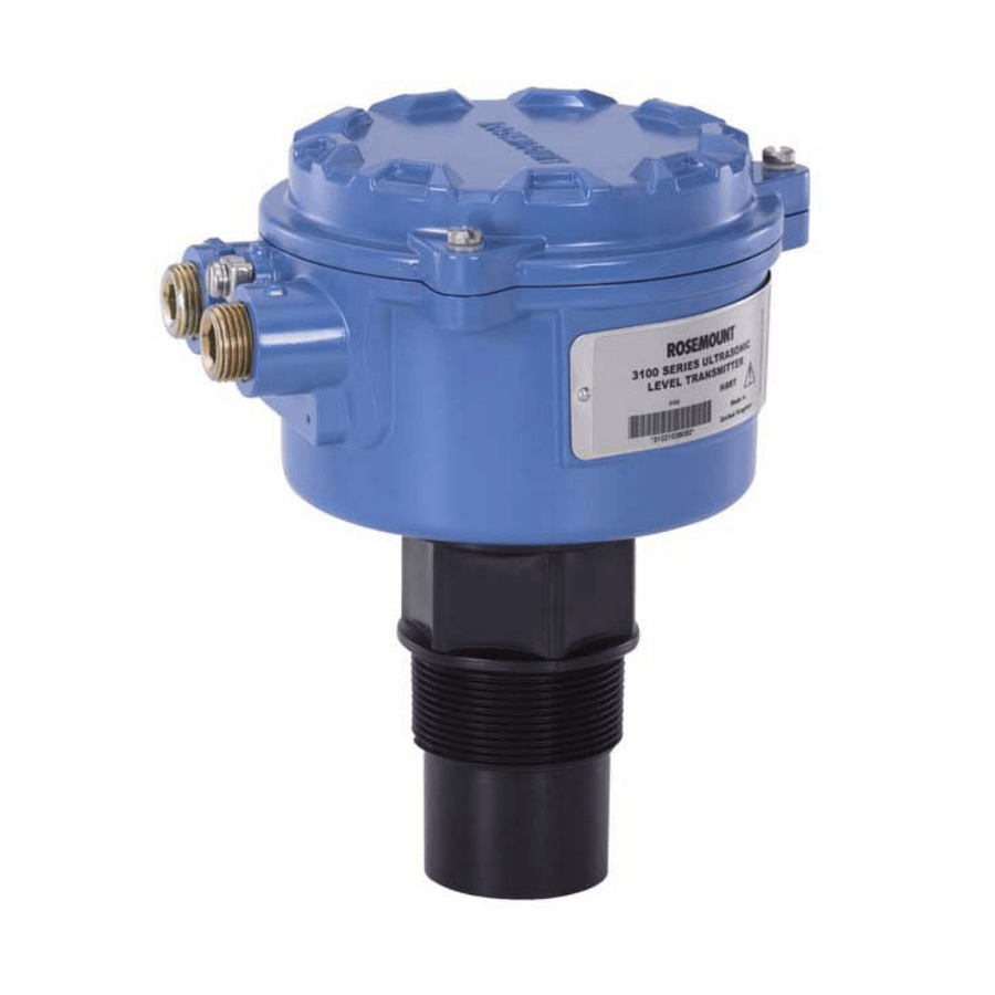
- Page 1 Reference Manual 00809-0100-4840, Rev. BA July 2008 Rosemount 3100 Series Ultrasonic Liquid Level Transmitters www.rosemount.com...
- Page 3 Rosemount and the Rosemount logotype are registered trademarks of Rosemount Inc. HART is a registered trademark of the HART Communication Foundation. Asset Management Solutions is a trademark of Emerson Process Management. Cover Photo: CoverPhoto_06/CoverPhoto_07 www.rosemount.com...
-
Page 5: Table Of Contents
Reference Manual 00809-0100-4840, Rev. BA Rosemount 3100 Series July 2008 Table of Contents SECTION 1 Safety Messages ......... 1-1 Manual Overview . - Page 6 Reference Manual 00809-0100-4840, Rev. BA Rosemount 3100 Series July 2008 Selecting the Duty (The 3102/3105)..... . . 4-12 Selecting the Units of Measurement (The 3102/3105) ..4-13 Setting the Correct Bottom Reference (The 3102/3105) .
- Page 7 Reference Manual 000809-0100-4840, Rev. BA Rosemount 3100 Series July 2008 Spare Parts ..........A-9 Accessories for The Rosemount 3101/3102/3105 .
- Page 8 Reference Manual 00809-0100-4840, Rev. BA Rosemount 3100 Series July 2008 P020 (Damping / Smoothing Time) ..... . . F-14 P021 (Lost Echo Delay) ....... . F-14 P022 (Lost Echo Action).
- Page 9 Reference Manual 00809-0100-4840, Rev. BA Rosemount 3100 Series July 2008 Section 1 Introduction Safety Messages ....... . . page 1-1 Manual Overview .
-
Page 10: Manual Overview
00809-0100-4840, Rev. BA Rosemount 3100 Series July 2008 MANUAL OVERVIEW This manual provides installation, configuration and maintenance information for the Rosemount 3100 Series ultrasonic level transmitters. Section 2: Transmitter Overview Section 3: Installation Section 4: Starting Up Section 5: Service and Troubleshooting... -
Page 11: Service Support
To expedite the return process outside of the United States, contact the nearest Emerson Process Management representative. Within the United States, call the Emerson Process Management Instrument and Valves Response Center using the toll-free number 1-800-654-RSMT (7768). This center, available 24 hours a day, will assist you with any needed information or materials. - Page 12 Reference Manual 00809-0100-4840, Rev. BA Rosemount 3100 Series July 2008...
-
Page 13: Theory Of Operation
System Architecture ......page 2-3 THEORY OF OPERATION The Rosemount 3100 Series transmitter is designed to be mounted above a liquid, and uses ultrasonic pulses to continuously measure the distance to the surface of the liquid. -
Page 14: Components Of The Transmitter
00809-0100-4840, Rev. BA Rosemount 3100 Series July 2008 COMPONENTS OF THE The Rosemount 3100 Series transmitter has a housing containing advanced electronics for signal processing, and terminals for connecting the external TRANSMITTER power supply. The electronics produces an ultrasonic signal from the transmitter face. -
Page 15: System Architecture
Rosemount 3100 Series July 2008 SYSTEM The Rosemount 3100 Series is loop-powered which means it uses the same two wires for both power supply and output signal. ARCHITECTURE The transmitter can be connected to any suitable 24 Vdc power source using two-core, shielded cable. - Page 16 Reference Manual 00809-0100-4840, Rev. BA Rosemount 3100 Series July 2008...
- Page 17 High voltage that may be present on leads could cause electrical shock: Avoid contact with leads and terminals. Make sure the main power to the Rosemount 3100 Series transmitter is off and the lines to any other external power source are disconnected or not powered while wiring.
-
Page 18: Before You Install
NOTE: The Rosemount 3100 Series is designed to be mounted in a non-metallic fitting or flange. The use of metallic fittings/flanges is not recommended. Please see “Accessories for The Rosemount 3101/3102/3105“ on page A-9. -
Page 19: Mechanical Installation
Reference Manual 00809-0100-4840, Rev. BA Rosemount 3100 Series July 2008 MECHANICAL INSTALLATION Mounting Guidelines: Considerations a) The transmitter should be mounted above the liquid surface using the 2-inch thread provided. (See “Mounting the Transmitter Above the Liquid Surface“ on page 3-5.) (See “Accessories for The Rosemount 3101/3102/3105“... -
Page 20: Liquid Surface Conditions
Reference Manual 00809-0100-4840, Rev. BA Rosemount 3100 Series July 2008 Figure 3-1. Min and max distances from vessel wall Max. 3° Use non-metallic fitting / flange Beam angle 6° max. C = 0.11m/m (1.3”/ft) C Min. = 0.3m (12”) Liquid Surface... -
Page 21: Mounting The Transmitter Above The Liquid Surface
Above the Liquid Surface transmitter body. NOTE: The Rosemount 3100 Series is designed to be mounted in a non-metallic fitting or flange. The use of metallic fittings/flanges is not recommended. To help installation, flange accessories and bracket kits are available from Emerson Process Management. - Page 22 Reference Manual 00809-0100-4840, Rev. BA Rosemount 3100 Series July 2008 Figure 3-2. Mounting the Rosemount 3100 Series Using a Nozzle/Stand-off Use non-metallic fitting / flange PTFE Tighten to a torque of 1.5 lbf.ft (2 Nm) ® (Teflon using the hexagon.
-
Page 23: Open Channel Flow Installations (The 3102/3105)
Reference Manual 00809-0100-4840, Rev. BA Rosemount 3100 Series July 2008 Open Channel Flow There are normally two distinct parts to an open channel flow measurement system; the primary element (flow structure) and the secondary element Installations (Head measurement instrumentation). For accurate open channel flow (The 3102/3105) measurement, both parts of the system must be installed accurately. - Page 24 'drown' (refer to relevant Standard for further information.) • The Rosemount 3100 Series has integral temperature compensation, and must be protected at all times from direct sunlight and any radiated heat. The Rosemount 3102 and Rosemount 3105 have the option of a Remote Temperature Sensor for temperature compensation (see page 3-14.)
-
Page 25: Electrical Installation
00809-0100-4840, Rev. BA Rosemount 3100 Series July 2008 ELECTRICAL INSTALLATION Connecting the The Rosemount 3100 Series is a two-wire loop-powered transmitter accepting power supplies as follows: Transmitter • The 3101: 12 to 30 Vdc • The 3102: 12 to 40 Vdc •... -
Page 26: Wiring For The Rosemount 3101
Reference Manual 00809-0100-4840, Rev. BA Rosemount 3100 Series July 2008 Wiring for The The Rosemount 3101 is not intrinsically safe, and is for use in non-hazardous (Ordinary Location) installations only. Rosemount 3101 Wire the transmitter as shown in Figure 3-7. -
Page 27: Wiring For The Rosemount 3102
Reference Manual 00809-0100-4840, Rev. BA Rosemount 3100 Series July 2008 Wiring for The The Rosemount 3102 is not intrinsically safe, and is for use in non-hazardous (Ordinary Location) installations only. Rosemount 3102 Wire the transmitter as shown in Figure 3-8. -
Page 28: Wiring For The Rosemount 3105
Push-buttons“ on page 4-2.) Wiring for The The Rosemount 3105 is for intrinsically safe installations. See Appendix B for the safety approvals and control drawings for the Rosemount 3100 Series. Rosemount 3105 NOTE! Make sure the power supply is off when connecting the transmitter. - Page 29 Reference Manual 00809-0100-4840, Rev. BA Rosemount 3100 Series July 2008 Figure 3-9. Wiring Diagram for the Rosemount 3105. Max 3000m (9750ft) Ground in the control room only Ø 4-8mm (0.15 - 0.31") Min. 12VDC 0VDC +12-40VDC (non I.S. application) Twisted-pair, screened +12-30VDC from Min.
-
Page 30: Remote Temperature Sensor
Reference Manual 00809-0100-4840, Rev. BA Rosemount 3100 Series July 2008 Remote Temperature The Rosemount 3102 and Rosemount 3105 accept input from a remote temperature sensor (see “Accessories for The Rosemount 3101/3102/3105“ Sensor on page A-9.) This is a thermistor-based temperature sensor designed for use with The 3102 and The 3105. - Page 31 Reference Manual 00809-0100-4840, Rev. BA Rosemount 3100 Series July 2008 Section 4 Starting up Safety Messages ....... . . page 4-1 Overview .
-
Page 32: Overview
Rosemount 3100 Series July 2008 OVERVIEW Rosemount 3100 Series liquid level transmitters are operated from a menu of parameters, each held in a specific memory location within the transmitter. The memory locations may be pictured as a matrix, and navigated for ↓... -
Page 33: Power Up
Reference Manual 00809-0100-4840, Rev. BA Rosemount 3100 Series July 2008 Power Up When the power is turned on, the transmitter takes several seconds to initialize. The display will run a set-up routine, first illuminating all display characters, and then showing the software revision number. Finally, a full set of zeros is displayed while the microprocessor identifies the correct return echo. -
Page 34: Programming The Rosemount 3101
Reference Manual 00809-0100-4840, Rev. BA Rosemount 3100 Series July 2008 PROGRAMMING Refer the Integral Display menu on a card tucked between the housing and body, and in Appendix C. THE ROSEMOUNT 3101 Display Units The display units are indicated by the position of the decimal point in the... -
Page 35: First Measurements (The 3101)
Reference Manual 00809-0100-4840, Rev. BA Rosemount 3100 Series July 2008 First Measurements With the transmitter installed and display units selected, the display will show what the instrument calculates as the liquid depth (level). This value is (The 3101) calculated by the microprocessor as being the difference between the distance-to-target being measured and the default value for the datum or bottom reference (b.rEF). -
Page 36: Setting The Bottom Reference (The 3101)
Reference Manual 00809-0100-4840, Rev. BA Rosemount 3100 Series July 2008 Setting the Bottom Screen display: b.rEF Reference (The 3101) NOTE: See Figure C-1 on page C-2 for a map of the programming menu structure and how to access all the menu options. -
Page 37: Setting The Output Damping (The 3101)
Reference Manual 00809-0100-4840, Rev. BA Rosemount 3100 Series July 2008 ↓ e) Press the green button repeatedly to edit the flashing digit. → Press the blue button to move to the next digit. The digit flashes to indicate it can be edited. -
Page 38: Selecting The Action On Alarm Condition (The 3101)
Reference Manual 00809-0100-4840, Rev. BA Rosemount 3100 Series July 2008 NOTE: See Figure C-1 on page C-2 for a map of the programming menu structure and how to access all the menu options. To change the output damping: ↓ a) If entering the menu system from the PV display, press the green button repeatedly until the “d”... -
Page 39: Setting 4 Ma And 20 Ma Levels Using Ranging (The 3101)
Reference Manual 00809-0100-4840, Rev. BA Rosemount 3100 Series July 2008 ↵ c) If this action is correct, press the red button and then the green button to get to the next menu option. → d) Press the blue button to start editing. The action flashes to indicate it can be edited. -
Page 40: Learn About Echoes From False Targets (The 3101)
Reference Manual 00809-0100-4840, Rev. BA Rosemount 3100 Series July 2008 b) Ensure the target is the 20 mA level and, with the display indicating that → level, press the blue button c) The display indicates the present 20 mA level setting, not the new level ↵... -
Page 41: Changing To Distance Mode (The 3101)
Reference Manual 00809-0100-4840, Rev. BA Rosemount 3100 Series July 2008 NOTE: When a false echo is stored, the transmitter sets up a 'window' around the false target and ignores any echo from that window, unless the echo received from the liquid surface is larger than the stored false echo. There may be no change in the transmitter output current while the liquid level moves through this window, which is equivalent to a distance of 8 in. -
Page 42: Programming The 3102 And The 3105
Reference Manual 00809-0100-4840, Rev. BA Rosemount 3100 Series July 2008 PROGRAMMING THE Menu structures for this section are in Appendix C (Integrated Display Menus) 3102 AND THE 3105 NOTE: If using a HART Master Device for programming The 3102 or The 3105, refer to the following sections for menu structures and parameters: •... -
Page 43: Selecting The Units Of Measurement (The 3102/3105)
Reference Manual 00809-0100-4840, Rev. BA Rosemount 3100 Series July 2008 ↓ e) Press the green button repeatedly to scroll through the list of duties. → Press the blue button to confirm the duty. The flashing then stops. ↵ g) If the new duty is correct, press the red button to save. -
Page 44: Setting The Correct Bottom Reference (The 3102/3105)
Reference Manual 00809-0100-4840, Rev. BA Rosemount 3100 Series July 2008 NOTE: ↓ • When using the green button to scroll through the list of measurement units, allow three seconds after each button press for the transmitter to check and display the selection. -
Page 45: Selecting A Profile (The 3102/3105)
Reference Manual 00809-0100-4840, Rev. BA Rosemount 3100 Series July 2008 g) Repeat steps (e) and (f) until the last digit is flashing, and edited as required. → h) Press the blue button to confirm the new b.rEF value. None of the digits should now be flashing. - Page 46 Reference Manual 00809-0100-4840, Rev. BA Rosemount 3100 Series July 2008 → b) Press the blue button to enter the “ProF” menu and display the present profile selection. ↵ c) If the selected profile is correct, press the red button to exit to the menu.
- Page 47 Reference Manual 00809-0100-4840, Rev. BA Rosemount 3100 Series July 2008 → Press the blue button to confirm the new profile. (The flashing stops.) ↵ g) If the new profile is correct, press the red button to save. The display changes to the next menu option.
- Page 48 Reference Manual 00809-0100-4840, Rev. BA Rosemount 3100 Series July 2008 Table 4-1. Profile options for flow Hmax Scale Factor 20 mA Point Metric Imperial Metric Imperial Power Metric Imperial Options Flow Structures (ft/in.) /hour) (GPM Factor (ft/in.) Flume 3/2 flow law...
-
Page 49: Power Factor For The Flow Law (The 3102/3105)
Reference Manual 00809-0100-4840, Rev. BA Rosemount 3100 Series July 2008 Power Factor for the Screen display: P.FACt Flow Law Factory default value: 1.000 (The 3102/3105) This menu is offered if the selected duty is Flow and a profile (e.g. “SPEC.C”) -
Page 50: Maximum Level Entry (The 3102/3105)
Reference Manual 00809-0100-4840, Rev. BA Rosemount 3100 Series July 2008 For a linear Contents duty, enter a scaling factor to convert the level measurement to a volume measurement. If the measurement units are “m”, enter the volume contained in 1 m of liquid height in the tank. If the units of measurements are “ft”, then enter the volume contained in 1 ft of liquid... -
Page 51: Maximum Flow Entry (The 3102/3105)
Reference Manual 00809-0100-4840, Rev. BA Rosemount 3100 Series July 2008 ↵ c) If the indicated value is correct, press the red button to exit to the menu. ↓.) (The “LEUEL @ max” re-appears. To get to the next menu, press →... -
Page 52: Maximum Contents (Volume) Entry (The 3102/3105)
Reference Manual 00809-0100-4840, Rev. BA Rosemount 3100 Series July 2008 Maximum Contents Screen display Cont @ max (Volume) Entry Factory default value 1.000 (The 3102/3105) This menu option is offered if the selected duty is Contents (Volume) and requires entry of the maximum contents of the vessel. -
Page 53: Setting The 20 Ma Point (The 3102/3105)
Reference Manual 00809-0100-4840, Rev. BA Rosemount 3100 Series July 2008 ↵ c) If the 4 mA point value is correct, press the red button to exit to the ↓.) menu. (The menu option “4” re-appears. To go to the next menu, press →... -
Page 54: Setting The Output Damping (The 3102/3105)
Reference Manual 00809-0100-4840, Rev. BA Rosemount 3100 Series July 2008 Setting the Output Screen display: Damping Factory default value: (The 3102/3105) The damping value is a time constant in seconds, and is applied as smoothing to the displayed PV and the output current. -
Page 55: Selecting The Alarm Condition Action (The 3102/3105)
Reference Manual 00809-0100-4840, Rev. BA Rosemount 3100 Series July 2008 Selecting the Alarm Screen display: Condition Action Factory default value: Hold (The 3102/3105) The Rosemount 3102 and Rosemount 3105 can signal an alarm condition if the target echo is lost for 900 seconds or more. The 900 seconds is factory set and is changeable in the field. -
Page 56: Setting The Relay On And Off Points (The 3102)
Reference Manual 00809-0100-4840, Rev. BA Rosemount 3100 Series July 2008 Setting the Relay On and The Rosemount 3102 has two integral signal relays. Both relays are the SPST (Single Pole, Single Throw) type. Off Points (The 3102) RL1 is factory-set to be a control relay. It may be set to energize at any value of PV, and de-energize at any other value of PV. -
Page 57: Setting The 4 And 20 Ma Levels Using Ranging (The 3102 And The 3105)
Reference Manual 00809-0100-4840, Rev. BA Rosemount 3100 Series July 2008 ↵ c) If the Off PV value is correct, press the red button to exit to the menu. (The menu option “r1 OFF” (or “r2 OFF”) re-appears. To get to the next ↓... -
Page 58: Final Checks
Reference Manual 00809-0100-4840, Rev. BA Rosemount 3100 Series July 2008 NOTE: This “SEt 20” menu option is in the programming menu. See Figure C-2 on page C-3 for a map of the menu structure and how to access the menu options. -
Page 59: Safety Messages
High voltage that may be present on leads could cause electrical shock. Avoid contact with leads and terminals. Make sure the main power to the Rosemount 3100 Series transmitter is off, and the lines to any other external power source are disconnected or not powered while wiring the transmitter. -
Page 60: Servicing
There are no spare parts for the Rosemount 3100 Series. If a problem persists, contact Emerson Process Management for advice. DIAGNOSTICS FOR... -
Page 61: Diagnostics For The 3102 And The 3105
Reference Manual 00809-0100-4840, Rev. BA Rosemount 3100 Series July 2008 DIAGNOSTICS FOR Menu structures for this section are in Appendix C (Integrated Display Menus) THE 3102 AND THE 3105 NOTE: If using a HART Master Device for programming The 3102 or The 3105, refer to the following sections for menu structures and parameters: •... -
Page 62: Loop Test (The 3102/3105)
Reference Manual 00809-0100-4840, Rev. BA Rosemount 3100 Series July 2008 ↓ 5. Press the green button to get to the next diagnostic data, “F”. This is the frequency at which the transmitter is operating, and should read between 49 and 58 kHz. - Page 63 Reference Manual 00809-0100-4840, Rev. BA Rosemount 3100 Series July 2008 → e) Press the blue button to move to the next digit. The digit flashes to indicate it can be edited. Repeat steps (d) and (e) until the last digit is flashing, and edited as required.
-
Page 64: Engineering Menu For The 3102 And 3105
Reference Manual 00809-0100-4840, Rev. BA Rosemount 3100 Series July 2008 ENGINEERING MENU Menu structures for this section are in Appendix C (Integrated Display Menus) FOR THE 3102 AND 3105 NOTE: If using a HART Master Device for programming The 3102 or The 3105, refer to the following sections for menu structures and parameters: •... -
Page 65: Setting Lost Echo Time (The 3102/3105)
Reference Manual 00809-0100-4840, Rev. BA Rosemount 3100 Series July 2008 → b) Press the blue button to enter the menu for “t.HoLd”. The display indicates the present threshold value. ↵ c) If the threshold value is correct, press the red button to exit to the menu. -
Page 66: Setting The Dead Band (The 3102/3105)
Reference Manual 00809-0100-4840, Rev. BA Rosemount 3100 Series July 2008 → d) Press the blue button to start the editing mode. The first digit flashes to indicate it can now be edited. ↓ e) Press the green button repeatedly to edit the flashing digit. -
Page 67: Setting The Frequency (The 3102/3105)
Reference Manual 00809-0100-4840, Rev. BA Rosemount 3100 Series July 2008 → If the new value is incorrect, press the blue button to exit to the menu. ↓ The “dEAd” re-appears; re-start at step (b) or press for the next menu. -
Page 68: Setting The Pulse Repetition Frequency (The 3102/3105)
Reference Manual 00809-0100-4840, Rev. BA Rosemount 3100 Series July 2008 Setting the Pulse Screen display: Repetition Frequency Factory default value: (The 3102/3105) The rate of pulses transmitted is set at a factory default value of once-per-second. The transmitter may be set to transmit faster or slower at selectable repetition rates between 0.5 and 2.0 times per second. -
Page 69: Setting Spike Rejection (The 3102/3105)
Reference Manual 00809-0100-4840, Rev. BA Rosemount 3100 Series July 2008 To change the valid echo count: a) After entering the “Eng” menu (see the note above), press the green ↓ button repeatedly until “Stir” is indicated. → b) Press the blue button to enter the stirrer (“Stir”) menu. -
Page 70: Learn About Echoes From False Targets (The 3102/3105)
Reference Manual 00809-0100-4840, Rev. BA Rosemount 3100 Series July 2008 Learn About Echoes Screen display: From False Targets The Rosemount 3102 and Rosemount 3105 has an easy-to-use “Lrn” (Learn) (The 3102/3105) routine that allows the instrument to learn up to four false echoes, which can then be ignored in future operations. -
Page 71: Setting The Ambient Temperature (The 3102/3105)
Reference Manual 00809-0100-4840, Rev. BA Rosemount 3100 Series July 2008 To clear all the stored false echoes: a) After entering the “Eng” menu (see the note above), press the green ↓ button repeatedly until “Lrn” is indicated. → b) Press the blue button to enter the “Lrn”... -
Page 72: Temperature Calibration (The 3102/3105)
Reference Manual 00809-0100-4840, Rev. BA Rosemount 3100 Series July 2008 ↵ If the new value is correct, press the red button to save. The display changes to the next menu option. The next menu is “t.CAL” if using the optional Remote Temperature Sensor to measure the air temperature. - Page 73 Reference Manual 00809-0100-4840, Rev. BA Rosemount 3100 Series July 2008 Loading Screen display: Ld.dEF Factory Default Values It may, occasionally, be necessary to re-set the transmitter parameters to (The 3102/3105) factory default values, particularly if the data already changed is in question.
-
Page 74: Changing The Base Units (The 3102/3105)
Reference Manual 00809-0100-4840, Rev. BA Rosemount 3100 Series July 2008 Changing the Base Units Screen display: b.unit (The 3102/3105) Factory default: metric (m) or imperial (ft) The transmitter may be re-configured to operate in a choice of base units: •... -
Page 75: Specifications
SPECIFICATIONS General Product Rosemount 3100 Series liquid level transmitters: Rosemount 3101: Level and Distance measurement. Rosemount 3102: Level, Distance, Volume, Open channel flow measurement, two integral signal relays. Rosemount 3105: Level, Distance, Volume, Open channel flow measurement for hazardous locations. - Page 76 Reference Manual 00809-0100-4840, Rev. BA Rosemount 3100 Series July 2008 Electrical Power supply Loop-powered (two-wire) Rosemount 3101: 12 to 30 Vdc Rosemount 3102: 12 to 40 Vdc Rosemount 3105: 12 to 40 Vdc (non-hazardous area), 12 to 30 Vdc (hazardous area).
-
Page 77: Temperature And Pressure Ratings
° ° ° F (-30 C) on The 3102/3105 Process temperature and pressure diagram for The Rosemount 3100 Series ® LOAD LIMITATIONS A HART Communicator requires a minimum load resistance of 250 Ohm within the loop in order to function properly. Communication with The Rosemount 3490 Universal Controller does not require additional resistance. -
Page 78: Dimensional Drawings
Reference Manual 00809-0100-4840, Rev. BA Rosemount 3100 Series July 2008 DIMENSIONAL DRAWINGS Figure A-1. Dimensions of the 3100 Series transmitter Ø6.7 in. (Ø170 mm) ½-14 NPT 5.7 in. cable entries (145 mm) 2.36 in. (60 mm) A/F hexagon 2.6 in. - Page 79 Reference Manual 00809-0100-4840, Rev. BA Rosemount 3100 Series July 2008 Figure A-2. 2-in. NPT/BSPT mounting bracket 2 in. NPT/BSPT 4.33 in. (110.0 mm) 2.95 in. (75.0 mm) 0.35 in. (8.9 mm) 2.26 in. (57.3) 2.24 in. 1.5 in. (57.0 mm) (38.0 )
-
Page 80: Ordering Information
Reference Manual 00809-0100-4840, Rev. BA Rosemount 3100 Series July 2008 ORDERING INFORMATION The 3101, Level of liquids Model Product Description 3101 Ultrasonic level transmitter Code Signal Output 4–20 mA Code Housing Material Polyurethane-covered Aluminum Code Conduit / Cable Threads ½–14 NPT M20 x 1.5 adapter... -
Page 81: The 3102, Level, Content (Volume) Or Flow Of Liquids
Reference Manual 00809-0100-4840, Rev. BA Rosemount 3100 Series July 2008 The 3102, Level, Content (Volume) or Flow of liquids Model Product Description 3102 Ultrasonic level transmitter with two integral relays Code Signal Output ® 4–20 mA with HART communication Code... -
Page 82: The 3105, Level, Content (Volume) Or Flow Of Liquids
Reference Manual 00809-0100-4840, Rev. BA Rosemount 3100 Series July 2008 The 3105, Level, Content (Volume) or Flow of liquids Model Product Description 3105 Ultrasonic level transmitter for hazardous areas Code Signal Output ® 4–20 mA with HART communication Code Housing Material... -
Page 83: Spare Parts
Reference Manual 00809-0100-4840, Rev. BA Rosemount 3100 Series July 2008 SPARE PARTS Accessories for The Rosemount 3101/3102/3105 Code Accessory/Spare Accessories 03100-1001-0001 2-in. NPT to 2-in. ANSI Class 150 PVC Flange 03100-1001-0002 2-in. NPT to 3-in. ANSI Class 150 PVC Flange 03100-1001-0003 2-in. - Page 84 Reference Manual 00809-0100-4840, Rev. BA Rosemount 3100 Series July 2008 A-10...
-
Page 85: Safety Messages
Reference Manual 00809-0100-4840, Rev. BA Rosemount 3100 Series July 2008 Appendix B Product Certifications Safety Messages ....... . . page B-1 EU Conformity . -
Page 86: Eu Conformity
Standards Council of Canada (SCC). Special conditions for safe use: 1. For the CSA approval, power for the Rosemount 3100 Series must be supplied from a Rosemount 3490 Control Unit, or a class 2 or SELV source. -
Page 87: Hazardous Locations Certifications
Reference Manual 00809-0100-4840, Rev. BA Rosemount 3100 Series July 2008 HAZARDOUS Transmitters that have the following labels attached have been certified to comply with the requirements of the approval agencies noted. LOCATIONS CERTIFICATIONS Factory Mutual (FM) The 3105 only: Approvals Project ID: 3024095 Intrinsically Safe for Class I, Division 1, Groups A, B, C, and D. -
Page 88: Canadian Standards Association (Csa) Approvals
Reference Manual 00809-0100-4840, Rev. BA Rosemount 3100 Series July 2008 Canadian Standards The 3105 only: Association (CSA) Project ID: 07CSA1878089X Approvals Intrinsically Safe for Class I, Division 1, Groups A, B, C, and D. Intrinsically Safe for Class I, Zone 0, Ex ia IIC. -
Page 89: Atex Intrinsically Safe Approval
Reference Manual 00809-0100-4840, Rev. BA Rosemount 3100 Series July 2008 ATEX Intrinsically Safe Certificate: Sira 06ATEX2260X Intrinsically Safe for II 1 G, EEx ia IIC Approval Temperature Class: T4 (T -40°C to +60°C) T6 (T -40°C to +55°C) Ui = 30 V, li = 120 mA, Pi = 0.82 W, Li = 108 μH, Ci = 0 μF... -
Page 90: Iecex Intrinsically Safe Approval
Reference Manual 00809-0100-4840, Rev. BA Rosemount 3100 Series July 2008 IECEx Intrinsically Safe Certificate: IECEx SIR 06.0068X Approval Intrinsically Safe for Zone 0, Ex ia IIC Temperature Class: T4 (T -40°C to +60°C) T6 (T -40°C to +55°C) Ui = 30 V, li = 120 mA, Pi = 0.82 W, Li = 108 μH, Ci = 0 μF... -
Page 91: National Supervision And Inspection Centre (Nepsi) Intrinsically
Reference Manual 00809-0100-4840, Rev. BA Rosemount 3100 Series July 2008 National Supervision and Certificate: GYJ081008X Inspection Centre (NEPSI) Intrinsic Safety: Ex ia IIC T4/T6 Intrinsically Safe Approval Ui = 30 V, Ii = 120 mA, Pi = 0.82 W, Ci ≈ 0 nF, Li = 108 μ... - Page 92 Reference Manual 00809-0100-4840, Rev. BA Rosemount 3100 Series July 2008 Safety Parameters: Power supply terminals (1, 2) Ui = 30 V, Ii = 120 mA, Pi = 0.82 W, Ci ≈ 0 nF, Li = 108 μH Sensor terminals (7, 8) Uo = 30 V, Io = 8.42 mA, Po = 63 mW, Co = 66 nF, Lo = 502 mH...
-
Page 93: Approval Drawings
Reference Manual 00809-0100-4840, Rev. BA Rosemount 3100 Series July 2008 APPROVAL DRAWINGS This section contains Factory Mutual installation drawings and Canadian Standards installation drawings. You must follow the installation guidelines presented in order to maintain certified ratings for installed transmitters. - Page 94 Reference Manual 00809-0100-4840, Rev. BA Rosemount 3100 Series July 2008 Figure B-5. System Control Drawing for hazardous location installation of intrinsically safe and non-incendive FM approved apparatus. B-10...
- Page 95 Reference Manual 00809-0100-4840, Rev. BA Rosemount 3100 Series July 2008 Figure B-6. System Control Drawing for hazardous location installation of intrinsically safe and non-incendive CSA approved apparatus. B-11...
- Page 96 Reference Manual 00809-0100-4840, Rev. BA Rosemount 3100 Series July 2008 Figure B-7. EC Declaration of Conformity RMD 1062 Rev A Sheet 1 of 3 B-12...
- Page 97 Reference Manual 00809-0100-4840, Rev. BA Rosemount 3100 Series July 2008 Sheet 2 of 3 B-13...
- Page 98 Reference Manual 00809-0100-4840, Rev. BA Rosemount 3100 Series July 2008 Sheet 3 of 3 B-14...
- Page 99 Reference Manual 00809-0100-4840, Rev. BA Rosemount 3100 Series July 2008 Appendix C Integrated Display Menus Menus on The 3101 ....... page C-2 Menus on The 3102 And The 3105 .
-
Page 100: Menus On The 3101
Reference Manual 00809-0100-4840, Rev. BA Rosemount 3100 Series July 2008 MENUS ON THE 3101 Figure C-1. Menu Programming on The 3101 PV D isp lay D ist an ce Ech o Size (Echo Size ) ( PV D isplay ) (D istance ) (b .r EF ) -
Page 101: Menus On The 3102 And The 3105
Reference Manual 00809-0100-4840, Rev. BA Rosemount 3100 Series July 2008 MENUS ON THE 3102 AND THE 3105 Figure C-2. Main Menu Programming on The 3102/3105... - Page 102 Reference Manual 00809-0100-4840, Rev. BA Rosemount 3100 Series July 2008 Figure C-3. Diagnostics Menu on The 3102/3105...
- Page 103 Reference Manual 00809-0100-4840, Rev. BA Rosemount 3100 Series July 2008 Figure C-4. Engineering Menu on The 3102/3105...
- Page 104 Reference Manual 00809-0100-4840, Rev. BA Rosemount 3100 Series July 2008...
-
Page 105: Introduction
Introduction ........page D-1 Rosemount 3100 Series Transmitter (3102/3105) ..page D-2... - Page 106 Reference Manual 00809-0100-4840, Rev. BA Rosemount 3100 Series July 2008...
- Page 107 Reference Manual 00809-0100-4840, Rev. BA Rosemount 3100 Series July 2008...
- Page 108 Reference Manual 00809-0100-4840, Rev. BA Rosemount 3100 Series July 2008...
-
Page 109: Introduction
Do not perform any service other than those contained in this manual unless qualified. As a matter of routine, the Rosemount 3100 Series transmitter and all other equipment in your tank should be shut off prior to entering the tank. - Page 110 Reference Manual 00809-0100-4840, Rev. BA Rosemount 3100 Series July 2008 Figure E-1. HART Communicator Menu Tree Online Menu 1 Tag 2 Bottom Reference 1 Basic Setup 3 Upper Range Value 1 Bottom Reference 4 Lower Range Value 1 CONFIGURE /...
- Page 111 Reference Manual 00809-0100-4840, Rev. BA Rosemount 3100 Series July 2008 Continued from previous page 1 Power Control 2 Pulse Rate 3 Echoes Needed 4 Threshold 1 Time Online Menu 5 Threshold 1 Size 6 Target Pulses 7 Target Frequency 5 Advanced...
- Page 112 Reference Manual 00809-0100-4840, Rev. BA Rosemount 3100 Series July 2008 Continued from previous page 1 Model Code 2 Manufacturer Online Menu 3 Serial Number 4 Maximum Temperature 5 Minimum Temperature 1 Summary 2 DEVICE DIAGNOSTICS 2 Failed 1 Failed Status...
- Page 113 Reference Manual 00809-0100-4840, Rev. BA Rosemount 3100 Series July 2008 Table E-1. HART Fast Key Sequences Function HART Fast Key Base Units 1, 3, 5, 8 Bottom Reference 1, 1, 1, 2 Primary Value (PV) 3, 1, 1 Level (Secondary Variable)
- Page 114 Reference Manual 00809-0100-4840, Rev. BA Rosemount 3100 Series July 2008...
-
Page 115: Introduction
Reference Manual 00809-0100-4840, Rev. BA Rosemount 3100 Series July 2008 Appendix F Parameters accessed over HART Communications Introduction ........page F-1 Transmitter Action Parameters (The 3102 And 3105) . -
Page 116: Transmitter Action Parameters (The 3102 And 3105
Reference Manual 00809-0100-4840, Rev. BA Rosemount 3100 Series July 2008 TRANSMITTER ACTION NOTE: For relevant menu structures, refer to Appendix D or Appendix E, whichever PARAMETERS is appropriate for your HART Master Device. (THE 3102 AND 3105) Parameter: When the transmitter is shipped from the factory, the default factory settings... -
Page 117: Parameter: Learn False Echo
Reference Manual 00809-0100-4840, Rev. BA Rosemount 3100 Series July 2008 Parameter: Select the Learn False Echo menu option. Options are to quit to the previous menu, or start the learning process. LEARN FALSE ECHO The transmitter can learn that the present distance measurement is calculated from an echo off a false target, and the false echo can be ignored. -
Page 118: Parameter: Factory Use
Reference Manual 00809-0100-4840, Rev. BA Rosemount 3100 Series July 2008 Parameter: This parameter is for factory use only. FACTORY USE... -
Page 119: Transmitter P*** Parameters (The 3102 And 3105
Reference Manual 00809-0100-4840, Rev. BA Rosemount 3100 Series July 2008 TRANSMITTER P*** NOTE: For relevant menu structures, refer to Appendix D or Appendix E, whichever PARAMETERS is appropriate for your HART Master Device. (THE 3102 AND 3105) The 'P' prefixed parameters (e.g. P010) are for adjusting the operational set-up of the transmitter. -
Page 120: P011 (Tank Shape
Reference Manual 00809-0100-4840, Rev. BA Rosemount 3100 Series July 2008 P011 (Tank Shape) P011 Description This selects the shape of a vessel or open channel, and establishes the linear or non-linear relationship between the live liquid level (height) and the Process Value (PV) derived from that level. - Page 121 Reference Manual 00809-0100-4840, Rev. BA Rosemount 3100 Series July 2008 To derive up to 10 profile points, it is necessary to have tabulated or graphical data to relate the required Process Value (PV) to Liquid Height. Figure F-2 on page F-7 shows an example graph of PV versus Liquid Height.
- Page 122 Reference Manual 00809-0100-4840, Rev. BA Rosemount 3100 Series July 2008 Each live level (height) measurement is converted into a percentage (0 to 100%), which is proportional to the maximum height (P014). In graph terms, the converted percentage corresponds to an X ordinate on the X-axis.
- Page 123 Reference Manual 00809-0100-4840, Rev. BA Rosemount 3100 Series July 2008 P011 = “Horizontal Cyl Flat” (Horizontal cylinder, flat ends) This setting is applicable when volume of content measurements involving a horizontally oriented cylindrical vessel with a constant diameter is required –...
- Page 124 Reference Manual 00809-0100-4840, Rev. BA Rosemount 3100 Series July 2008 P011 = “Flume/Weir-3/2” This setting is applicable when flow measurements involving an open channel with a flume or weir profile is required. The rate of flow per second is calculated by:...
- Page 125 Reference Manual 00809-0100-4840, Rev. BA Rosemount 3100 Series July 2008 P011 = “V-Notch-5/2” This setting is applicable when flow measurements involving an open channel with a V-notch weir is required. The rate of flow through a V-notch is calculated using:...
-
Page 126: P012 (Pv Units
Reference Manual 00809-0100-4840, Rev. BA Rosemount 3100 Series July 2008 P012 (PV Units) P012 Description: Use this to select alternative Display Units of the PV, which are reported to the HART Master Device e.g. Rosemount 3490 Series Control Unit. NOTE: Selecting alternative Display Units does not re-scale the PV value. -
Page 127: P014 (Profile Height Or Power
Reference Manual 00809-0100-4840, Rev. BA Rosemount 3100 Series July 2008 P014 P014 Description (Profile Height or Power) When calculating the volume of liquid contents in an ideal horizontal cylinder or sphere, P014 is set to the diameter, as shown by Figure F-4 on page F-9. -
Page 128: P020 (Damping / Smoothing Time
Reference Manual 00809-0100-4840, Rev. BA Rosemount 3100 Series July 2008 P020 (Damping / P020 Description Smoothing Time) This defines the time constant of the exponential smoothing used on the output Process Value (PV), and is entered as a value in seconds. The pulse repetition frequency of the transmitter is approximately one pulse per second, which means that the system response time cannot be faster than this. -
Page 129: P022 (Lost Echo Action
Reference Manual 00809-0100-4840, Rev. BA Rosemount 3100 Series July 2008 P022 (Lost Echo Action) P022 Description This defines what happens to the PV output when a Lost Echo condition exists, which is after the Lost Echo Delay period (P021) has elapsed. -
Page 130: P024 (Speed Of Sound
Reference Manual 00809-0100-4840, Rev. BA Rosemount 3100 Series July 2008 P024 (Speed of Sound) P024 Description P024 is for entering the speed of sound of the gas above the liquid surface (ullage gas) in a closed vessel, at a temperature of 32 °F (0 °C). -
Page 131: P025 (Temperature
Reference Manual 00809-0100-4840, Rev. BA Rosemount 3100 Series July 2008 P025 (Temperature) P025 Description This is for temperature correcting of the speed of sound entered in P024. The corrected speed of sound is displayed in D914. For automatic (dynamic) corrections using the integrated temperature sensor, select the AUTO option. -
Page 132: P041 (Pulse Repeat
Reference Manual 00809-0100-4840, Rev. BA Rosemount 3100 Series July 2008 P041 (Pulse Repeat) P041 Description The nominal rate of repetition for ultrasonic pulses from the transmitter is one pulse per second. If two transmitters were located within the same vessel, it is possible this would allow ultrasonic pulses from one unit to be received by the other. -
Page 133: P045 (Target Frequency
Reference Manual 00809-0100-4840, Rev. BA Rosemount 3100 Series July 2008 P045 (Target Frequency) P045 Description P045 sets the frequency used for transmitting an ultrasonic pulse. The optimum frequency depends on the characteristics of the transmitter piezoelectric crystal, which are affected by temperature. -
Page 134: P070 To P072 (Relay 1 Setting-Up
Reference Manual 00809-0100-4840, Rev. BA Rosemount 3100 Series July 2008 Figure F-7. Tank Geometry Abbreviations: SRP = Sensor Reference Point UPSRP = User Preferred SRP Data processing sequence: 1. Echoes are processed that occur between P023 (Upper Blanking) and P063 (Lower Blanking). -
Page 135: P073 To P075 (Relay 2 Setting-Up
Reference Manual 00809-0100-4840, Rev. BA Rosemount 3100 Series July 2008 P073 to P075 P073 to P075 Description (Relay 2 Setting-up) P073 RL2 Mode P074 RL2 PV On Point P075 RL2 PV Off Point On The Rosemount 3102, relay RL2 is a SPST (Single Pole, Single Throw) type. -
Page 136: Transmitter D*** Parameters (The 3102 And 3105
Reference Manual 00809-0100-4840, Rev. BA Rosemount 3100 Series July 2008 TRANSMITTER D*** NOTE: For relevant menu structures, refer to Appendix D or Appendix E, whichever PARAMETERS is appropriate for your HART Master Device. (THE 3102 AND 3105) The 'D' prefixed parameters (e.g. D900) monitor the transmitter operation. -
Page 137: D906 (Current Output
Reference Manual 00809-0100-4840, Rev. BA Rosemount 3100 Series July 2008 NOTE: When the poll address is a non-zero number, the transmitter is in multi-drop mode and the current output is fixed at 4 mA. D906 (Current Output) D906 Description This displays the current used for the Current Output. -
Page 138: D915 (Temperature
D919 (Transmit Power) D919 Description If this feature is enabled on the Rosemount 3100 Series ultrasonic transmitter, the transmitter optimizes the power needed for pulse transmission. The lower the number, the less power being transmitted. The higher the number, the more power being transmitted. -
Page 139: D962 (Hart Revision
Reference Manual 00809-0100-4840, Rev. BA Rosemount 3100 Series July 2008 D962 (HART Revision) D962 Description This is the major revision number of the standard for the HART communications protocol. D963 (Txr Specific D963 Description Command Revision) This is the minor revision number of the commands supported by the transmitter. - Page 140 Reference Manual 00809-0100-4840, Rev. BA Rosemount 3100 Series July 2008 F-26...
- Page 144 00809-0100-4840, Rev. BA Rosemount 3100 Series July 2008 The Emerson logo is a trademark and service mark of Emerson Electric Co. Rosemount and the Rosemount logotype are registered trademarks of Rosemount Inc. Teflon is a registered trademark of DuPont Performance Elastomers.
Need help?
Do you have a question about the Rosemount 3100 Series and is the answer not in the manual?
Questions and answers