
Related Manuals for Vega FIBERTRAC 32


Summary of Contents for Vega FIBERTRAC 32
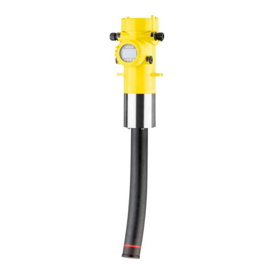
- Page 1 Quick setup guide Radiometric sensor for continuous level and interface measurement FIBERTRAC 32 Four-wire 4 … 20 mA/HART Document ID: 62071...
-
Page 2: Table Of Contents
Operating Instructions Manual as well as the Safety Manual that comes with instruments with SIL qualification. These manuals are available on our homepage. Operating instructions FiberTRAC 32 - Four-wire 4 … 20 mA/ HART: Document-ID 37428 Editing status of the quick setup guide: 2021-11-25 FIBERTRAC 32 • Four-wire 4 … 20 mA/HART... -
Page 3: For Your Safety
All operations described in this documentation must be carried out only by trained, qualified personnel authorised by the plant operator. During work on and with the device, the required personal protective equipment must always be worn. Appropriate use FIBERTRAC 32 is a sensor for continuous level measurement. You can find detailed information about the area of application in chapter " Product description". Operational reliability is ensured only if the instrument is properly used according to the specifications in the operating instructions manual as well as possible supplementary instructions. -
Page 4: Eu Conformity
That is why we have introduced an environment management system with the goal of continuously improving company environmental pro- tection. The environment management system is certified according to DIN EN ISO 14001. Please help us fulfil this obligation by observing the environmental instructions in this manual: • Chapter " Packaging, transport and storage" • Chapter " Disposal" FIBERTRAC 32 • Four-wire 4 … 20 mA/HART... -
Page 5: Product Description
Move to " www.vega.com" and enter in the search field the serial number of your instrument. Alternatively, you can access the data via your smartphone: • Download the VEGA Tools app from the " Apple App Store" or the " Google Play Store" • Scan the QR-code on the type label of the device or •... -
Page 6: Corresponding Source Container
General instructions for When handling radioactive sources, unnecessary radiation exposure radiation protection must be avoided. An unavoidable radiation exposure must be kept as low as possible. Take note of the following three important measures: Fig. 2: Measures for protection against radioactive radiation Shielding Time Distance FIBERTRAC 32 • Four-wire 4 … 20 mA/HART... - Page 7 Control areas are areas in which the local dose rate exceeds a certain value. Only persons who undergo official dose monitoring are allowed into these control areas. You can find the respectively valid limit values for control areas in the guideline of the respective authority (in Ger- many, for example, the radiation protection ordinance). We are at your disposal for further information concerning radiation protection and regulations in other countries. FIBERTRAC 32 • Four-wire 4 … 20 mA/HART...
-
Page 8: Mounting
These are mainly: • Active measuring component • Process fitting • Process seal Process conditions in particular are: • Process pressure • Process temperature • Chemical properties of the medium • Abrasion and mechanical influences FIBERTRAC 32 • Four-wire 4 … 20 mA/HART... -
Page 9: Mounting Instructions
The following mounting information is applicable as long as there is nothing else specified in the "Source Sizing" document. Fig. 3: Level measurement in a storage tank Measuring range Measurement length (L1, L2) FIBERTRAC 32 • Four-wire 4 … 20 mA/HART... - Page 10 You can find information on protective barriers and the mounting of the corresponding source container in the operating instructions manual of the source container, e.g. VEGASOURCE. You can mount the FIBERTRAC 32 with the housing head upward or downward. When the housing head is mounted downward, the hous- ing itself is more easily accessible. Fasten the sensor in such a way that it cannot fall out of the holder. If necessary, provide the sensor with a support from below.
- Page 11 Make sure that the red marking lines directly join the measuring range of the next FIBERTRAC 32. Mount the FIBERTRAC 32 in such a way that the detector hose is directly in the radiated area of the source container. Mount the FIBERTRAC 32 preferably side by side and make sure that no detec- tor hose is hidden by another sensor.
- Page 12 If these measures are not sufficient to maintain the max. ambient temperature, you could consider using the water or air cooling system we offer for FIBERTRAC 32. The cooling system must also be included in the calculations for the measuring point. Contact our specialists regarding the dimensioning of the cooling. FIBERTRAC 32 • Four-wire 4 … 20 mA/HART...
-
Page 13: Connecting To Power Supply
2. Loosen compression nut of the cable gland and remove blind plug 3. Remove approx. 10 cm (4 in) of the cable mantle, strip approx. 1 cm (0.4 in) of insulation from the ends of the individual wires 4. Insert the cable into the sensor through the cable entry FIBERTRAC 32 • Four-wire 4 … 20 mA/HART... - Page 14 9. Tighten the compression nut of the cable entry gland. The seal ring must completely encircle the cable 10. Screw the housing lid back on The electrical connection is finished. Information: The terminal blocks are pluggable and can be detached from the electronics. To do this, loosen the two lateral locking levers of the terminal block with a small screwdriver. When loosening the locking, the terminal block is automatically squeezed out. It must snap in place when re-inserted. FIBERTRAC 32 • Four-wire 4 … 20 mA/HART...
-
Page 15: Connection - Level Measurement
Terminals for the external display and adjustment unit Contact pins for the display and adjustment module or interface adapter Instruments with intrinsically safe current output You can find detailed information on the explosion-protected versions (Ex-ia, Ex-d) in the Ex-specific safety instructions. These safety MGC = Multi Gauge Communication FIBERTRAC 32 • Four-wire 4 … 20 mA/HART... - Page 16 Terminals for intrinsically safe signal output 4 … 20 mA/HART (active) Contact pins for the display and adjustment module or interface adapter Terminals for the external display and adjustment unit Ground terminal MGC = Multi Gauge Communication FIBERTRAC 32 • Four-wire 4 … 20 mA/HART...
-
Page 17: Connection - Level Detection
Contact pins for the display and adjustment module or interface adapter Connection to a PLC If inductive loads or stronger currents are switched through, the gold plating on the relay contact surface will be permanently damaged. The contact is then no longer suitable for switching low-voltage circuits. MGC = Multi Gauge Communication FIBERTRAC 32 • Four-wire 4 … 20 mA/HART... - Page 18 Signal input 4 … 20 mA Switching input for NPN transistor 5 Switching input floating Transistor output Interface for sensor-sensor communication (MGC) Setting the bus address for sensor-sensor communication (MGC) MGC = Multi Gauge Communication FIBERTRAC 32 • Four-wire 4 … 20 mA/HART...
-
Page 19: Connection - Summation
Secondary". Select under the menu item " Setup - Application" the function "Summation Secondary". The address setting (MGC) on the Secondary instruments can be freely selected. Only the address "99" is reserved for the Primary instrument. FIBERTRAC 32 • Four-wire 4 … 20 mA/HART... - Page 20 Fig. 16: Electronics and connection compartment with cascading of several instruments. M Primary instrument S Secondary instrument Information: For example, a radial connection would be also possible as an alter- native. Take note of the polarity. The selection of the two terminal pairs is individual. FIBERTRAC 32 • Four-wire 4 … 20 mA/HART...
-
Page 21: Set Up With The Display And Adjustment Module
Disassembly is carried out in reverse order. The display and adjustment module is powered by the sensor, an ad- ditional connection is not necessary. Fig. 17: Insert display and adjustment module Note: If you intend to retrofit the instrument with a display and adjustment module for continuous measured value indication, a higher lid with an inspection glass is required. Parameter adjustment - Summation Secondary Cascading To measure the level in very high vessels, multiple instruments can be cascaded. FIBERTRAC 32 • Four-wire 4 … 20 mA/HART... - Page 22 " Point level" or " Summation Secondary". In this menu item you can activate the function of the current output. Outputs When the output is activated, the instrument remains in its function as a Secondary, but the 4 … 20 mA output of the FIBERTRAC 32 can be also used als single instrument. When the output is active, the instrument has the complete function- ality of a level measuring instrument. In this case, continue reading under " Parameter adjustment/Level measurement". FIBERTRAC 32 • Four-wire 4 … 20 mA/HART...
- Page 23 5 Set up with the display and adjustment module FIBERTRAC 32 • Four-wire 4 … 20 mA/HART...
-
Page 24: Supplement
0.2 … 1.5 mm² (AWG 24 … 16) Voltage supply Operating voltage 24 … 65 V DC (-15 … +10 %) or 24 … 230 V AC (-15 … +10 %), 50/60 Hz Reverse voltage protection Available Max. power consumption 6 VA (AC); 4 W (DC) FIBERTRAC 32 • Four-wire 4 … 20 mA/HART... - Page 25 Notes FIBERTRAC 32 • Four-wire 4 … 20 mA/HART...
- Page 26 Notes FIBERTRAC 32 • Four-wire 4 … 20 mA/HART...
- Page 27 Notes FIBERTRAC 32 • Four-wire 4 … 20 mA/HART...
- Page 28 Subject to change without prior notice © VEGA Grieshaber KG, Schiltach/Germany 2021 VEGA Grieshaber KG Am Hohenstein 113 Phone +49 7836 50-0 77761 Schiltach E-mail: info.de@vega.com...
Need help?
Do you have a question about the FIBERTRAC 32 and is the answer not in the manual?
Questions and answers