
Subscribe to Our Youtube Channel
Related Manuals for Vega VEGABAR 39


Summary of Contents for Vega VEGABAR 39
- Page 1 Operating Instructions Pressure sensor with metallic measuring cell VEGABAR 39 Two-wire 4 … 20 mA Document ID: 57089...
-
Page 2: Table Of Contents
Preparations ........................37 Connecting ........................37 Parameter adjustment ....................38 10 Menu overview ........................39 10.1 Display and adjustment unit (on site) ................39 10.2 VEGA Tools app and DTM (Bluetooth) ................40 VEGABAR 39 • Two-wire 4 … 20 mA... - Page 3 14.5 Trademark ........................64 Safety instructions for Ex areas: Take note of the Ex specific safety instructions for Ex applications. These instructions are attached as documents to each instrument with Ex approval and are part of the operating instructions. Editing status: 2022-08-25 VEGABAR 39 • Two-wire 4 … 20 mA...
-
Page 4: About This Document
Symbols used Document ID This symbol on the front page of this instruction refers to the Docu- ment ID. By entering the Document ID on www.vega.com you will reach the document download. Information, note, tip: This symbol indicates helpful additional infor- mation and tips for successful work. -
Page 5: For Your Safety
During work on and with the device, the required personal protective equipment must always be worn. Appropriate use The VEGABAR 39 is a pressure transmitter for process pressure and hydrostatic level measurement. You can find detailed information about the area of application in chapter " Product description". Operational reliability is ensured only if the instrument is properly used according to the specifications in the operating instructions manual as well as possible supplementary instructions. - Page 6 2 For your safety Installations in the US shall comply with the relevant requirements of the National Electrical Code (ANSI/NFPA 70). Installations in Canada shall comply with the relevant requirements of the Canadian Electrical Code. VEGABAR 39 • Two-wire 4 … 20 mA...
-
Page 7: Product Description
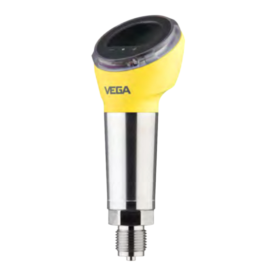
The respective scope of delivery results from the order specification. Scope of this operating This operating instructions manual applies to the following instrument instructions versions: • Hardware version from 1.0.0 • Software version from 1.3.0 VEGABAR 39 • Two-wire 4 … 20 mA... - Page 8 3 Product description Constituent parts Fig. 1: Components of VEGABAR 39 1 Process fitting Electronics housing Ventilation/pressure compensation Plug connector LED illuminated ring Display/adjustment unit Type label The type label contains the most important data for identification and use of the instrument. VEGABAR 39 • Two-wire 4 … 20 mA...
-
Page 9: Principle Of Operation
• Enter serial number manually in the VEGA Tools app (available free of charge in the respective stores) Principle of operation Measured variables The VEGABAR 39 is suitable for the measurement of the following process variables: • Process pressure •... - Page 10 3 Product description Fig. 3: Process pressure measurement VEGABAR 39 Application area VEGABAR 39 is suitable for applications in virtually all industries. It is used for the measurement of the following pressure types. • Gauge pressure • Absolute pressure •...
-
Page 11: Adjustment
1) For cleaning procedures "free of oil, grease and silicone for oxygen applica- tions" also for measuring range 100 bar VEGABAR 39 • Two-wire 4 … 20 mA... -
Page 12: Packaging, Transport And Storage
Transport Transport must be carried out in due consideration of the notes on the transport packaging. Nonobservance of these instructions can cause damage to the device. VEGABAR 39 • Two-wire 4 … 20 mA... -
Page 13: Accessories
Welded sockets are used to connect the devices to the process. and hygienic adapter Threaded and hygienic adapters enable simple adaptation of devices with standard threaded fittings to process-side hygiene connections. Mounting accessories The suitable mounting accessories for VEGABAR 39 includes si- phons, blocking valves and measuring instrument holders. VEGABAR 39 • Two-wire 4 … 20 mA... -
Page 14: Mounting
Protect your instrument against moisture ingress through the following ture measures: • Use a suitable connection cable (see chapter " Connecting to power supply") • Tighten the cable gland or plug connector VEGABAR 39 • Two-wire 4 … 20 mA... - Page 15 (e.g. through cleaning processes) and on cooled or heated vessels. Make sure that the degree of contamination specified in chapter " Technical data" meets the existing ambient conditions. Ventilation and pressure Ventilation and pressure compensation for VEGABAR 39 are provided compensation by an air-permeable, moisture-blocking filter element. Note: In case of horizontal mounting, turn the housing so that the filter ele- ment points downward after the instrument is installed. This provides better protection against buildup.
-
Page 16: Process Pressure Measurement
Mount the instrument above the measuring point Possible condensation can then drain off into the process line. Fig. 9: Measurement setup for process pressure measurement of gases in pipelines VEGABAR 39 Blocking valve Pipeline In vapours Keep the following in mind when setting up the measuring system: • Connect via a siphon VEGABAR 39 • Two-wire 4 … 20 mA... - Page 17 Keep the following in mind when setting up the measuring system: • Mount the instrument below the measuring point The effective pressure line is always filled with liquid and gas bubbles can bubble up to the process line. Fig. 11: Measurement setup for process pressure measurement of liquids in pipelines VEGABAR 39 Blocking valve Pipeline VEGABAR 39 • Two-wire 4 … 20 mA...
-
Page 18: Level Measurement
Keep the following in mind when setting up the measuring system: • Mount the instrument below the min. level • Do not mount the instrument close to the filling stream or emptying area • Mount the instrument so that it is protected against pressure shocks from the stirrer Fig. 12: Measurement setup for level measurement VEGABAR 39 • Two-wire 4 … 20 mA... -
Page 19: Connecting To Power Supply
ISO 4400 1. Loosen the screw on the rear of the plug connector 2. Remove the plug connector and seal from VEGABAR 39 3. Remove the plug insert from the plug housing VEGABAR 39 • Two-wire 4 … 20 mA... - Page 20 Plug insert Plug seal 7. Snap the plug insert into the plug housing and insert the sensor seal 8. Plug the plug insert with seal to VEGABAR 39 and tighten the screw The electrical connection is finished. ISO 4400 plug with Proceed as follows: hinged cover 1.
- Page 21 9. Tighten the screws on the strain relief and cable entry 10. Hook in the cover and push onto the plug connection, tighten cover screw 11. Plug the plug insert with seal to VEGABAR 39 and tighten the screw VEGABAR 39 • Two-wire 4 … 20 mA...
-
Page 22: Wiring Plan - Two-Wire 4
Fig. 18: Wiring plan - two-wire 4 … 20 mA - plug according to ISO 4400 Voltage supply and signal output Contact, plug connector Function/Polarity Voltage supply, signal output/+ Voltage supply, signal output/- Free Electrically connected with metal housing VEGABAR 39 • Two-wire 4 … 20 mA... -
Page 23: Switch-On Phase
Internal check of the electronics • The output signal jumps to the set fault current The current measured value is then output on the signal cable. 2) Internal bridge between contact 2 and 3 VEGABAR 39 • Two-wire 4 … 20 mA... -
Page 24: Access Protection
" Ac- cess protection". If this document is lost, the emergency device code can be retrieved from your personal contact person after legitimation. VEGABAR 39 • Two-wire 4 … 20 mA... -
Page 25: Storing The Codes In Myvega
" PINs and Codes". This greatly simplifies the use of additional adjust- ment tools, as all Bluetooth access and device codes are automati- cally synchronized when connected to the " myVEGA" account VEGABAR 39 • Two-wire 4 … 20 mA... -
Page 26: Set Up With The Integrated Display And Adjustment Unit
Change parameter values upwards Switching between the individual measured value windows Navigation in the menu items, backwards Change parameter values downwards [+] and [-] Jump to next higher menu simultane- Interrupt input ously VEGABAR 39 • Two-wire 4 … 20 mA... -
Page 27: Measured Value And Menu Item Display
2 Measured value as digital value with unit 3 Measuring cell temperature Sensor-TAG Menu item display The menu items are displayed according to the following diagram: 1.0000 bar SPAN Fig. 22: Display menu item 1 Menu item code acc. to VDMA 24574-1 Actual parameter value 3 Menu item name VEGABAR 39 • Two-wire 4 … 20 mA... -
Page 28: Parameter Adjustment
The menu item Span (final value) defines the pressure value at the output current 20 mA. Menu item code: • Parameter: • Pressure value Extended functions, These menu items allow access to the menu areas " Extended func- diagnosis tions" or " Diagnosis". VEGABAR 39 • Two-wire 4 … 20 mA... - Page 29 • Time value Offset correction The installation position of the device can shift the measured value minimally (offset). The offset correction compensates this measured value shift. The measured value that should currently be displayed is entered (manual offset correction). With relative pressure transmitters, an automatic offset to 0.0000 bar can alternatively be carried out. Note: With automatic offset correction, the current measured value must not be influenced by product coverage or static pressure. VEGABAR 39 • Two-wire 4 … 20 mA...
- Page 30 Pressure unit lection made determines the displayed unit in the menu items " Zero/ Span" and " Offset correction" as well as " Accept value". 3) LRV: Lower Range Value, URV: Upper Range Value VEGABAR 39 • Two-wire 4 … 20 mA...
- Page 31 Bluetooth unlock code on the information sheet " Emergency unlock codes" also supplied. Menu item code: • VEGABAR 39 • Two-wire 4 … 20 mA...
- Page 32 " Emergency unlock codes" also supplied. Note: With protected parameter adjustment, adjustment via the VEGA Tools app as well as PACTware/DTM and other systems is also blocked. Reset During a reset, parameter settings made by the user are reset to the values of the basic setting or the delivery status (see chapter "...
- Page 33 This menu item displays the number of parameter changes made. counter Menu item code: • Peak indicator In this menu item, the min. and max. values for pressure, measuring cell temperature and electronics temperature are displayed. Menu item code: • VEGABAR 39 • Two-wire 4 … 20 mA...
- Page 34 7 Set up with the integrated display and adjustment unit • Information: To reset the peak indicator, the VEGA Tools app or PACTware/DTM is required. Sensor information This menu item displays the hardware and software status as well as the serial number of the device.
-
Page 35: Setup With Smartphone/Tablet (Bluetooth)
• Operating system: Android 5.1 or newer • Bluetooth 4.0 LE or newer Download the VEGA Tools app from the " Apple App Store", " Goog- le Play Store" or " Baidu Store" to your smartphone or tablet. Connecting Connecting Start the adjustment app and select the function "... -
Page 36: Sensor Parameter Adjustment
Display", " Diagnosis" and others. The selected menu item, recognisable by the colour change, is dis- played in the right half. Fig. 24: Example of an app view - Setup measured values VEGABAR 39 • Two-wire 4 … 20 mA... -
Page 37: Setup With Pc/Notebook (Bluetooth)
Enter Bluetooth access For authentication, enter in the next menu window the 6-digit code Bluetooth access code: Fig. 25: Enter Bluetooth access code VEGABAR 39 • Two-wire 4 … 20 mA... -
Page 38: Parameter Adjustment
(DTM) according to FDT standard are required. The latest PACTware version as well as all available DTMs are compiled in a DTM Collec- tion. The DTMs can also be integrated into other frame applications according to FDT standard. Fig. 26: Example of a DTM view - Adjustment current output VEGABAR 39 • Two-wire 4 … 20 mA... -
Page 39: Menu Overview
Protection of the parameterization Reset Diagnostics Menu item Code acc. to Delivery status VDMA 24574-1 Status Parameter modification counter Min. value peak indicator Last values Max. value peak indicator Sensor information INF, HW, SW VEGABAR 39 • Two-wire 4 … 20 mA... -
Page 40: Vega Tools App And Dtm (Bluetooth)
Red, yellow, green …, individual Green colour selection, no signalling Flashing Yes, no Note: With the 360° status indication switched on, the lighting of the display and adjustment unit is deactivated or vice versa. 6) Signalling of process pressure ranges by colour and flashing VEGABAR 39 • Two-wire 4 … 20 mA... - Page 41 Sensor features (DTM) Sensor characteristics Features of the instrument version 7) When the display lighting is on, the 360° status display is deactivated or vice versa. VEGABAR 39 • Two-wire 4 … 20 mA...
-
Page 42: Diagnostics And Servicing
24 hour service hotline Should these measures not be successful, please call in urgent cases the VEGA service hotline under the phone no. +49 1805 858550. The hotline is also available outside normal working hours, seven days a week around the clock. -
Page 43: Diagnosis, Fault Messages
" Diagnostics" via the respective adjustment module. 8) Signalling of process pressure ranges by colour and flashing, adjustable via VEGA Tools app or PACTware/DTM. 9) Delivery status; adjustable via VEGA Tools app or PACTware/DTM VEGABAR 39 • Two-wire 4 … 20 mA... - Page 44 Hardware error in the area of the meas- Send instrument for repair uring cell no measured value available F017 Adjustment not within specification Change adjustment Adjustment span too small F036 Failed or interrupted software update Repeat software update no operable sensor software VEGABAR 39 • Two-wire 4 … 20 mA...
-
Page 45: Software Update
Fault in internal communication with the Restart display No communication with the Send instrument for repair main controller 11.5 Software update The device software is updated via Bluetooth. The following components are required: VEGABAR 39 • Two-wire 4 … 20 mA... -
Page 46: How To Proceed If A Repair Is Necessary
Attach the completed form and, if need be, also a safety data sheet outside on the packaging • Ask the agency serving you to get the address for the return ship- ment. You can find the agency on our homepage. VEGABAR 39 • Two-wire 4 … 20 mA... -
Page 47: Dismount
If personal data is stored on the old device to be disposed of, delete it before disposal. If you have no way to dispose of the old instrument properly, please contact us concerning return and disposal. VEGABAR 39 • Two-wire 4 … 20 mA... -
Page 48: Certificates And Approvals
NE 21 – Electromagnetic compatibility of equipment • NE 43 – Signal level for fault information from measuring transduc- Exception: Versions with measuring ranges from 250 bar. These are subject of the EU Pressure Device Directive. VEGABAR 39 • Two-wire 4 … 20 mA... -
Page 49: Environment Management System
DIN EN ISO 14001. Help us to meet these requirements and observe the environmental instructions in the chapters " Packaging, transport and storage", " Disposal" of this operating instructions. VEGABAR 39 • Two-wire 4 … 20 mA... -
Page 50: Supplement
Ʋ Contact surface German silver Ʋ Plug seal Silicone Weight approx. 0.25 kg (0.55 lbs) 11) Transmission liquid with measuring ranges up to 40 bar. With measuring ranges from 100 bar dry measuring cell. VEGABAR 39 • Two-wire 4 … 20 mA... - Page 51 0 … 5 bar/0 … 500 kPa +20 bar/+2000 kPa 0 bar abs. 0 … 10 bar/0 … 1000 kPa +40 bar/+4000 kPa 0 bar abs. 12) Data on overload capability apply for reference temperature. VEGABAR 39 • Two-wire 4 … 20 mA...
- Page 52 -20 … +95 % Ʋ Span -120 … +120 % Maximum permissible Turn Down Unlimited (recommended 20 : 1) Switch-on phase Start-up time with operating voltage U ≤ 2 s Starting current for run-up time ≤ 3.6 mA VEGABAR 39 • Two-wire 4 … 20 mA...
- Page 53 Ʋ Air pressure 860 … 1060 mbar/86 … 106 kPa (12.5 … 15.4 psi) Determination of characteristics Limit point adjustment according to IEC 61298-2 Characteristic curve Linear 13) Depending on medium and temperature VEGABAR 39 • Two-wire 4 … 20 mA...
- Page 54 Class 4M8 acc. to IEC 60271-3-4 (5 g at 4 … 200 Hz) Impacts (mechanical shock) Class 6M4 acc. to IEC 60271-3-6 (50 g, 2.3 ms) Impact resistance IK06 acc. to IEC 62262 14) 0 … +100 °C (+32 … +212 °F) VEGABAR 39 • Two-wire 4 … 20 mA...
- Page 55 0 °C (32 °F) 90 °C 100 °C (194 °F) (212 °F) Fig. 31: Temperature derating VEGABAR 39, with activated Bluetooth communication Process temperature Ambient temperature SIP process temperature Device configuration suitable for vapour, i.e. measuring cell seal EPDM or FFKM (Perlast G74S), previous CIP cleaning up to max. +80 °C (+176 °F): Vapour stratification up to Ʋ...
- Page 56 Display and adjustment unit, Bluetooth, IO-Link Bluetooth interface Bluetooth standard Bluetooth 5.0 Frequency 2.402 … 2.480 GHz Max. emitted power +2.2 dBm Max. number of participants 19) Depending on the instrument version VEGABAR 39 • Two-wire 4 … 20 mA...
- Page 57 Reaction time transistor output with ≤ 10 ms switching relevant change of the process variable total Damping (63 % of the input variable) 0 … 9 s, adjustable 21) Depending on medium and temperature VEGABAR 39 • Two-wire 4 … 20 mA...
- Page 58 Plug according to ISO 4400 with IDC method of termination Altitude above sea level 5000 m (16404 ft) Protection class Pollution degree 22) Illuminated display and adjustment unit or activated 360° status display VEGABAR 39 • Two-wire 4 … 20 mA...
-
Page 59: Dimensions
40 mm (1.38") (1.57") 36 mm (1.42") 66 mm (2.60") Fig. 33: Connection technology VEGABAR 39 M12 x 1 plug connector Plug connector according to ISO 4400 Plug connector according to ISO 4400 with hinged cover VEGABAR 39 • Two-wire 4 … 20 mA... - Page 60 ø 5 mm ø 3 mm ( 0.20 ") ( 0.12 ") Fig. 34: VEGABAR 39, threaded fitting not front-flush DU Thread G½ (EN 837), manometer connection C2 Thread M20 x 1.5 (EN 837), manometer connection LF Thread ½ NPT, inside ¼ NPT (ASME B1.20.1) LY Thread ½ NPT (ASME B1.20.1) TI Thread ¼ NPT (ASME B1.20.1) TJ Thread G¼ (ISO 228-1) VEGABAR 39 • Two-wire 4 … 20 mA...
- Page 61 ( 1.57 ") ( 2.17 ") ( 2.17 ") Fig. 35: VEGABAR 39, threaded fitting front-flush C3 Thread G½ (ISO 228-1) N9 Thread G¾ (DIN 3852-E) C5 Thread G1 (ISO 228-1) DA Thread G1½ (DIN 3852-A) C9 Thread 1½ NPT (ASME B1.20.1) VEGABAR 39 • Two-wire 4 … 20 mA...
- Page 62 SW 41 mm (1.61") (1.61") ø 40 mm ø 40 mm ( 1.57 ") ( 1.57 ") Fig. 36: VEGABAR 39, cone/extension fitting DH Thread G1 (ISO 228-1), cone 40° LX Thread G1 (ISO 228-1), hygienic design AL Thread M30 x 1.5 (DIN 13) VEGABAR 39 • Two-wire 4 … 20 mA...
- Page 63 FB SMS DN 51 PN 6 E7 Ingold connection PN 10 FR Varivent N50-40 PN 25 EZ Collar socket DN 40 PN 40 (DIN 11851) E2 Collar socket DN 40 PN 40 (DIN 11864-1, Form A) VEGABAR 39 • Two-wire 4 … 20 mA...
-
Page 64: Industrial Property Rights
Les lignes de produits VEGA sont globalement protégées par des droits de propriété intellec- tuelle. Pour plus d'informations, on pourra se référer au site www.vega.com. VEGA lineas de productos están protegidas por los derechos en el campo de la propiedad indus- trial. Para mayor información revise la pagina web www.vega.com. - Page 65 Notes VEGABAR 39 • Two-wire 4 … 20 mA...
- Page 66 Notes VEGABAR 39 • Two-wire 4 … 20 mA...
- Page 67 Notes VEGABAR 39 • Two-wire 4 … 20 mA...
- Page 68 Subject to change without prior notice © VEGA Grieshaber KG, Schiltach/Germany 2022 VEGA Grieshaber KG Am Hohenstein 113 Phone +49 7836 50-0 77761 Schiltach E-mail: info.de@vega.com...
Need help?
Do you have a question about the VEGABAR 39 and is the answer not in the manual?
Questions and answers