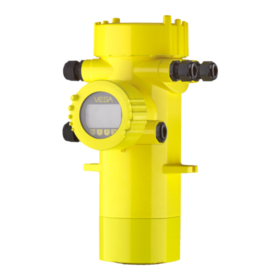
Summary of Contents for Vega PROTRAC Series
- Page 1 Operating Instructions Supplementary electronics PROTRAC sensors PT30ZE Document ID: 63552...
-
Page 2: Table Of Contents
Contents Contents About this document ....................... 3 Function ........................... 3 Target group ........................3 Symbols used........................3 For your safety ......................... 4 Authorised personnel ....................... 4 Appropriate use ........................ 4 Approvals ......................... 4 Environmental instructions ....................4 Product description ......................... 5 3.1 Configuration ........................ -
Page 3: About This Document
Symbols used Document ID This symbol on the front page of this instruction refers to the Docu- ment ID. By entering the Document ID on www.vega.com you will reach the document download. Information, note, tip: This symbol indicates helpful additional infor- mation and tips for successful work. -
Page 4: For Your Safety
If the instrument comes with approvals, the associated approval documents of the sensor must always be noted. They are included with the delivery but can also be downloaded under www.vega.com via " VEGA Tools" and " Search" as well as via " Downloads" and " Approvals". Environmental instructions Protection of the environment is one of our most important duties. -
Page 5: Product Description
3 Product description Product description 3.1 Configuration Scope of delivery The scope of delivery encompasses: • Supplementary electronics for PROTRAC sensors • Documentation – This operating instructions manual – If necessary, further certificates Principle of operation Application area The supplementary electronics module PT30ZE is a replacement module for PROTRAC sensors with double chamber housing: •... - Page 6 3 Product description • Storage and transport Storage and transport temperature see chapter " Supplement - temperature Technical data - Ambient conditions" • Relative humidity 20 … 85 % Supplementary electronics • PROTRAC sensors...
-
Page 7: Mounting
4 Mounting Mounting Installation procedure Installation procedure The supplementary electronics is installed in the adjustment and con- nection compartment. The following illustration shows the position of the adjustment and connection compartment in the double chamber housing. Fig. 1: Position of adjustment and connection compartment ( supplementary electronics) and electronics and connection compartment (sensor electronics) Electronics and connection compartment (sensor electronics) Adjustment and connection compartment (supplementary electronics) -
Page 8: Electronics Versions
4 Mounting 2. Loosen the two holding screws (3) of the supplementary electron- ics with a screwdriver (Torx size T 10 or slot size 4) 3. Pull the previous supplementary electronics out by using the dismounting tool (2). 4. Insert the new supplementary electronics module (1) carefully. 5. Screw in the two holding screws (3) and tighten them 6. - Page 9 4 Mounting 4 … 20 mA/HART - De- vices with intrinsically safe current output 4...20mA Display 6 7 8 Fig. 4: Adjustment and connection compartment with supplementary electronics - 4 … 20 mA/HART - Devices with intrinsically safe current output Supplementary electronics Dismounting tool Screws (2 pcs.)
- Page 10 4 Mounting Profibus PA, Foundation Fieldbus - Devices with intrinsically safe signal output Display 6 7 8 Fig. 6: Adjustment and connection compartment with supplementary electronics - Profibus PA, Foundation Fieldbus - Devices intrinsically safe signal output Supplementary electronics Dismounting tool Screws (2 pcs.) Supplementary electronics •...
-
Page 11: Maintenance
5 Maintenance Maintenance How to proceed if a repair is necessary You can find an instrument return form as well as detailed information about the procedure in the download area of our homepage. By doing this you help us carry out the repair quickly and without having to call back for needed information. In case of repair, proceed as follows: •... -
Page 12: Dismount
6 Dismount Dismount Dismounting steps Warning: Before dismounting, be aware of dangerous process conditions such as e.g. pressure in the vessel or pipeline, high temperatures, cor- rosive or toxic media etc. Take note of chapters " Mounting" and " Connecting to voltage sup- ply" and carry out the listed steps in reverse order. Disposal The instrument consists of materials which can be recycled by spe- cialised recycling companies. -
Page 13: Supplement
7 Supplement Supplement Technical data Technical data The technical data are listed in the operating instructions manual of the respective device. Supplementary electronics • PROTRAC sensors... - Page 14 Notes Supplementary electronics • PROTRAC sensors...
- Page 15 Notes Supplementary electronics • PROTRAC sensors...
- Page 16 Subject to change without prior notice © VEGA Grieshaber KG, Schiltach/Germany 2020 VEGA Grieshaber KG Phone +49 7836 50-0 Am Hohenstein 113...


Need help?
Do you have a question about the PROTRAC Series and is the answer not in the manual?
Questions and answers