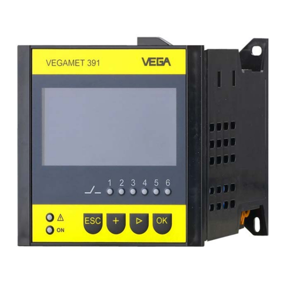
Vega VEGAMET 391 Operating Instructions Manual
Signal conditioning and display instrument for level sensors 4...20 ma/hart
Hide thumbs
Also See for VEGAMET 391:
- Operating instructions manual (68 pages) ,
- Supplementary instructions manual (64 pages) ,
- Operating instructions manual (60 pages)

Related Manuals for Vega VEGAMET 391


Summary of Contents for Vega VEGAMET 391
-
Page 1: Operating Instructions
Operating Instructions Signal conditioning and display instrument for level sensors VEGAMET 391 4 … 20 mA/HART Document ID: 36032... -
Page 2: Table Of Contents
..........................42 Pump control 1/2 (run time controlled) ................43 Pump control 3/4 (sequentially controlled) ..............47 Tendency recognition ..................... 50 Flow measurement ......................51 9 Maintenance and fault rectification ..................54 Maintenance ........................54 VEGAMET 391 • 4 … 20 mA/HART... - Page 3 11.2 Overview applications/functionality ................62 11.3 Dimensions ........................63 11.4 Industrial property rights ....................64 11.5 Trademark ........................64 Supplementary documentation Information: Supplementary documents appropriate to the ordered version come with the delivery. You can find them listed in chapter "Product descrip- tion". Editing status: 2017-09-04 VEGAMET 391 • 4 … 20 mA/HART...
-
Page 4: About This Document
This arrow indicates a single action. Sequence of actions Numbers set in front indicate successive steps in a procedure. Battery disposal This symbol indicates special information about the disposal of bat- teries and accumulators. VEGAMET 391 • 4 … 20 mA/HART... -
Page 5: For Your Safety
During work on and with the device the required personal protective equipment must always be worn. Appropriate use VEGAMET 391 is a universal signal conditioning instrument and power supply unit for connection of a 4 … 20 mA/HART sensor. You can find detailed information about the area of application in chapter "Product description". -
Page 6: Safety Label On The Instrument
Ex-approved instruments. 2.9 Overfill protection according to WHG In Germany the WHG (Water Resource Act) stipulates an overfill protection for systems that deal with substances hazardous to water. An appropriately certified sensor is the prerequisite for such protec- tion. The VEGAMET 391 fulfils the construction and testing principles for overfill protection systems. This is certified by the TÜV (Techni- cal Control Board) statement "PP 5003/09". You can download this document from our homepage under "Downloads - Approvals - Signal conditioning instruments - Overfill protection". VEGAMET 391 • 4 … 20 mA/HART... -
Page 7: Environmental Instructions
That is why we have introduced an environment management system with the goal of continuously improving company environmental pro- tection. The environment management system is certified according to DIN EN ISO 14001. Please help us fulfil this obligation by observing the environmental instructions in this manual: • Chapter "Packaging, transport and storage" • Chapter "Disposal" VEGAMET 391 • 4 … 20 mA/HART... -
Page 8: Product Description
Serial number of the instrument • Data matrix code for VEGA Tools app Serial number The type label contains the serial number of the instrument. With it you can find the following data on our homepage: • Product code of the instrument (HTML) VEGAMET 391 • 4 … 20 mA/HART... -
Page 9: Principle Of Operation
On instruments with one of the optional interfaces (RS232/Ethernet), the measured values can be retrieved via modem or network and displayed by means of a web browser or VEGA Inventory System. It is also possible to send measured values and messages via e-mail/ SMS. -
Page 10: Packaging, Transport And Storage
USB interface or one of the optional interfaces (RS232/Ethernet). Further instructions for setting up the web server and e-mail functions can be found in the online help of PACTware or the VEGAMET 391 DTMs as well as the operating instructions manual "RS232/Ethernet connection". Packaging, transport and storage Packaging Your instrument was protected by packaging during transport. -
Page 11: Mounting
If the instrument is mounted via screws or carrier rail, it must always be inside a switching cabinet or protective case. A VEGAMET 391 in Ex version is an auxiliary, intrinsically safe instru- ment and may not be installed in explosion-endangered areas. - Page 12 Carrier rail mounting 1. Fasten the mounting plate to the instrument with the four en- closed hexagon socket screws. 2. Screw the carrier rail adapter to the mounting plate with the four enclosed Phillips-head screws. VEGAMET 391 • 4 … 20 mA/HART...
- Page 13 4 Mounting Fig. 4: Carrier rail mounting Hexagon socket screws Mounting plate Carrier rail adapter Phillips head screws VEGAMET 391 • 4 … 20 mA/HART...
-
Page 14: Connecting To Power Supply
(low impedance). If potential equalisation currents are expected, the screen connection on the side of VEGAMET 391 must be made via a ceramic capacitor (e. g. 1 nF, 1500 V). The low frequency potential equalisation currents are thus suppressed, but the protective effect against high frequency interference signals remains. -
Page 15: Connection Procedure
The VEGAMET 391 can also be looped into the existing circuit like a normal ammeter. Note: With a VEGAMET 391 in Ex version, the passive input is not available for approval technical reasons. Connection procedure Move on to electrical connection and proceed as follows: 1. -
Page 16: Wiring Plan
11 Measurement data input (passive input), not with Ex-ia version 12 Digital input 1 … 4 13 Common ground for digital input 1 … 4 14 4 … 20 mA/HART sensor (two-wire version) VEGAMET 391 • 4 … 20 mA/HART... - Page 17 11 Measurement data input (passive input), not with Ex-ia version 12 Digital input 1 … 4 13 Common ground for digital input 1 … 4 14 4 … 20 mA/HART sensor (four-wire version) 15 Power supply for four-wire sensor VEGAMET 391 • 4 … 20 mA/HART...
-
Page 18: Setup With The Integrated Display And Adjustment Unit
Adjustment system Function The integrated display and adjustment unit is used for measured value display, adjustment and diagnosis of VEGAMET 391. The indication and adjustment are carried out via four keys and a clear, graphic-capable display with background lighting. The adjustment menu with selectable language is clearly structured and enables easy setup. -
Page 19: Setup Steps
USB interface or one of the optional interfaces (RS232/Ethernet). Further instructions for setting up the web server and e-mail functions are stated in the online help of PACTware or the VEGAMET 391 DTMs as well as the supplementary instructions manual "RS232/Ethernet connection". Switch-on phase After being switched on, VEGAMET 391 first of all carries out a short self-check. - Page 20 … • Display: Includes settings for the displayed measured value, language and brightness of the background lighting • Diagnosis Includes information on device status, error messages, input current, digital inputs VEGAMET 391 • 4 … 20 mA/HART...
- Page 21 Select the requested menu item via the respective keys and confirm with [OK]. Device settings - Device- You can assign an unambiguous name to VEGAMET 391 via the Device-TAG. This function is recommended when several instruments are implemented and a good documentation of larger systems is required.
- Page 22 4 … 20 signal. An adjustment in the sensor influences directly the input variable of VEGAMET 391. Only carry out the adjustment on one instrument, either on VEGAMET 391 or on the sensor. The adjustment in VEGAMET 391 is always car- ried out in mA (analogue transmission). Digital HART transmission For transmission via HART, VEGAMET 391 must be informed which sensor value should be used for further processing.
- Page 23 With radar, ultrasonic and guided microwave this is always the distance in metres or feet "m(d)" or "ft(d)", and with pres- sure transmitters it is e.g. "bar" or "psi". The following illustrations and examples relate to the min./max. ad- justment of a radar sensor with HART communication. VEGAMET 391 • 4 … 20 mA/HART...
- Page 24 Corresponding linearisation curves are preprogrammed for these vessels. They represent the correlation between the level percentage and vessel volume. By activating the appropriate curve, the volume percentage of the vessel is displayed VEGAMET 391 • 4 … 20 mA/HART...
- Page 25 (safe currentless state), relay is switched on again when the max. level is exceeded (switch-on point > switch- off point) • Pump control: With several pumps having the same function, the pumps will be alternately switch on and off according to the adjust- able criteria VEGAMET 391 • 4 … 20 mA/HART...
- Page 26 4 … 20 mA or inverted. The reaction in case of failure can also be adapted to the requirements. The measured variable you refer to can also be selected. → Carry out your settings via the appropriate keys and save with [OK]. VEGAMET 391 • 4 … 20 mA/HART...
- Page 27 • Spanish • Russian • Italian • Dutch → Carry out your settings via the appropriate keys and save with [OK]. Display - Brightness In the menu item "Display - Brightness", the brightness of the back- ground lighting can be continuously adjusted. VEGAMET 391 • 4 … 20 mA/HART...
- Page 28 Access protection of the DTM adjustment via the USB/Ethernet/ RS232 interface by means of a password (can be only activated via DTM) • Encryption of the DTM data transmission with connection via Ethernet/RS232 interface VEGAMET 391 • 4 … 20 mA/HART...
- Page 29 In mode HART Multidrop, an address from 1 … 15 is assigned to the sensor. By doing so, the current is fix limited to 4 mA and the meas- ured value transmission is only made digitally. Via the menu item "Sensor address", the address of the connected sensor can be modified. For this purpose, you have to enter the address of the connected sensor (default setting 0) and in the next window the new address. VEGAMET 391 • 4 … 20 mA/HART...
-
Page 30: Menu Schematic
6 Setup with the integrated display and adjustment unit Additional adjustments - With instrument versions with integrated RS232/Ethernet interface, Data transmission a manual data transmission to a VEGA Inventory System can be triggered, e.g. for test purposes. The one requirement is that such an event has been configured in advance via PACTware/DTM. In the menu item "Info" the following information is available: Info •... - Page 31 6 Setup with the integrated display and adjustment unit Setup assistant Device settings VEGAMET 391 • 4 … 20 mA/HART...
- Page 32 6 Setup with the integrated display and adjustment unit Measurement loop - Input Meas. loop - Parameter Meas. loop - Adjustment VEGAMET 391 • 4 … 20 mA/HART...
- Page 33 6 Setup with the integrated display and adjustment unit Meas. loop - Damping Meas. loop - Linearization curve Meas. loop - Scaling Meas. loop - Meas. loop TAG VEGAMET 391 • 4 … 20 mA/HART...
- Page 34 6 Setup with the integrated display and adjustment unit Meas. loop - Outputs - Relay Meas. loop - Outputs - Current output Display VEGAMET 391 • 4 … 20 mA/HART...
- Page 35 6 Setup with the integrated display and adjustment unit Diagnostics Additional adjustments - Simulation Additional settings - Reset VEGAMET 391 • 4 … 20 mA/HART...
- Page 36 6 Setup with the integrated display and adjustment unit Additional adjustments - Access protection - PIN Additional adjustments - Change sensor address Additional settings - Data transmission (only with option RS232/Ethernet interface) VEGAMET 391 • 4 … 20 mA/HART...
- Page 37 6 Setup with the integrated display and adjustment unit Info VEGAMET 391 • 4 … 20 mA/HART...
-
Page 38: Setup With Pactware
The system requirements for operation correspond to those of the "DTM Collection" or of PACTware. During installation of the driver package "DTM for Communica- tion", the suitable instrument driver is installed automatically. When VEGAMET 391 is connected, the driver installation is completed autonomously and is ready for operation without a restart. Fig. 8: Connection of the PC via USB USB interface of the PC... - Page 39 Use the RS232 modem connection cable supplied with the instru- ment and an additionally connected null modem cable (e.g. article no. LOG571.17347). To reduce EMC interference, you should mount the supplied ferrite bead on the RS232 modem connection cable. VEGAMET 391 • 4 … 20 mA/HART...
-
Page 40: Parameter Adjustment With Pactware
(DTM) according to the FDT standard are required. The current PACT- ware version as well as all available DTMs are compiled in a DTM Collection. Furthermore, the DTMs can be integrated into other frame applications compliant with the FDT standard. VEGAMET 391 • 4 … 20 mA/HART... -
Page 41: Setup Web Server/E-Mail, Remote Enquiry
Setup web server/e-mail, remote enquiry Setup and application examples of the web server, the e-mail func- tions and the visualisation VEGA Inventory System are provided in the supplementary instructions "RS232/Ethernet connection". The connection via Modbus-TCP or ASCII protocol is described in the supplementary instruction manual "Modbus-TCP, ASCII protocol". -
Page 42: Application Examples
2 (dry run protection). The max. volume should be at 90 % level, this means 9538 litres with a stand- VEGAMET 391 • 4 … 20 mA/HART... -
Page 43: Pump Control 1/2 (Run Time Controlled)
Pump fault messages can also be processed via the digital inputs. This pump control system offers two different options: VEGAMET 391 • 4 … 20 mA/HART... - Page 44 Rel. 2 t [h] Fig. 14: Example of pump control 2 When pump control is activated, the assigned relays and possible Display indication pump malfunctions are also displayed in the measured value indica- tion. VEGAMET 391 • 4 … 20 mA/HART...
- Page 45 There is also the possibility of using multiple large pumps in alternat- ing mode. The algorithm for the switching function is then determined by the pump control mode. Fig. 16: Example of a pump control with option "Dry weather pump" VEGAMET 391 • 4 … 20 mA/HART...
- Page 46 The fault message is cancelled when the signal on the digital input changes to "Good" or when it is reset via the "OK" key and selection of the menu item "Acknowledge failure". If the fault message is reset via the menu and the pump still signals failure, a fault message is VEGAMET 391 • 4 … 20 mA/HART...
-
Page 47: Pump Control 3/4 (Sequentially Controlled)
2. In the third cycle, pump 3 is activated; after that, pump 1 again. If the level continues to rise despite operation of a pump, an additional pump switched on when the level exceeds the 75 % switch- VEGAMET 391 • 4 … 20 mA/HART... - Page 48 Relay 3 is assigned to the pump control Relay 4 is free i.e. not assigned to the pump control Option "Dry weather Pump control 2/4 with dry weather pump is used to protect e.g. pump" rain retention basins with different sized pumps against overfilling. VEGAMET 391 • 4 … 20 mA/HART...
- Page 49 Option, forced switchover If the level does not change over a longer period of time, the same pump would remain switched on. Via the parameter "Changeover time", a time period can be preset, after which a forced changeover of the pump is carried out. This function is described under pump control 1/2. VEGAMET 391 • 4 … 20 mA/HART...
-
Page 50: Tendency Recognition
Max. reaction time: Time after which a new average value is calculated and the measured value change is recalculated • Hysteresis: is automatically always 10 % of the value of "Meas- ured value change larger than" • Reaction in case of failure: In case of a failure, the relay goes into the defined condition VEGAMET 391 • 4 … 20 mA/HART... -
Page 51: Flow Measurement
-> max. reaction time Flow measurement For flow measurement in open flumes, a constriction or standard Functional principle flume must be used. Depending on the flow volume, this constriction generates a certain level of backwater. The flow rate can be deter- mined from the height of this backwater. The flow volume is outputted via an appropriate number of pulses on the relay or current output and can thus be further processed by connected downstream instruments. VEGAMET 391 • 4 … 20 mA/HART... - Page 52 0,80m (d) 400m 1,40m (d) Fig. 21: Adjustment of flow measurement with V-notch Linearisation curve Select in the DTM window "Linearization" the option "Flow" and then the flume type used (V-notch in the above example). Select in the DTM window "Scaling" under "Parameter" the option Scaling "Flow". Then the allocation of values must be carried out, i.e. a flow volume is assigned to the 0 and 100 % values respectively. In the last VEGAMET 391 • 4 … 20 mA/HART...
- Page 53 The following parameters must be adjusted for the totalizers: • Measuring unit: Selection of the unit the totalizer uses for adding. • Display format: Selection of the display format (number of decimal positions of the counter) Information: The totalizers can be reset in the menu "Additional adjustments" - "Reset". As an alternative, the counter can also be reset in the meas- ured value window by pressing "OK" and "Reset". VEGAMET 391 • 4 … 20 mA/HART...
-
Page 54: Maintenance And Fault Rectification
24 hour service hotline Should these measures not be successful, please call in urgent cases the VEGA service hotline under the phone no. +49 1805 858550. The hotline is manned 7 days a week round-the-clock. Since we offer this service worldwide, the support is only available in the English language. The service is free, only standard call charges are incurred. - Page 55 (dur- – Carry out another software update ing software update and after failed up- date) E053 Sensor measuring – Communication error: Check sensor range is not read cor- cable and screening rectly VEGAMET 391 • 4 … 20 mA/HART...
-
Page 56: How To Proceed If A Repair Is Necessary
Clean the instrument and pack it damage-proof • Attach the completed form and, if need be, also a safety data sheet outside on the packaging • Please contact the agency serving you to get the address for the return shipment. You can find the agency on our home page www.vega.com. VEGAMET 391 • 4 … 20 mA/HART... -
Page 57: Dismount
WEEE directive. Correct disposal avoids negative effects on humans and the environ- ment and ensures recycling of useful raw materials. Materials: see chapter "Technical data" If you have no way to dispose of the old instrument properly, please contact us concerning return and disposal. VEGAMET 391 • 4 … 20 mA/HART... -
Page 58: Supplement
Detection line break ≤ 3.6 mA Detection shortcircuit ≥ 21 mA Adjustment range 4 … 20 mA sensor Ʋ Empty adjustment 2.4 … 21.6 mA Ʋ Full adjustment 2.4 … 21.6 mA Ʋ min. adjustment delta 16 µA VEGAMET 391 • 4 … 20 mA/HART... - Page 59 If inductive loads or stronger currents are switched through, the gold plating on the relay contact surface will be permanently damaged. The contact is then no longer suitable for switching low-level signal circuits. VEGAMET 391 • 4 … 20 mA/HART...
- Page 60 Ʋ Status, fault signal 1 x LED red Ʋ Status operating relay 1 … 6 6 x LED yellow Adjustment Adjustment elements 4 x keys for menu adjustment Limited temperature range, see ambient conditions VEGAMET 391 • 4 … 20 mA/HART...
- Page 61 50 V Approvals Instruments with approvals can have different technical specifications depending on the version. For that reason the associated approval documents of these instruments have to be carefully noted. They are part of the delivery or can be downloaded under www.vega.com "Instrument search (serial number)" as well as in the general download area. VEGAMET 391 • 4 … 20 mA/HART...
-
Page 62: Overview Applications/Functionality
The following charts provide an overview of the standard applications and functions of signal condi- tioning instruments VEGAMET 391/624/625 and VEGASCAN 693. They also give information about whether the respective function can be activated and adjusted via the integrated indicating and adjustment unit (OP) or via PACTware/DTM. -
Page 63: Dimensions
135 mm (5.32") (2.87") 140 mm (5.51") 111 mm (4.37") Fig. 23: Dimensions VEGAMET 391 14,5 mm (0.57") 89 mm (3.5") 5 mm (0.2") 8 mm (0.32") Fig. 24: Dimensions of optional carrier rail adapter VEGAMET 391 • 4 … 20 mA/HART... -
Page 64: Industrial Property Rights
Les lignes de produits VEGA sont globalement protégées par des droits de propriété intellec- tuelle. Pour plus d'informations, on pourra se référer au site www.vega.com. VEGA lineas de productos están protegidas por los derechos en el campo de la propiedad indus- trial. Para mayor información revise la pagina web www.vega.com. - Page 65 E-mail 38, 41 Modbus-TCP 41 Ethernet 38, 41 Modem 39 Ethernet interface 30 Multidrop 29 Multiviewer 41 Fault 26 – Fail safe relay 26 Network 19 – Fault message 28, 54 – Rectification 54 VEGAMET 391 • 4 … 20 mA/HART...
- Page 66 Serial number 8, 30 Service hotline 54 Setup assistant 20 Short-circuit 55 Simulation 28 Software update 41 Spherical tank 24 Stocktaking 9 Subnet mask 21 Switching window 26 Tank calculation 41 Tendency 26 Tendency recognition 50 VEGAMET 391 • 4 … 20 mA/HART...
- Page 67 Notes VEGAMET 391 • 4 … 20 mA/HART...
- Page 68 Subject to change without prior notice © VEGA Grieshaber KG, Schiltach/Germany 2017 VEGA Grieshaber KG Phone +49 7836 50-0 Am Hohenstein 113...
Need help?
Do you have a question about the VEGAMET 391 and is the answer not in the manual?
Questions and answers