Table of Contents
Advertisement
Quick Links
Advertisement
Table of Contents

Related Manuals for Grunbeck pureliQ:A20


Summary of Contents for Grunbeck pureliQ:A20
- Page 1 We understand water. Automatic filter | pureliQ:A, pureliQ:AD Operation manual...
- Page 2 General Contact Germany International Sales +49 9074 41-145 Service +49 9074 41-333 service@gruenbeck.de Availability Monday to Thursday 7:00 am - 6:00 pm Friday 7:00 am - 4:00 pm We reserve the right to technical modifications. © by Grünbeck Wasseraufbereitung GmbH Original operation manual Edition: June 2022 Order no.: TD3-AA000_en_105...
-
Page 3: Table Of Contents
Table of contents Table of contents Checking the product ..... 26 Introduction ........5 Setting the month indicator .... 27 Setting the pressure reducer Validity of the manual ...... 5 (pureliQ:AD) ........28 Product identification ....... 6 Handing over the product to the Symbols used ........ - Page 4 Table of contents 11.2 Disposal ......... 49 Technical specifications ....51 12.1 pureliQ:A ........51 12.2 Pressure loss curves of pureliQ:A .. 53 12.3 pureliQ:AD ........54 Operation log ......... 56 13.1 Start-up/Commissioning log ... 56 13.2 Maintenance ........57 4 | 60...
-
Page 5: Introduction
1.1 Validity of the manual This manual applies to the products below: ● Automatic filter pureliQ:A20/AD20 (¾", DN 20) ● Automatic filter pureliQ:A25/AD25 (1", DN 25) ● Automatic filter pureliQ:A32/AD32 (1¼", DN 32) 5 | 60... -
Page 6: Product Identification
Introduction 1.2 Product identification You can identify your product based on the product designation and the order no. indicated on the type plate. ► Check whether the products indicated in chapter 1.1 corre- spond to your product. The type plate is located on the side of the filter. Designation Designation Obey the operation manual... -
Page 7: Symbols Used
Introduction 1.3 Symbols used Symbol Meaning Danger and risk Important information or requirement Useful information or tip Written documentation required Reference to further documents Work that must be carried out by qualified specialists only Work that must be carried out by qualified electricians only Work that must be carried out by technical service personnel only 1.4 Depiction of warnings This manual contains information and instructions that you must... -
Page 8: Demands On Personnel
Introduction Warning symbol and Consequences if the information/ signal word instructions are ignored DANGER Death or serious injuries Personal WARNING Possible death or serious injuries injury CAUTION Possible moderate or minor injuries Possible damage to components, the Damage to NOTE product and/or its functions, or an ob- property ject in its vicinity... - Page 9 Introduction Personnel Requirements • Professional training Qualified specialist • Electrical engineering • Knowledge of relevant standards and regulations • Sanitary engineering • Knowledge of detection and prevention of potential (HVAC and plumbing) hazards • Transport • Knowledge of statutory regulations on accident pre- vention •...
-
Page 10: Safety
Safety Safety 2.1 Safety measures ● Only operate your product if all components are installed properly. ● Obey the local regulations on drinking water protection, acci- dent prevention and occupational safety. ● Do not make any changes, alterations or extensions on your product. - Page 11 Safety 2.1.2 Electrical hazards ● Do not operate any products which have a damaged mains cable. This can lead to injuries due to electric shock. Have damaged mains cables replaced by the manufacturer or by authorised personnel without delay. ● There is an immediate danger of fatal injury from electric shock when touching live parts.
-
Page 12: Product-Specific Safety Instructions
Safety 2.2 Product-specific safety instructions WARNING Excessive contamination of the filter element ● Health risk due to contamination of the drinking water ► Comply with the intervals and recommendations for inspec- tion and maintenance of the filter. 2.3 Conduct in emergencies 2.3.1 In case of water leaks 1. -
Page 13: Product Description
Product description Product description 3.1 Intended use ● The automatic filters pureliQ:A and pureliQ:AD are designed for the filtration of drinking water. ● The automatic filter AD with pressure reducer in addition is suitable for the adjustment of the outlet pressure on the with- drawal side in order to maintain the max. -
Page 14: Product Components
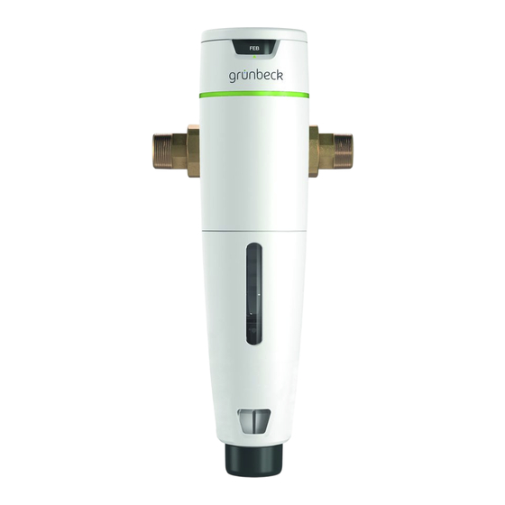
Product description 3.2 Product components Designation Designation Water meter screw Automatic unit with controller connection LEDs for backwash intervals Seal Push-button Pressure reducer handwheel Inspection window Maintenance ring with month indicator Adapter for drain connection Click-type connection flange Plug-in power supply unit with mains cable Pressure gauge 14 | 60... -
Page 15: Functional Description
Product description 3.3 Functional description The unfiltered drinking water flows into the filter through the inlet side and from the outside in through the filter element and to the pure water outlet. Thus, foreign particles of a size > 100 µm are re- tained. -
Page 16: Accessories
Product description 3.4 Accessories You can retrofit your product with accessories. Please contact your local Grünbeck representative or Grünbeck’s headquarters in Hoechstaedt/Germany for details. Illustration Product Order no. Drain connection DN 50 188 875 For professional installation according to DIN EN 1717 with integrated siphon to discharge the backwash water to the drain. -
Page 17: Transport And Storage
Transport and storage Transport and storage 4.1 Transport ► Transport the product in its original packaging only. 4.2 Storage ► Protect the product from the impacts below when storing it: • Dampness, moisture • Environmental impacts such as wind, rain, snow, etc. •... -
Page 18: Installation
Installation Installation The installation of the product represents a major intervention into the drinking water system and must be carried out by a qualified specialist only. In accordance with DIN EN 806-2 and DIN EN 1717, the product is installed in the cold water pipe downstream of the water meter and upstream of distribution pipes and the appliances to be protected. - Page 19 Installation Installation example in vertical pipe Designation Designation Piping to be provided by the cli- Safety device protectliQ ent on site for drain connection Inlet shut-off valve DN 50 acc. to DIN EN 1717 Outlet shut-off valve 19 | 60...
-
Page 20: Requirements For The Installation Site
Installation 5.1 Requirements for the installation site ● The installation site must be frost-proof and ensure the filter's protection from chemicals, dyes, solvents and their vapours as well as from direct sunlight. ● The installation site must be away from heat sources (e.g. washing machines, boilers and hot water pipes). -
Page 21: Checking The Scope Of Supply
Installation 5.2 Checking the scope of supply Designation Designation Water meter screw Plug-in power supply unit with connection mains cable of approx. 1.5 m in length Seal Quick reference manual Automatic filter pureliQ:A or pureliQ:AD ► Check the scope of supply for completeness and damage. The transparent plastic film serves as transport and dirt protection. -
Page 22: Water Installation
Installation 5.3 Water installation The rotatable click-type connection flange allows the filter to be adapted to any flow direction given on site. The filter can be installed in a horizontal or vertical water pipe. 5.3.1 Preparing the pipe ► Install the water meter screw connection in the pipe. »... - Page 23 Installation 3. Rotate the click-type connection flange into the position matching your flow direction (refer to the marking on the click- type connection flange). » The arrow must correspond to the flow direction of the water. 4. Remove the protective caps. 5.
- Page 24 Installation » The filter is installed. 24 | 60...
- Page 25 Installation 5.3.3 Attaching the backwash connection Discharge of backwash water with drain connection Designation Designation Drain connection DN 50 acc. Waste water pipe provided by to DIN EN 1717 client on site Refer to the mounting instructions of the drain connection (order no.
-
Page 26: Start-Up/Commissioning
Start-up/Commissioning Start-up/Commissioning The initial start-up/commissioning of the product must be carried out by technical service personnel only. 6.1 Checking the product 1. Open the shut-off valves. 2. Open the closest water withdrawal point downstream of the filter to the maximum. 3. -
Page 27: Setting The Month Indicator
Start-up/Commissioning The filter does not automatically backwash during initial start-up/ commissioning. A backwash interval of 60 days is factory-set. 5. Start a manual backwash (refer to chapter 7.2.2). The interval counter is then set to zero. The next backwash takes place at the set interval. -
Page 28: Setting The Pressure Reducer (Pureliq:ad)
Start-up/Commissioning 6.3 Setting the pressure reducer (pureliQ:AD) The factory setting for the pressure reducer is 4 bar. You can change this value as follows: 1. Set the required outlet pressure on the pressure reducer handwheel (turn counterclockwise = pressure increase, turn clockwise = pressure reduction). -
Page 29: Handing Over The Product To The Owner/ Operating Company
Start-up/Commissioning 6.4 Handing over the product to the owner/ operating company ► Explain to the owner/operating company how the product works. ► Use the manual to brief the owner/operating company and answer any questions. ► Inform the owner/operating company about the need for in- spections and maintenance. -
Page 30: Operation
Operation Operation The filter is operated automatically and does not require any manual operation. The motor unit of the filter takes over the backwash independently and time-controlled. The filter should always be connected to the power supply. If the power supply is interrupted, the filter automatically completes any backwash that might be in progress. -
Page 31: Operating The Backwash Unit
Operation 7.2 Operating the backwash unit The automatic filter automatically starts backwash processes at the set intervals. The backwash intervals are factory-set to 60 days. You can change the backwash intervals. 7.2.1 Setting the backwash intervals ► Press the push-button repeatedly until the desired backwash interval is set. - Page 32 Operation » The backwash process takes about 50 seconds. ► In case some particles still remain on the filter element, start a manual backwash again. 7.2.2 Starting a manual backwash ► Press the push-button for 3 seconds. » During the backwash process, approx. 14 l of backwash water are discharged to the drain.
-
Page 33: Maintenance And Repair
Maintenance and repair Maintenance and repair Maintenance and repair includes cleaning, inspection and mainte- nance of the product. The responsibility for inspection and maintenance is subject to local and national requirements. The owner/operating company is re- sponsible for compliance with the prescribed maintenance and re- pair work. -
Page 34: Intervals
Maintenance and repair 8.2 Intervals By way of regular inspections and maintenance, malfunctions can be detected in time and product failures might be prevented. ► As owner/operating company determine which components must be inspected and maintained at which intervals (load- dependent). -
Page 35: Inspection
Maintenance and repair 8.3 Inspection You as owner/operating company can carry out the regular inspec- tions yourself. ► Carry out an inspection at least every 2 months and proceed as follows to do so: 1. Check the installation for leaks and function. 2. -
Page 36: Maintenance
Maintenance and repair 8.4 Maintenance For safety reasons, Grünbeck recommends semi-annual mainte- nance and annual maintenance according to DIN EN 806-5 in order to ensure trouble-free and hygienic operation of the product. 8.4.1 Semi-annual inspection 1. Check the installation for leaks and function. 2. - Page 37 Maintenance and repair ► Close the shut-off valves on the inlet and on the outlet. 1. Carry out a manual backwash to relieve the water pressure in the filter and in the water pipe. 2. Pull the plug-in power supply unit from the socket. 3.
- Page 38 Maintenance and repair Designation Designation Control unit Motor unit Mains cable with power sup- Microswitch ply unit 5. Pull the control unit from the cover of the filter cylinder. Make sure not to damage the mains cable. 6. Disconnect the connector of the motor unit and the micro- switch from the circuit board.
- Page 39 Maintenance and repair 8. Loosen the fastening nut. Firmly hold the motor unit with the microswitch while doing so. 9. Carefully pull off the cover of the filter cylinder. 10. Check the motor unit for wear and tear. 39 | 60...
- Page 40 Maintenance and repair 11. Replace the motor unit, if necessary. You can remove the filter cylinder together with the motor unit. Designation Designation O-ring of filter cylinder Filter element Filter cylinder Backwash valve incl. seal 12. Unscrew the filter cylinder. Make sure not to damage the mo- tor unit with the microswitch.
-
Page 41: Spare Parts
Maintenance and repair 16. Replace worn components as needed (refer to chapter 8.6). ► Install the filter and put the installation back into operation again (refer to chapter 6). 8.5 Spare parts For an overview of the spare parts, refer to our spare parts cata- logue at www.gruenbeck.com. -
Page 42: Service Kits
Maintenance and repair 8.7 Service kits 8.7.1 Service kits for pureliQ:A Designation Designation Filter element Backwash valve incl. seals O-ring of filter cylinder Fastening nut incl. seal Filter cylinder Automatic drive Designation Consisting of: Order no. Recommended re- placement interval •... - Page 43 Maintenance and repair 8.7.2 Service kits for pureliQ:AD Designation Designation Filter element Fastening nut incl. seal O-ring of filter cylinder Automatic drive Filter cylinder Pressure reducer Backwash valve incl. seals Pressure gauge Recommended re- Designation Consisting of: Order no. placement interval •...
- Page 44 Maintenance and repair Tools required Order no. 105 805 Strap wrench (to remove the filter cylinder) 104 805 Pipe socket wrench (for pressure reducer cartridge) Allen key 10 (for fastening nut) TORX T8 (pressure gauge) TORX T10 (pressure reducer adjusting cap) 44 | 60...
-
Page 45: Troubleshooting
Troubleshooting Troubleshooting Contaminated drinking water due to stagnation WARNING ● Infectious diseases ► Have malfunctions eliminated immediately. 9.1 Messages LED message Explanation Remedy All four LEDs are flashing • Timeout during the backwash procedure (> 115 s) • Timeout when starting the backwash ►... -
Page 46: Observations
Troubleshooting 9.2 Observations Observation Explanation Remedy ► Fully open the shut-off Water pressure at the The shut-off valves are withdrawal point too not fully open valves low (pressure loss too ► Carry out manual back- The filter element is dirty high) wash ►... -
Page 47: Decommissioning
Decommissioning 10 Decommissioning It is not necessary to put your product out of operation. In case of longer absences, e.g. holidays, precautionary hygiene measures according to VDI 3810-2 and VDI 6023-2 must be taken in order to maintain drinking water hygiene after downtimes. 10.1 Temporary downtime Should you wish to temporarily shut down your water supply due to a longer period of absence, proceed as follows. -
Page 48: Dismantling And Disposal
Dismantling and disposal 11 Dismantling and disposal 11.1 Dismantling The work described herein represents an intervention into your drinking water system. ► Have this work carried out by qualified specialists only. 1. Close the shut-off valves upstream and downstream of the fil- ter. -
Page 49: Disposal
Dismantling and disposal 11.2 Disposal ► Obey the applicable national regulations. Packaging Danger to the environment due to incorrect dis- NOTE posal ● Packaging materials are valuable raw materials that can be reused in many cases. ● Incorrect disposal can cause hazards to the environment. ►... - Page 50 Dismantling and disposal Product If this symbol (crossed-out wheelie bin) is on the product, this product or its electrical and electronic components must not be disposed of as household waste. ► Find out about the local regulations on the separate collec- tion of electrical and electronic products.
-
Page 51: Technical Specifications
Technical specifications 12 Technical specifications 12.1 pureliQ:A Dimensions and weights pureliQ:A Nominal connection diameter DN 20 DN 25 DN 32 Connection diameter ¾" 1" 1¼" Drain connection DN 50 Installation height up to centre of connection Installation length with/without 185/100 182/100 191/100 screw connection... - Page 52 Technical specifications Connection data 100 – 240/50 – 60 Power supply V/Hz Power input 2/0.075 Operation = max./standby Protection/protection class IP42/ Performance data Nominal flow at p 0.2 (0.5) bar m³/h 3.2 (5.1) 4.2 (6.7) 5.0 (8.0) value m³/h 11.3 Pore size µm Largest/smallest pore size...
-
Page 53: Pressure Loss Curves Of Pureliq:a
Technical specifications 12.2 Pressure loss curves of pureliQ:A Designation Designation Pressure loss in bar Flow rate in m 53 | 60... -
Page 54: Pureliq:ad
Technical specifications 12.3 pureliQ:AD Dimensions and weights pureliQ:AD AD20 AD25 AD32 Nominal connection diameter DN 20 DN 25 DN 32 Connection diameter ¾" 1" 1¼" Drain connection DN 50 Installation height up to centre of connection Installation length with/without 185/100 182/100 191/100 screw connection... - Page 55 Technical specifications Connection data AD20 AD25 AD32 100 – 240/50 – 60 Power supply V/Hz Power input 2/0.075 Operation = max./standby Protection/protection class IP42/ Performance data AD20 AD25 AD32 Flow rate as per DIN EN 1567 m³/h Pore size µm Largest/smallest pore size µm 120/80...
-
Page 56: Operation Log
Operation log 13 Operation log ► Document the initial start-up/commissioning and all mainte- nance activities. Automatic filter pureliQ: ________ Serial no.: ____________________ 13.1 Start-up/Commissioning log Customer Name Address Installation/Accessories Drain connection in accordance with DIN EN 1717 Floor drain present Safety device Operating values Water pressure at raw water inlet... -
Page 57: Maintenance
Operation log 13.2 Maintenance Date Work performed Signature 57 | 60... - Page 58 EU Declaration of Conformity EU Declaration of Conformity In accordance with the EU Low-Voltage Directive 2014/35/EU, Appendix IV This is to certify that the system designated below meets the safety and health pro- tection requirements of the applicable EU guidelines in terms of its design, construc- tion and execution.
- Page 60 Grünbeck Wasseraufbereitung GmbH Josef-Grünbeck-Str. 1 89420 Hoechstaedt/Germany +49 9074 41-0 +49 9074 41-100 info@gruenbeck.com For more information go to www.gruenbeck.com www.gruenbeck.com...
Need help?
Do you have a question about the pureliQ:A20 and is the answer not in the manual?
Questions and answers