Table of Contents
Advertisement
Quick Links
Advertisement
Table of Contents

Subscribe to Our Youtube Channel
Related Manuals for Tews Technologies TAMC532


Summary of Contents for Tews Technologies TAMC532
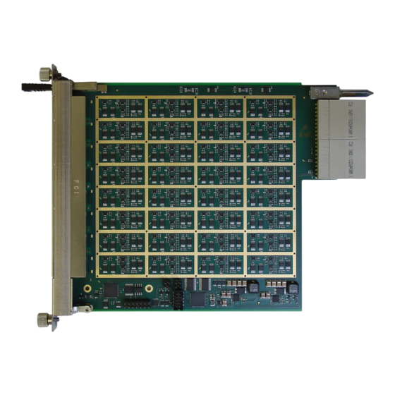
- Page 1 32 x 12/14 Bit 50/75 Msps ADC for MTCA.4 Rear-I/O Version 1.1 User Manual Issue 1.1.0 September 2021 TEWS TECHNOLOGIES GmbH Am Bahnhof 7 25469 Halstenbek, Germany Phone: +49 (0) 4101 4058 0 Fax: +49 (0) 4101 4058 19 e-mail: info@tews.com...
- Page 2 However TEWS TECHNOLOGIES GmbH reserves the right to change the product described in this document at any time without notice. TEWS TECHNOLOGIES GmbH is not liable for any damage arising out of the application or use of the device described herein.
- Page 3 Updated LMK Setup Interface Control Register Added CPS Setup Interface Control Register FPGA: ADC SIPO Unit Disable added to the Module Control Register ADC Loss Of Calibration Detected added to the Module Status Register TAMC532 User Manual Issue 1.1.0 Page 3 of 95...
- Page 4 All phrases related to the user-programmability of the FPGA are removed throughout the document. This better matches the fact that the TAMC532 is delivered with a factory programmed firmware. Description of LEDs 1-4 revised and User Mode added Jitter Attenuator Control Register removed from BCC, as the jitter attenuator has been removed.
-
Page 5: Table Of Contents
Input Voltage Range ....................... 30 Debug ............................. 31 5.10.1 LEDs ............................31 5.10.2 UART ............................31 5.10.3 JTAG ............................31 Reset .............................. 31 μRTM Detection ..........................31 ADDRESSABLE RESOURCES .................. 32 FPGA .............................. 32 TAMC532 User Manual Issue 1.1.0 Page 5 of 95... - Page 6 LMK Write Data Register [x] ....................78 6.2.2.12 CPS Setup Interface Control Register (0x20) ..............79 6.2.2.13 CPS Setup Interface Status Register (0x21) ..............79 6.2.2.14 CPS Setup Interface Read Data (0x22) ................80 TAMC532 User Manual Issue 1.1.0 Page 6 of 95...
- Page 7 Zone 3 Connectors........................90 10.2.1 J30 ............................90 10.2.2 J31 ............................90 SFP+ Connectors .......................... 91 FPGA JTAG Connector ........................ 92 Debug Connector .......................... 93 AMC Connector ..........................94 MMC Header ..........................95 TAMC532 User Manual Issue 1.1.0 Page 7 of 95...
- Page 8 TABLE 6-28 : DMA DESCRIPTOR DATA MEMORY ADDRESS ..............61 TABLE 6-29 : RESERVED ..........................61 TABLE 6-30 : BCC TARGET REGISTER SPACE ..................62 TABLE 6-31 : LMK04816 STATUS REGISTER (0X00) ................. 63 TAMC532 User Manual Issue 1.1.0 Page 8 of 95...
- Page 9 TABLE 10-4 : FPGA JTAG CONNECTOR PIN ASSIGNMENT ..............92 TABLE 10-5 : DEBUG CONNECTOR PIN ASSIGNMENT ................93 TABLE 10-6: AMC CONNECTOR PIN ASSIGNMENT ................... 94 TABLE 10-7 : MMC HEADER PIN ASSIGNMENT, FACTORY USE ONLY ........... 95 TAMC532 User Manual Issue 1.1.0 Page 9 of 95...
- Page 10 FIGURE 5-7 : SINGLE ANALOG INPUT ......................29 FIGURE 5-8 : 8 X ANALOG INPUT GROUP ....................30 FIGURE 6-1 : TAMC532 FIRMWARE SOC STRUCTURE ................32 FIGURE 7-1 : BOARD CONFIGURATION OVERVIEW ................. 82 FIGURE 8-1 : HOT-SWAP STATES ....................... 84 FIGURE 9-1 : FRONT PANEL LED VIEW ......................
-
Page 11: Product Description
12 Bit resolution (optional 50 Msps at 14 Bit). The TAMC532 utilizes Back-IO via Zone 3 to interface the ADCs with the signal conditioning located on the μRTM. This modular concept allows adapting the TAMC532 to nearly any analog input requirement without changing the AMC itself. -
Page 12: Technical Specification
FPGA XC7K70T-1FBG676C or compatible DDR3 Memory MT41J64M16LA or compatible Flash N25Q256 or compatible TAMC532-10R : AD9637 (12 Bit resolution) TAMC532-11R : AD9257 (14 Bit resolution) Zone 3 I/O Interface Analog Input Voltage 0V ±1V (differential) Number of Channels I/O Connector 2 x 30pair ADF Connector according to MTCA.4... -
Page 13: Handling And Operating Instructions
The FPGA I/O-Lines to the μRTM are directly connected to the FPGA I/O pins. The I/O voltage of these FPGA I/O pins is 2.5V maximum. The FPGA I/O pins are NOT 3.3V or 5V tolerant. TAMC532 User Manual Issue 1.1.0 Page 13 of 95... -
Page 14: Ipmi Support
Chassis Info Area Board Info Area variable Product Info Area variable Multi Record Area Module Current Requirements variable AMC Point-to-Point Connectivity variable Clock Configuration variable Compatibility Record variable Table 4-2 : FRU Information TAMC532 User Manual Issue 1.1.0 Page 14 of 95... -
Page 15: Board Info Area
The AMC’s MMC announces the current demand to the shelf manager. If the power budget for the AMC slot is smaller than this value, the shelf manager may not enable Payload power for the used slot. TAMC532 User Manual Issue 1.1.0 Page 15 of 95... -
Page 16: Amc Point-To-Point Connectivity
Gen 2 PCI Express, Single Channel Link Express non-SSC Primary Port PCI Express AMC.1 PCI Gen 2 PCI Express, Single Channel Link Express Primary Port Table 4-6 : AMC Point-to-Point Connectivity TAMC532 User Manual Issue 1.1.0 Page 16 of 95... -
Page 17: Clock Configuration
Table 4-7 : Clock Configuration 4.2.4 Modifying FRU Records Some of the records are writeable to allow adaption to certain systems. If records are modified, the user is responsible for setting the proper checksums. TAMC532 User Manual Issue 1.1.0 Page 17 of 95... -
Page 18: Functional Description
Figure 5-1 : Functional Block Diagram FPGA The heart of the TAMC532 is the Kintex-7 FPGA. It is configured with a firmware that provides a very functional readout system and control over the numerous clocking and trigger options. 5.2.1 Interrupt Handling The firmware contains different functions or sub-components. -
Page 19: Dma Controller
(Descriptor Queue Size is 0xFF). The loaded Descriptor information is queued after the last Descriptor stored within the internal buffer. TAMC532 User Manual Issue 1.1.0 Page 19 of 95... -
Page 20: Adc Data Acquisition
Note that the CSPT configuration should be defined (via writes into the defined registers) before any unit is enabled. In accordance with that, before changing the configuration, all units have to be disabled. The CSPT unit applies a static data source mode (CSPT_DSM) and data acquisition mode (CSPT_DAM). TAMC532 User Manual Issue 1.1.0 Page 20 of 95... -
Page 21: Table 5-1 : Maximum Sample Count Per Channel
Caused by the automatic DMA Buffer termination (CSPT_ABT), all pending data is flushed from the DMA Controller Buffer and the current active DMA Buffer (Descriptor) is terminated, including signaling the selected interrupts. TAMC532 User Manual Issue 1.1.0 Page 21 of 95... -
Page 22: Table 5-2 : Adc Data Alignment
(CSPT Unit Software Trigger Input). The external input can be disabled while the software input is always available. Note that the external trigger input is subdued an edge evaluation and level mode is not supported. TAMC532 User Manual Issue 1.1.0 Page 22 of 95... -
Page 23: I2C Bridge
(WRS_SRD_DCNT) is not 0x00. It is expected that the slave acknowledges every write cycle (ACK). If the slave signals a not acknowledge (NACK), the I2C operation is aborted and an error is reported (DEV_OP_ERR). TAMC532 User Manual Issue 1.1.0 Page 23 of 95... -
Page 24: Board Configuration Controller (Bcc)
(MST_IDLE). In accordance to that, the fault of a loss of arbitration (BUS_ARBL) and/or erroneous operation (DEV_OP_ERR), will also result in an interrupt generation. Board Configuration Controller (BCC) The TAMC532 provides a board configuration controller (BCC) to support the following tasks: Power sequencing Level shifting for various signals... -
Page 25: Ddr3 Memory
Memory Kintex-7 Figure 5-2 : DDR3 Memory Interfaces Fabric Interfaces The TAMC532 provides the following fabric interfaces: x4 Multi-Gigabit Link between FPGA and AMC Fat Pipe Region (e.g. AMC port 4-7) Kintex-7 AMC Port 4-7 Figure 5-3 : Fabric Interfaces 5.5.1 PCI-Express... -
Page 26: Flash Memory
The TAMC532 provides SPI flash devices that are used to store the FPGA firmware. After power-up, the FPGA automatically loads its firmware. ADC Clocking From a top level view, the ADC clocking structure of the TAMC532 provides 4 clock inputs and 9 clock outputs. BCC_I2C Prog. -
Page 27: Crosspoint Switch
Due to the nature of the dual PLL structure, the input frequency has a low limit of 10kHz. To support any input frequency above 10kHz, the first PLL makes use of an in-system programmable VCXO. See chapter “Mandatory Devices” for the exact device type. TAMC532 User Manual Issue 1.1.0 Page 27 of 95... -
Page 28: Vcxo
Any of the four crosspoint switch inputs can be connected to AMC_CLK0. By default, the output buffer of AMC_CLK0 is disabled. Only if ZONE3_EN is high, the User can enable the buffer by setting the DIP Switch accordingly. If ZONE3_EN is going low the buffer is immediately disabled. TAMC532 User Manual Issue 1.1.0 Page 28 of 95... -
Page 29: Trigger And Gpio
Trigger and GPIO The TAMC532 provides access to several GPIO signals at the AMC Connector and the Zone 3 Interface. Each of these signals can be used as a trigger input. Direction & Fail-Save setting (8x) Level M-LVDS AMC Port... -
Page 30: Adc Sample Clock
Four Octal ADCs are used on the TAMC532, each combining eight ADCs into a single chip. As a result, only one data clock and one frame clock signal is needed to sample the serial data streams of 8 ADCs into the FPGA. -
Page 31: Debug
The TAMC532 provides a UART on the Debug Connector. The UART is used by the MMC and provides IPMI related debug information at 38400 baud. 5.10.3 JTAG The TAMC532 provides 4 different ways to gain access over the JTAG-Chain the Kintex-7 is part of. It can be accessed by: (1) The Module Management Controller (MMC) -
Page 32: Addressable Resources
Another register subset is mapped into the application function unit. Three separate bridge interfaces are included to allow accessing the different I2C busses on the TAMC532 (BCC, Payload and RTM). Every bridge interface owns an independent register set to stimulate the connect I2C master. -
Page 33: Pcie Configuration
Subsystem ID xx value encodes the module variant in a hexadecimal representation (TEWS definition). Port Size Endian Space Prefetch Width Description (Byte) Mode (Bit) Module Register Space Table 6-2 : PCIe Bar Overview TAMC532 User Manual Issue 1.1.0 Page 33 of 95... -
Page 34: Register Interface
DMA Controller #0 Base Descriptor Address Register 0x8C DMA Controller #0 Current Memory Write Address Register 0x90 DMA Controller #1 Control Register 0x94 DMA Controller #1 Status Register 0x98 DMA Controller #1 Base Descriptor Address Register TAMC532 User Manual Issue 1.1.0 Page 34 of 95... - Page 35 CSPT Unit D Data Register #0 – Pre-Trigger Value (Application Control Register #11) 0x13C CSPT Unit D Data Register #1 – Post-Trigger Value (Application Control Register #12) 0x140 Reserved 0x144 : 0x15F Reserved TAMC532 User Manual Issue 1.1.0 Page 35 of 95...
-
Page 36: Module Control Register (0X00)
If it is not set, the information within the Module Status Register are inhibited from generating PCIe MOD_INT_GE Interrupts. Bit information mean: 0b0 = enable PCIe Interrupts 0b1 = disable PCIe Interrupts Table 6-4 : Module Control Register (0x00) TAMC532 User Manual Issue 1.1.0 Page 36 of 95... -
Page 37: Module Status Register (0X04)
0b1 = Calibration completed Module Interrupt Mode MSI Indicates that the module uses MSI interrupts for interrupt generation. MOD_INT_MODE_MSI Bit information mean: 0b0 = MSI are not used 0b1 = MSI are used TAMC532 User Manual Issue 1.1.0 Page 37 of 95... -
Page 38: Table 6-5 : Module Status Register (0X04)
MOD_INT_MODE_ERR 0b0 = Interrupts configured correctly (INTA/MSI) 0b1 = Interrupts configuration erroneous No interrupts will be generated in case of an invalid interrupt configuration Table 6-5 : Module Status Register (0x04) TAMC532 User Manual Issue 1.1.0 Page 38 of 95... -
Page 39: Module Interrupt Enable Register (0X08)
0b1 = enable interrupt generation DMA Controller #2 Descriptor Data Memory Filled Interrupt Enable DMAC_DMF_2_EN Controls whether an interrupt is generated after a descriptor has been processed / finalized that has the HI_DMF bit set. TAMC532 User Manual Issue 1.1.0 Page 39 of 95... - Page 40 0b1 = enable interrupt generation Reserved DMA Controller #0 Descriptor End-Of-List Enable Controls whether an interrupt is generated after a DMAC_EOL_0_EN descriptor has been processed / finalized that has the HI_EOL bit set. TAMC532 User Manual Issue 1.1.0 Page 40 of 95...
-
Page 41: Table 6-6 : Module Interrupt Enable Register (0X08)
Enable/disable signalisation of BCC interrupt information. BCC_INTR_EN Bit setting means: 0b0 = disable interrupt generation 0b1 = enable interrupt generation Reserved 1 : 0 0b00 Table 6-6 : Module Interrupt Enable Register (0x08) TAMC532 User Manual Issue 1.1.0 Page 41 of 95... -
Page 42: Module Interrupt Status Register (0X0C)
0b1 = HI_DMF bit signalisation DMA Controller #2 Descriptor Data Loaded A descriptor has been loaded and queued, which has the HI_DDL bit set. DMAC_DDL_2 R/W1C Bit information mean: 0b0 = default TAMC532 User Manual Issue 1.1.0 Page 42 of 95... - Page 43 DMA Controller #0 Descriptor Data Loaded A descriptor has been loaded and queued, which has the HI_DDL bit set. DMAC_DDL_0 R/W1C Bit information mean: 0b0 = default 0b1 = HI_DDL bit signalisation TAMC532 User Manual Issue 1.1.0 Page 43 of 95...
-
Page 44: Adc Channel [Xx] Data Register
Table 6-8 : ADC Channel [xx] Data Register The reset value is shown before the ADC input calibration has been successfully performed. The ADC Channel Data is always the last valid input obtained during successful ADC input calibration. TAMC532 User Manual Issue 1.1.0 Page 44 of 95... -
Page 45: I2C Bridge Control Register (0X50)
11 : 4 0x00 WRS_SRD_DCNT 0x01 = 1 Byte … 0xFF = 255 Bytes If 0x00 is selected, no read operation will be performed Reserved 3 : 1 0b000 I2C Bridge Enable I2C_BRDG_EN TAMC532 User Manual Issue 1.1.0 Page 45 of 95... -
Page 46: I2C Bridge Clock Divider Register (0X54)
Read Data FIFO Current Fill Level Reports the number of read data bytes currently 23 : 16 0x00 RD_DFIFO_CFL available for reading from the Read Data FIFO. Bit information means: TAMC532 User Manual Issue 1.1.0 Page 46 of 95... - Page 47 I2C master. WRS_OP_IP Bit information means: 0b0 = No transfer in progress 0b1 = Transfer in progress Information is signaled until the end of the transfer TAMC532 User Manual Issue 1.1.0 Page 47 of 95...
-
Page 48: I2C Bridge Command Register (0X5C)
RD_DFIFO_RST R0/W1 zero. Self-clearing command bit (reset by hardware) Write Data FIFO Reset WR_DFIFO_RST R0/W1 W1 writing clears the write data FIFO and resets its current fill level counter (WR_DFIFO_CFL) to TAMC532 User Manual Issue 1.1.0 Page 48 of 95... -
Page 49: I2C Bridge Write Data Fifo Interface Register (0X60)
FIFO. 31 : 0 0x00000000 RD_DFIFO_DREG Every read will decrement its current fill level counter (RD_DFIFO_CFL) Table 6-14 : I2C Bridge Read FIFO Data Register (0x64) TAMC532 User Manual Issue 1.1.0 Page 49 of 95... -
Page 50: Dma Controller [X] Control Register
Descriptor that can be loaded Descriptor Controller Handler Erroneous Completion Received DMAC_DQH_ECR Error condition: Descriptor data read failed. An error occurred while attempting to read TAMC532 User Manual Issue 1.1.0 Page 50 of 95... -
Page 51: Dma Controller [X] Base Descriptor Address Register
Register writes cause a descriptor load 31:0 0x00000000 DMAC_BDA sequence (stored / queued operation) if the descriptor memory is not full (not equal to 0xFF) Table 6-17 : DMA Controller [x] Base Descriptor Address Register TAMC532 User Manual Issue 1.1.0 Page 51 of 95... -
Page 52: Dma Controller [X] Current Memory Write Address Register
Shows the host memory address within the 31:0 0x00000000 DMAC_CMWRA currently active descriptor pointed host memory window, used for the next memory write Table 6-18 : DMA Controller [x] Current Descriptor Address Register TAMC532 User Manual Issue 1.1.0 Page 52 of 95... -
Page 53: Application Control Register (0X100)
Internal CSPT Unit memory interface synchronization requires that the CSPT Units that share an memory interface (A and B or C and D) are both disabled before enabling either of them or both. TAMC532 User Manual Issue 1.1.0 Page 53 of 95... -
Page 54: Cspt Unit [X] Control Register
RTM D3 and RTM D4 (both differential) have been removed for compliance with TEWS RTM External trigger inputs are edge evaluated and level mode is not supported. 7 : 5 Reserved TAMC532 User Manual Issue 1.1.0 Page 54 of 95... -
Page 55: Table 6-20 : Cspt Unit [X] Control Register
Disabling the automatic buffer termination requires manual flushing (CSPT_SW_BTERM) if the acquired amount of data does not match the buffer size. 3 : 0 Reserved Table 6-20 : CSPT Unit [x] Control Register TAMC532 User Manual Issue 1.1.0 Page 55 of 95... -
Page 56: Cspt Unit [X] Data Register #0 - Pre-Trigger Sample Count
Trigger detected while CSPT Unit was not idle (missed trigger) 15 : 12 CSPT_ERR Bit information mean: 0b0 = CSPT Unit is functional 0b1 = CSPT Unit signals error condition Cleared when corresponding CSPT Unit is disabled TAMC532 User Manual Issue 1.1.0 Page 56 of 95... -
Page 57: Table 6-23 : Application Status Register (0X160)
CSPT-Unit: Bit #3 corresponds with CSPT Unit D Bit #2 corresponds with CSPT Unit C Bit #1 corresponds with CSPT Unit B Bit #0 corresponds with CSPT Unit A TAMC532 User Manual Issue 1.1.0 Page 57 of 95... -
Page 58: Application Command Register (0X164)
CSPT-Unit: Bit #3 corresponds with CSPT Unit D Bit #2 corresponds with CSPT Unit C Bit #1 corresponds with CSPT Unit B Bit #0 corresponds with CSPT Unit A TAMC532 User Manual Issue 1.1.0 Page 58 of 95... -
Page 59: Firmware Identification Register (0X1Fc)
FW_MAJ_VER Firmware Minor Version 23 : 16 0x00 FW_MIN_VER Firmware Revision 15 : 8 FW_REV 0x00 Firmware Build Count 7 : 0 0x00 FV_BLD_CNT Table 6-25 : Firmware Identification Register (0x1FC) TAMC532 User Manual Issue 1.1.0 Page 59 of 95... -
Page 60: Dma Descriptor Control Dw
/ finalized (loading respectively switching to its successor). Bit setting means: DESCR_HI_DMF 0b1 = enable interrupt generation 0b0 = disable interrupt generation The interrupt is issued concurrently to the data submission TAMC532 User Manual Issue 1.1.0 Page 60 of 95... -
Page 61: Dma Descriptor Next Descriptor Address
The address and boundary must be DW aligned Table 6-28 : DMA Descriptor Data Memory Address 6.1.4.4 Reserved Reset Symbol Description Access Value 31 : 0 Reserved 0x00000000 Table 6-29 : Reserved TAMC532 User Manual Issue 1.1.0 Page 61 of 95... -
Page 62: Board Configuration Controller (Bcc)
Reserved 0xFC Firmware Identification Register (Major ID) 0xFD Firmware Identification Register (Minor ID) 0xFE Firmware Identification Register (Revision) 0xFF Firmware Identification Register (Build Count) Table 6-30 : BCC Target Register Space TAMC532 User Manual Issue 1.1.0 Page 62 of 95... -
Page 63: Lmk04816 Status Register (0X00)
0b0 = Signal input detected For a deterministic ADC operation clock input #1 should signal an input, bit #0/#2 are irrespective (under default configuration) Table 6-31 : LMK04816 Status Register (0x00) TAMC532 User Manual Issue 1.1.0 Page 63 of 95... -
Page 64: Si5338 Status Register (0X01)
Bit information mean: UCG_INTR 0b0 = Interrupt request not asserted 0b1 = Interrupt request asserted Under normal conditions no interrupt request should be asserted Table 6-32 : SI5338 Status Register (0x01) TAMC532 User Manual Issue 1.1.0 Page 64 of 95... -
Page 65: Amc Rx/Tx Differential Pair [X] Control Register
0b0 = Disable RX Differential Output 0b1 = Enable RX Differential Output MLVDS device resist multiple drivers on the same node Table 6-33 : AMC Rx/Tx Differential Pair [x] Control Register TAMC532 User Manual Issue 1.1.0 Page 65 of 95... -
Page 66: Sfp Control Register (0X06)
TX Disable SFP #0 Affects the SPF #0 TX output disable pin. SFP0_TX_DIS 0b0 = Pin set to low-level 0b1 = Pin set to high-level Table 6-34 : SFP Control Register (0x06) TAMC532 User Manual Issue 1.1.0 Page 66 of 95... -
Page 67: Spi Control Register (0X07)
0b00 = Selection is based on FPGA RS Pins 0b01 = Static SPI #0 Selection 0b10 = Static SPI #1 Selection 0b11 = Both SPI Flashes are disconnected Table 6-35 : SPI Control Register (0x07) TAMC532 User Manual Issue 1.1.0 Page 67 of 95... -
Page 68: Miscellaneous Register (0X09)
Enables or disables the FPGA configuration I2C bus access. Bit setting means: CONFIG_I2C_EN 0b0 = disabled 0b1 = enabled FPGA is decoupled by default to allow BCC I2C configuration after power-up Table 6-36 : Miscellaneous Register (0x09) TAMC532 User Manual Issue 1.1.0 Page 68 of 95... -
Page 69: Configuration Dip Switches Register (0X0A)
OP Amplifier ADC C1 Disable Bit Adjusts whether the analogue Operation Amplifier s for ADC C1 are disabled or enabled. DIS_AMP_C1 Affected analog input paths: [ 16 22 ] Bit setting means: 0b0 = enabled TAMC532 User Manual Issue 1.1.0 Page 69 of 95... - Page 70 OP Amplifier ADC A Disable Bit Adjusts whether the analogue Operation Amplifier s for ADC A are disabled or enabled. DIS_AMP_A Affected analog input paths: [ 0 1 2 3 5 6 7 ] TAMC532 User Manual Issue 1.1.0 Page 70 of 95...
-
Page 71: Table 6-39 : Adc Input Amplifiers Control Register (0X0B)
Description Access Value Bit setting means: 0b0 = enabled 0b1 = disabled Setting is only effective if MMC signals a compatible RTM Table 6-38 : ADC Input Amplifiers Control Register (0x0B) TAMC532 User Manual Issue 1.1.0 Page 71 of 95... -
Page 72: Frequency Adjustment Control Register (0X0C)
FW_MIN_VER BCC Firmware Minor Version 0x00 15 : 8 FW_REV BCC Firmware Revision 0x00 7 : 0 FV_BLD_CNT BCC Firmware Build Count 0x00 Table 6-40 : BCC Firmware Identification Register (0xFC) TAMC532 User Manual Issue 1.1.0 Page 72 of 95... -
Page 73: Configuration-I2C
CPS Setup Interface Control Register 0x21 CPS Setup Interface Status Register 0x22 CPS Setup Interface Read Data 0x23 CPS Setup Interface Write Data 0x24 : 0xFF Reserved Table 6-41 : BCC Bridge Register Space TAMC532 User Manual Issue 1.1.0 Page 73 of 95... -
Page 74: Adc Setup Interface Control Register (0X00)
0b01 = write request in progress 0b10 = read request in progress others = reserved These are self-clearing command bits after request is processed Table 6-42 : ADC Setup Interface Control Register (0x00) TAMC532 User Manual Issue 1.1.0 Page 74 of 95... -
Page 75: Adc Setup Interface Status Register (0X01)
The register content defines together with ADC ADC_UADDR 0x00 Setup Interface Lower Target Address Register the accessed ADC register address for reads or writes Table 6-45 : ADC Setup Interface Upper Target Address Register (0x03) TAMC532 User Manual Issue 1.1.0 Page 75 of 95... -
Page 76: Adc Setup Interface Read Data (0X04)
0b01 = write request in progress 0b10 = read request in progress others = reserved These are self-clearing command bits after request is processed Table 6-48 : LMK Setup Interface Control Register (0x10) TAMC532 User Manual Issue 1.1.0 Page 76 of 95... -
Page 77: Lmk Setup Interface Status Register (0X11)
#3 = 0x00 The read data is separated on the different registers as follows: Register #0, Bits [ 7: 0] Register #1, Bits [15: 8] Register #2, Bits [23:16] Register #3, Bits [31:24] TAMC532 User Manual Issue 1.1.0 Page 77 of 95... -
Page 78: Lmk Write Data Register [X]
Register #0, Bits [ 7: 0] Register #1, Bits [15: 8] Register #2, Bits [23:16] Register #3, Bits [31:24] Bits [4:0] carry the register-address information. Refer to the LMK-manual for more details. TAMC532 User Manual Issue 1.1.0 Page 78 of 95... -
Page 79: Cps Setup Interface Control Register (0X20)
Indicates whether the selected CPS Setup Interface is willing/ready to process read/write commands or not. CPS_SIF_RDY Bit information means: 0b0 = Busy 0b1 = Ready Table 6-53 : CPS Setup Interface Read Data (0x21) TAMC532 User Manual Issue 1.1.0 Page 79 of 95... -
Page 80: Cps Setup Interface Read Data (0X22)
Bit information means: 1 : 0 CPS_OP_0_IP 0b00 0b00 = Input #0 0b01 = Input #1 0b10 = Input #2 0b11 = Input #3 Table 6-54 : CPS Setup Interface Read Data (0x22) TAMC532 User Manual Issue 1.1.0 Page 80 of 95... -
Page 81: Cps Setup Interface Write Data (0X23)
Bit information means: 1 : 0 CPS_CIP_IO 0b00 0b00 = Input #0 0b01 = Input #1 0b10 = Input #2 0b11 = Input #3 Table 6-55 : CPS Setup Interface Write Data (0x23) TAMC532 User Manual Issue 1.1.0 Page 81 of 95... -
Page 82: Board Configuration
Table 7-1 : Zone 3 Keying Pin The keying module on the TAMC532 is just for alignment purposes, not for actual keying. This is due to the fact that the voltage levels on the TAMC532 Zone 3 interface do not match with any of the existing key definitions. -
Page 83: Dip-Switch
μRTM is excluded from the AMCs JTAG Chain μRTM is included in the AMCs JTAG Chain (*) Reserved Zone 3 AMC_CLK0 is enabled Zone 3 AMC_CLK0 is disabled (*) Reserved Table 7-2 : DIP-Switch (*) factory default setting TAMC532 User Manual Issue 1.1.0 Page 83 of 95... -
Page 84: Installation
Blue LED starts “Short Blink” (Hot Swap Negotiation in progress) b. Blue LED turns “ON” (Module is ready to be extracted) 2. Pull the module handle out completely and extract the AMC module from the slot. TAMC532 User Manual Issue 1.1.0 Page 84 of 95... -
Page 85: Μrtm Module Installation
3. Wait until the green LED goes off and the blue Hot-Swap LED shows activity 4. Wait until the blue Hot-Swap LED is permanently on 5. Unfasten the μRTM from the MTCA.4 system 6. Pull the μRTM from the MTCA.4 system (handle still pulled) TAMC532 User Manual Issue 1.1.0 Page 85 of 95... -
Page 86: Led Indicators
Power-Supplies are on, Board configuration is in Green Slow blink progress Board is powered up and configured FPGA is not configured or configuration failed FPGA Green FPGA has successfully configured Table 9-2 : Board Status LEDs TAMC532 User Manual Issue 1.1.0 Page 86 of 95... -
Page 87: Table 9-3 : Front Panel Leds 1-4 (Bcc Controlled)
On = ADC Data Channel A, B, C and D calibrated Off = ADC Data Channel A, B, C and D not calibrated The firmware processing functionality (application logic) should only be used if the ADC input stage has been calibrated TAMC532 User Manual Issue 1.1.0 Page 87 of 95... -
Page 88: Table 9-4 : Front Panel Leds 1-4 (Status Mode)
It is possible to change the behavior of LEDs 1-4 by selecting the User Mode in the Application Control Register. In User Mode, the LEDs are under software control. See the Application Control Register description for more details. TAMC532 User Manual Issue 1.1.0 Page 88 of 95... -
Page 89: O Connectors
10 I/O Connectors This chapter provides information about user accessible on-board connectors Overview AMC Connector MMC Header FPGA JTAG Header SFP+ (2x) Debug Connector (Side 2) Figure 10-1 : Connector Overview TAMC532 User Manual Issue 1.1.0 Page 89 of 95... -
Page 90: Zone 3 Connectors
Zone 3 Connectors The TAMC532 provides two 30-pair ADF connectors (J30 and J31) that build the Zone 3 Interface according to Class A2.1. Pin-Count 30 contact pairs (60 signal contacts) + 30 GND pins Connector Type Advanced Differential Fabric (ADF) connector Source &... -
Page 91: Sfp+ Connectors
Receive Data Output+ VeeT Ground VccR Output +3.3 Volt VccT Output +3.3 Volt VeeT Ground Output Transmit Data Input+ Output Transmit Data Input- VeeT Ground Table 10-3 : SFP+ Connector Pin Assignment TAMC532 User Manual Issue 1.1.0 Page 91 of 95... -
Page 92: Fpga Jtag Connector
Test Clock Ground Output Test Data Output Ground Input Test Data Input Ground Not used PGND Input Programmer present detection n.c. Not used Table 10-4 : FPGA JTAG Connector Pin Assignment TAMC532 User Manual Issue 1.1.0 Page 92 of 95... -
Page 93: Debug Connector
Debug Connector The Debug connector is located on Side 2 of the TAMC532, and allows direct connection of the TEWS program and debug box TA900. Pin-Count Connector Type 20-pin, 1mm FPC (Flexible Printed Circuit) Source & Order Info AMP 2-487951-0 / 2-84953-0... -
Page 94: Amc Connector
Connected to CLK0 of FCLKA+ MGT_BANK_116 TCLKB- 165 TCK Differential Clock Input or Output TCLKB+ 166 TMS JTAG Interface TCLKA- 168 TDO Differential Clock Input TCLKA+ 169 TDI Table 10-6: AMC Connector Pin Assignment TAMC532 User Manual Issue 1.1.0 Page 94 of 95... -
Page 95: Mmc Header
Test Data Input (TAP Controller: TDO) Ground Table 10-7 : MMC Header Pin Assignment, factory use only MMC Header is reserved for factory use. Do not plug anything to this header-field. TAMC532 User Manual Issue 1.1.0 Page 95 of 95...
Need help?
Do you have a question about the TAMC532 and is the answer not in the manual?
Questions and answers