Table of Contents
Advertisement
Quick Links
The Embedded I/O Company
TEWS TECHNOLOGIES GmbH
Am Bahnhof 7
25469 Halstenbek, Germany
www.tews.com
Arrow.com.
Downloaded from
TIP866-TM-10
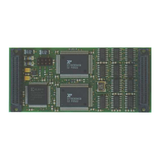
Transition Module for TIP866/TIP867
with 8 DB25 Connectors
User Manual
Phone: +49-(0)4101-4058-0
Fax: +49-(0)4101-4058-19
e-mail: info@tews.com
Version 1.0
Issue 1.5
July 2007
D75866851
TEWS TECHNOLOGIES LLC
9190 Double Diamond Parkway,
Suite 127, Reno, NV 89521, USA
www.tews.com
Phone: +1 (775) 850 5830
Fax: +1 (775) 201 0347
e-mail: usasales@tews.com
Advertisement
Table of Contents

Subscribe to Our Youtube Channel
Summary of Contents for Tews Technologies TIP866-TM-10
- Page 1 Transition Module for TIP866/TIP867 with 8 DB25 Connectors Version 1.0 User Manual Issue 1.5 July 2007 D75866851 TEWS TECHNOLOGIES GmbH TEWS TECHNOLOGIES LLC Am Bahnhof 7 Phone: +49-(0)4101-4058-0 9190 Double Diamond Parkway, Phone: +1 (775) 850 5830 25469 Halstenbek, Germany...
- Page 2 However TEWS TECHNOLOGIES GmbH reserves the right to change the product described in this document at any time without notice. TEWS TECHNOLOGIES GmbH is not liable for any damage arising out of the application or use of the device described herein.
- Page 3 Add cable TA106-10 June 2002 Completion “Technical Specification” April 2003 New address TEWS LLC September 2006 Added details for Jumper Configuration July 2007 TIP866-TM-10 User Manual Issue 1.5 Page 3 of 13 Arrow.com. Arrow.com. Arrow.com. Downloaded from Downloaded from Downloaded from...
-
Page 4: Table Of Contents
TECHNICAL SPECIFICATION................... 7 CONNECTOR X1 PIN ASSIGNMENT................ 8 DB25 PIN ASSIGNMENT ..................10 CONNECTOR X9 PIN ASSIGNMENT..............11 JUMPER CONFIGURATION ..................12 ASSEMBLY DRAWING.................... 13 TIP866-TM-10 User Manual Issue 1.5 Page 4 of 13 Arrow.com. Arrow.com. Arrow.com. Arrow.com. Downloaded from... - Page 5 FIGURE 2-1 : TECHNICAL SPECIFICATION....................7 FIGURE 3-1 : CONNECTOR X1 PIN ASSIGNMENT ..................9 FIGURE 4-1 : PIN ASSIGNMENT OF DB25 CONNECTOR TIP866-TM-10 CHANNEL 1 AND 2 ....10 FIGURE 4-2 : PIN ASSIGNMENT OF DB25 CONNECTOR TIP866-TM-10 CHANNEL 3 TO 8.....10 FIGURE 5-1 : PIN ASSIGNMENT OF X9 SCREW TERMINAL...............11...
-
Page 6: Product Description
TIP867-10 (RS485). This transition module can also be used with the IP-Octals. If the TIP866-TM-10 is used with the IP- Octal RS232: do not connect jumpers on J11, J12, J21, J22: 9-10, 11-12, 13-14 and 15-16 because the IP-Octal RS232 does not support DCD, DTR, RI and DSR on serial channel 1 and 2. -
Page 7: Technical Specification
+5V to pin 9 of the DB25 connectors of channel 1 to 8. Fuse protected by a 1A Multifuse. MTBF 301749h Figure 2-1 : Technical Specification TIP866-TM-10 User Manual Issue 1.5 Page 7 of 13 Arrow.com. Arrow.com. Arrow.com. Arrow.com. -
Page 8: Connector X1 Pin Assignment
TXD7+ DX7+ RTS7 RXD7- CTS7 RXD7+ TXD8 TXD8- DX8- RXD8 TXD8+ DX8+ RTS8 RXD8- TIP866-TM-10 User Manual Issue 1.5 Page 8 of 13 Arrow.com. Arrow.com. Arrow.com. Arrow.com. Arrow.com. Arrow.com. Arrow.com. Arrow.com. Downloaded from Downloaded from Downloaded from Downloaded from Downloaded from... -
Page 9: Figure 3-1 : Connector X1 Pin Assignment
( RS422 ) ( RS485) CTS8 RXD8+ DCD1 DTR1 DSR1 DCD2 DTR2 DSR2 nc = not connected on the TIP866-TM-10 Figure 3-1 : Connector X1 Pin Assignment TIP866-TM-10 User Manual Issue 1.5 Page 9 of 13 Arrow.com. Arrow.com. Arrow.com. Arrow.com. Arrow.com. -
Page 10: Db25 Pin Assignment
( +5V) ( +5V) ( +5V) ( +5V) TXD+ RXD+ RXD+ TXD+ Figure 4-1 : Pin Assignment of DB25 Connector TIP866-TM-10 Channel 1 and 2 Pin No. RS232 DTE RS232 DCE RS422 DTE RS422 DCE RS485 DB25 ( Jn1 ) -
Page 11: Connector X9 Pin Assignment
5 Connector X9 Pin Assignment Signal Figure 5-1 : Pin Assignment of X9 Screw Terminal TIP866-TM-10 User Manual Issue 1.5 Page 11 of 13 Arrow.com. Arrow.com. Arrow.com. Arrow.com. Arrow.com. Arrow.com. Arrow.com. Arrow.com. Arrow.com. Arrow.com. Arrow.com. Downloaded from Downloaded from Downloaded from... -
Page 12: Jumper Configuration
Remove all jumpers from the other jumper fields of the Jn1 to Jn4 group. Channel 1 and 2 of the TIP866-TM-10 additionally support DCD, DTR, RI and DSR for the TIP866-10. -
Page 13: Assembly Drawing
7 Assembly Drawing Figure 7-1 : Assembly Drawing TIP866-TM-10 User Manual Issue 1.5 Page 13 of 13 Arrow.com. Arrow.com. Arrow.com. Arrow.com. Arrow.com. Arrow.com. Arrow.com. Arrow.com. Arrow.com. Arrow.com. Arrow.com. Arrow.com. Arrow.com. Downloaded from Downloaded from Downloaded from Downloaded from Downloaded from...


Need help?
Do you have a question about the TIP866-TM-10 and is the answer not in the manual?
Questions and answers