Table of Contents
Advertisement
Quick Links
Advertisement
Table of Contents

Subscribe to Our Youtube Channel
Related Manuals for Tews Technologies TPMC461


Summary of Contents for Tews Technologies TPMC461
- Page 1 The Embedded I/O Company TPMC461 8 Channel Serial Interface RS232/RS422 Version 1.0 User Manual Issue 1.0.6 August 2014 TEWS TECHNOLOGIES GmbH Am Bahnhof 7 25469 Halstenbek, Germany www.tews.com Phone: +49-(0)4101-4058-0 Fax: +49-(0)4101-4058-19 e-mail: info@tews.com...
- Page 2 4 Channel Serial RS232 (2x full modem), 4 TEWS TECHNOLOGIES GmbH is not liable for any Channel Serial RS422, front panel and P14 I/O damage arising out of the application or use of the device described herein.
- Page 3 Configuration EEPROM data & Pinout clarification September 2005 Channel numbering clarification August 2006 New address TEWS LLC September 2006 1.0.5 New notation for HW Engineering Documentation Releases February 2009 1.0.6 General Revision August 2014 TPMC461 User Manual Issue 1.0.6 Page 3 of 26...
-
Page 4: Table Of Contents
PIN ASSIGNMENT – I/O CONNECTOR ..............20 7.1 Front Panel I/O Connector ......................21 7.1.1 TPMC461-10R ........................21 7.1.2 TPMC461-11R ........................22 7.1.3 TPMC461-12R ........................23 7.2 Back I/O PMC Connector (P14)....................24 7.2.1 TPMC461-10R ........................24 7.2.2 TPMC461-11R ........................25 7.2.3 TPMC461-12R ........................26 TPMC461 User Manual Issue 1.0.6 Page 4 of 26... - Page 5 TABLE 7-2 : TPMC461-11R PIN ASSIGNMENT FRONT PANEL I/O CONNECTOR ........22 TABLE 7-3 : TPMC461-12R PIN ASSIGNMENT FRONT PANEL I/O CONNECTOR ........23 TABLE 7-4 : TPMC461-10R PIN ASSIGNMENT BACK I/O PMC CONNECTOR (P14) ........24 TABLE 7-5 : TPMC461-11R PIN ASSIGNMENT BACK I/O PMC CONNECTOR (P14) ........25 TABLE 7-6 : TPMC461-12R PIN ASSIGNMENT BACK I/O PMC CONNECTOR (P14) ........26...
-
Page 6: Product Description
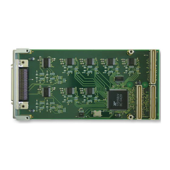
1 Product Description The TPMC461 is a standard single-width 32 bit PMC module and offers 8 channels of high performance serial interface. Three different standard modules are available: The TPMC461-10R provides 8 RS232 interfaces. The TPMC461-11R provides 8 RS422 interfaces. The TPMC461-12R provides 4 RS232 and 4 RS422 interfaces. -
Page 7: Technical Specification
PMC P14 I/O (64 pin Mezzanine Connector) Physical Data Power Requirements TPMC461-10R: 50 mA typical @ +5V DC (no load) TPMC461-11R: 70 mA typical @ +5V DC (no load) TPMC461-12R: 60 mA typical @ +5V DC (no load) Temperature Range Operating -40°C to +85°C... -
Page 8: Table 2-1 : Technical Specification
If FIT rates are not available, MIL-HDBK-217F and MIL-HDBK-217F Notice 2 formulas are used for FIT rate calculation. Humidity 5 – 95 % non-condensing Weight 67 g Table 2-1 : Technical Specification TPMC461 User Manual Issue 1.0.6 Page 8 of 26... -
Page 9: Local Space Addressing
3.2 Device Configuration Space PCI Base Address: XR17D158 PCI Base Address 0 (Offset 0x10 in PCI Configuration Space). The TPMC461 uses the Exar XR17D158 Octal UART to provide and control the 8 channels. Device Configuration Space PCI Address Size Content... -
Page 10: Uart Register Sets
8, 16, 32 0x140 – 0x17F Reserved 0x180 – 0x1FF Read FIFO with errors – 16, 32 64 bytes of RX FIFO data + LSR Table 3-4 : UART Register Set TPMC461 User Manual Issue 1.0.6 Page 10 of 26... -
Page 11: Device Configuration Registers
The Device Configuration Registers control general operating conditions and monitor the status of various functions. This includes a 16 bit general purpose counter, multipurpose input/outputs (not supported by the TPMC461), sleep mode, soft-reset and device identification, and revision. They are embedded inside the UART 0 Register Set. -
Page 12: Uart Channel Configuration Registers
0x0D Reserved 0x00 Xoff-2 – Xoff Character 2 0x0E Reserved 0x00 Xon-1 – Xon Character 1 0x0F Reserved 0x00 Xon-2 – Xon Character 2 Table 3-6 : UART Channel Configuration Registers TPMC461 User Manual Issue 1.0.6 Page 12 of 26... - Page 13 (Offset of the LCR register within a UART register set) For a detailed description of the serial channel registers please refer to the XR17D158 data sheet which is available on the Exar website (www.exar.com). TPMC461 User Manual Issue 1.0.6 Page 13 of 26...
-
Page 14: Xr17D158 Target Chip
00 00 01 00 Table 4-1 : PCI Header Device-ID: 0x01CD TPMC461 Vendor-ID: 0x1498 TEWS TECHNOLOGIES Revision ID: XR17D158 silicon revision Subsystem-ID: 0x000A -10R 0x000B -11R 0x000C -12R Subsystem Vendor-ID: 0x1498 TEWS TECHNOLOGIES TPMC461 User Manual Issue 1.0.6 Page 14 of 26... -
Page 15: Configuration Eeprom
Subsystem Vendor ID 0x2E 0x1498 0x03 Subsystem ID 0x2C s.b. Table 4-2 : Configuration EEPROM TPMC461-xxR Subsystem-ID Value (Offset 0x0C): TPMC461-10R 0x000A TPMC461-11R 0x000B TPMC461-12R 0x000C The words following the configuration data contain: The module version and revision The UART clock frequency in Hz... -
Page 16: Table 4-3 : Physical Configuration Eeprom Data
0x0000 0x0000 0x0000 (Front or Back I/O only) Channels with enhanced RTS & CTS 0x3A 0x0000 0x0000 0x0000 Support for RS232 only 0x3B-0x3F Reserved Table 4-3 : Physical Configuration EEPROM Data TPMC461 User Manual Issue 1.0.6 Page 16 of 26... -
Page 17: Configuration Hints
5 Configuration Hints The following chart shows the UART interface mapping of the different variants of the TPMC461. TPMC461-10R TPMC461-11R TPMC461-12R RS232 RS422 RS232 RS422 RS232 RS422 UART0 UART1 UART2 UART3 UART4 UART5 UART6 UART7 Table 5-1 : UART interface mapping Other configurations are available as factory build option on a per channel base. -
Page 18: Programming Hints
6 Programming Hints 6.1 UART Baud Rate Programming Each of the 8 UART channels of the TPMC461 provides a programmable Baud Rate Generator. The clock of the XR17D158 UART can be divided by any divisor from 1 to 2 – 1. The divisor can be programmed by the UART channel DLM (Divisor MSB) and DLL (Divisor LSB) registers. -
Page 19: Rs422 Flow Control
Only UART channels 0 & 1 allow using RS422 with RTS/CTS flow control. On channels 2 – 7 the CTS# input is hardwired to ’1’, so that no RTS/CTS flow control is possible. TPMC461 User Manual Issue 1.0.6 Page 19 of 26... -
Page 20: Pin Assignment - I/O Connector
Do not apply additional external termination resistors here. Please note that on the TPMC461 the P14 back I/O connector is always populated and connected to on board logic. Do not use these modules on carrier boards where P14/J14 is reserved for other system signals but PMC I/O. -
Page 21: Front Panel I/O Connector
7.1 Front Panel I/O Connector The TPMC461 front panel I/O connector is a HD50 SCSI-2 type female connector (e.g. AMP# 787395-5). 7.1.1 TPMC461-10R Signal Signal Level Signal Signal Level TxD0 RS232 TxD5 RS232 RxD0 RS232 RxD5 RS232 RTS0 RS232 RTS5... -
Page 22: Tpmc461-11R
RS422 CTS0- RS422 CTS0+ RS422 TxD4- RS422 RTS1- RS422 TxD4+ RS422 RTS1+ RS422 RxD4- RS422 CTS1- RS422 RxD4+ RS422 CTS1+ RS422 Table 7-2 : TPMC461-11R Pin Assignment Front Panel I/O Connector TPMC461 User Manual Issue 1.0.6 Page 22 of 26... -
Page 23: Tpmc461-12R
DTR0 RS232 CTS3 RS232 RS232 DSR0 RS232 TxD4- RS422 RS232 TxD4+ RS422 DTR1 RS232 RxD4- RS422 RS232 RxD4+ RS422 DSR1 RS232 Table 7-3 : TPMC461-12R Pin Assignment Front Panel I/O Connector TPMC461 User Manual Issue 1.0.6 Page 23 of 26... -
Page 24: Back I/O Pmc Connector (P14)
CTS3 RS232 TxD4 RS232 RxD4 RS232 RTS4 RS232 CTS4 RS232 TxD5 RS232 RxD5 RS232 RTS5 RS232 CTS5 RS232 TxD6 RS232 Table 7-4 : TPMC461-10R Pin Assignment Back I/O PMC Connector (P14) TPMC461 User Manual Issue 1.0.6 Page 24 of 26... -
Page 25: Tpmc461-11R
RxD3+ RS422 TxD4- RS422 TxD4+ RS422 RxD4- RS422 RxD4+ RS422 TxD5- RS422 TxD5+ RS422 RxD5- RS422 RxD5+ RS422 TxD6- RS422 Table 7-5 : TPMC461-11R Pin Assignment Back I/O PMC Connector (P14) TPMC461 User Manual Issue 1.0.6 Page 25 of 26... -
Page 26: Tpmc461-12R
CTS3 RS232 TxD4- RS422 TxD4+ RS422 RxD4- RS422 RxD4+ RS422 TxD5- RS422 TxD5+ RS422 RxD5- RS422 RxD5+ RS422 TxD6- RS422 Table 7-6 : TPMC461-12R Pin Assignment Back I/O PMC Connector (P14) TPMC461 User Manual Issue 1.0.6 Page 26 of 26...
Need help?
Do you have a question about the TPMC461 and is the answer not in the manual?
Questions and answers