
Related Manuals for Mikroe EasyAVR PRO v8


Summary of Contents for Mikroe EasyAVR PRO v8
- Page 1 EasyAVR PRO v8 D E V E L O P M E N T B O A R D f o r 8 / 16 b i t A V R ® m i c r o c o n t r o l l e r s...
- Page 2 It’s time to rethink the way you approach rapid prototyping Let us introduce you to the latest generation of MIKROE development boards – E a s y A V R P R O v 8 Time-saving embedded tools E a s y A V R P R O v 8 M a n u a l...
-
Page 3: Table Of Contents
Introduction Development board overview Power supply unit Detailed description PSU connectors Power/debug, USB-C connector Power 12VDC, external power supply Battery power supply Power redundancy and uninterrupted power supply (UPS) Powering up the development board Dual power supply CODEGRIP – programmer/debugger module DBG selection Connectivity SiBRAIN... - Page 4 All these features are packed on a single development board, which itself uses innovative manufacturing technologies, delivering fluid and immersive working experience. EasyAVR PRO v8 development board is also an integral part of the MIKROE rapid development ecosystem. Natively supported by the MIKROE Software toolchain, backed up by hundreds of...
-
Page 5: Introduction
E a s y A V R P R O v 8 M a n u a l... -
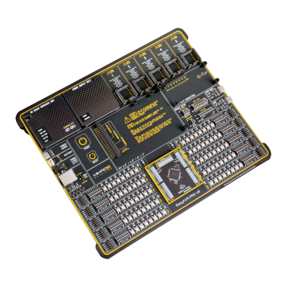
Page 6: Development Board Overview
Development board overview The EasyAVR PRO v8 development board features a clean and intuitive layout, allowing the user to instantly understand how to set it up and how to easily tune it according to needs. The development board is divided into several sections, arranged so that all the related interactive components such as switches, buttons, indicators, and connectors, are logically positioned and grouped together. - Page 7 This allows clean and clutter-free cable management. EasyAVR PRO v8 development board is supported by a powerful CODEGRIP Suite, offering complete control over the EasyAVR PRO v8 development board. It is...
-
Page 8: Power Supply Unit
It is equipped with three diff erent power supply inputs, offering all the flexibility that EasyAVR PRO v8 needs, especially when used on the field. In the case when multiple power sources are used, an automatic power switching circuit with predefined priorities ensures that the most appropriate will be used. -
Page 9: Psu Connectors
When multiple power sources are connected at once, this circuitry is also used to USB Power Supply determine the input priority level: externally connected 12V PSU (2), power over USB (3), and the Li-Po/Li-Ion battery (4). The transition between available power Input Voltage [V] Output Voltage [V] Max Current [A]... -
Page 10: Battery Power Supply
It is advised to disable the battery charging circuitry if there is no battery Power redundancy and uninterrupted connected to the EasyAVR PRO v8 development board. This can be done using CODEGRIP Suite. For more information, please consult the CODEGRIP... -
Page 11: Powering Up The Development Board
MCLR pin of the MCU, allowing the RESET function to be performed. Dual power supply EasyAVR PRO v8 development board supports both 3.3V and 5V power supply on a single board. Advanced PSU module provides the possibility to chose power supply for board and host MCU, between 3.3V (default) and 5V. -
Page 12: Codegrip - Programmer/Debugger Module
USB cable is used. As soon as the USB cable is connected to the host PC, simple examples of what EasyAVR PRO v8 development board can offer. the CODEGRIP module is enumerated and the development board is ready to be used. -
Page 13: Dbg Selection
TDO/MISO/DATA TCK/SCK TDI/MOSI DBG selection The EasyAVR PRO v8 development board is equipped with the RJ-45 connector (2), allowing an external programmer/debugger to be connected. The connector supports a wiring pinout compatible with Microchip ® external programmers/debuggers. In adition, there is a 1x8 male pin header, with a wiring pinout compatible with Microchip®... -
Page 14: Connectivity
™ , with more added on a daily basis. Tight integration of the EasyAVR PRO v8 board with the whole MIKROE ecosystem, allows seamless and effortless prototyping, and truly rapid embedded application development. For more info about the mikroBUS standard and the Click board line of products, please visit the official MIKROE web page at ™... - Page 15 Easily create an IoT Weather Station with the EasyAVR PRO v8 development board. Use the following tools: ∫ EasyAVR PRO v8 development board ∫ G2C click ∫ OLED C click ∫ SiBRAIN for ATmega ∫ Temp-Log 2 click ∫ Thunder click ∫...
-
Page 16: Sibrain
SiBRAIN Due to SiBRAIN add-on board universal nature, EasyAVR PRO v8 development board supports a vast number of different MCUs. In addition, each of the supported MCUs has some specifics, such as the number of pins and ports, additional peripherals, clock speeds, etc. - Page 17 This makes each SiBRAIN card self-contained unit, allowing the development board to operate on a logic level, not having to facilitate specific requirements of many different MCUs. This also allows the MCU to be freely chosen, not having to worry about the pin compatibility and similar issues. Most importantly, it allows very simple swapping between different MCU types during the development phase, without any hardware interventions.
-
Page 18: Input/Output Section
INPUT / OUTPUT section LOW position: a button applies LOW logic level to the corresponding PORT pins (according to 8-bit labeling) In general, I/O pins of any MCU are internally grouped as PORTs. Such pin UP-PULL-DOWN DIP switch grouping scheme is kept throughout the development board as well, offering a clean and organized interface. -
Page 19: 2X5 Pin Headers
IDC10 extension cables, IDC10 female sockets, or simply by using jumper wires. Enhanced connectivity is one of the key features of EasyAVR PRO v8 development board, there are many connectivity options provided. However, 2x5-pin headers allow the most extensive connectivity as they expose all the available GPIO MCU pins to the outside world. -
Page 20: 2X20 Display Connector
2x20 display connector Figure 9: 2x20-pin board connector view EasyAVR PRO v8 development board features a standardized 2x20-pin display connector (1). This connector consists of the 8080 parallel interface, offering support for displays with up to 8 bits per color (up to 24-bit mode, 16 million colors). -
Page 21: 1X16 Display Connector
1x16 display connector Liquid Crystal Display (LCD) is a cheap and popular way of representing application results, messages, or some other type of information to users. EasyAVR PRO v8 natively supports 2x16 characters LCD module, connected in 4-bit mode. It offers a dedicated 1x16-pin header that can host a compatible LCD. -
Page 22: Mikrobus ™ Sockets
™ sockets The superior connectivity features of the EasyAVR PRO v8 development board are rounded up with five standardized mikroBUS host connectors. It ™ is a considerable upgrade for the board, as it allows interfacing with the vast amount of Click boards ™... -
Page 23: Click Boards
They enhance rapid development and accelerate time to market. These ready-to-use boards require no additional hardware configuration. More information at www.mikroe.com/click E a s y A V R P R O v 8 M a n u a l... -
Page 24: Communication
UART TX pin from the FT230XQ IC To set up EasyAVR PRO v8 development board as the USB HOST, the PSW pin should be set to a LOW logic level (0) by the MCU. If set to a HIGH logic level SW2.4... -
Page 25: Additional Gnds
Additional GNDs EasyAVR PRO v8 development board contains two exposed GND pins just above the SiBRAIN card, which can be used to connect measurement or testing equipment. These additional GND pins allow secure connection with the instrumentation probes, avoiding loose cables or unreliable contacts that might compromise the accuracy of the readings. - Page 26 The 8 generation of hardware perfection...
- Page 28 What makes you want to be an embedded developer? Is it the recognition of your skills, invention, or the development process? Whatever the reason is, we want to let you know that we are here for you every step of the way. You can enjoy the process focused, yet relaxed –...
-
Page 30: What's Next
What’s Next? You have now completed the journey through each and every feature of the EasyAVR PRO v8 development board. You have become familiar with its modules, organization, and the programmer/debugger. Now you are ready to start using your new board. We suggest following steps which are highly recommended to begin with. - Page 31 D I S C L A I M E R All the products owned by MikroElektronika are protected by copyright law and international copyright treaty. Therefore, this manual is to be treated as any other copyright material. No part of this manual, including product and software described herein, must be reproduced, stored in a retrieval board, translated or transmitted in any form or by any means, without the prior written permission of MikroElektronika.
- Page 32 If you want to learn more about our products, please visit our website at www.mikroe.com If you are experiencing some problems with any of our products or just need additional information, please place your ticket at www.mikroe.com/support If you have any questions, comments or business proposals, do not hesitate to contact us at office@mikroe.com...
Need help?
Do you have a question about the EasyAVR PRO v8 and is the answer not in the manual?
Questions and answers