Advertisement
Quick Links
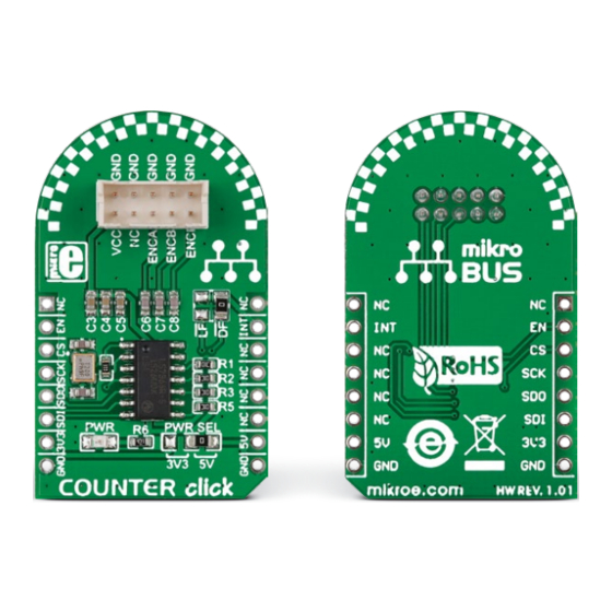
COUNTER
click
1. Introduction
Counter click carries an LS7366R quadra-
ture counter. The top of the board has a
pinout for interfacing with incremental en-
coders. The interface has ENCA and ENCB
pins, along with ENCI, which is a program-
mable index. On the other side, Counter
click communicates with the target board
microcontroller through the mikroBUS™
SPI interface (CSK, MISO, MOSI), plus enable
(CNT EN) and interrupt (LFLAG or DFLAG)
pins. The board can use either a 3.3V or a
5V power supply.
2. Soldering the headers
Before using your click board
™
, make sure
to solder 1x8 male headers to both left and
right side of the board. Two 1x8 male headers
are included with the board in the package.
2
Turn the board upside down so that
the bottom side is facing you upwards.
Place shorter pins of the header into the
appropriate soldering pads.
1
3
Turn the board upward again. Make sure
to align the headers so that they are
perpendicular to the board, then solder the
pins carefully.
3. Plugging the board in
Once you have soldered the headers your
board is ready to be placed into the desired
mikroBUS
socket. Make sure to align the cut
™
in the lower-right part of the board with the
markings on the silkscreen at the mikroBUS
socket. If all the pins are aligned
correctly, push the board all the
way into the socket.
4. Essential features
Incremental encoders output A and B pulses
which are out of phase to each other, ideally
by 90º. The LS7366R CMOS counter takes
these signals as inputs. The decoded input is
then used for non-quadrative, up/down, free
running counting (the IC has many count-
ing modes). Applications include measure-
ment of the direction and RPM of DC motor
shafts. This data can be used for monitoring
and ensuring the proper operation of shafts
in industrial, robotic and a number of other
domains. The chip has multiple operating
modes.
click
™
BOARDS
www.mikroe.com
™
Counter click Manual v101
Counter click Manual v101
0 1 0 0 0 0 0 0 8 9 4 0 8
Advertisement

Related Manuals for Mikroe COUNTER click


Summary of Contents for Mikroe COUNTER click
- Page 1 The chip has multiple operating appropriate soldering pads. pins carefully. modes. 1. Introduction Counter click carries an LS7366R quadra- 3. Plugging the board in click ture counter. The top of the board has a pinout for interfacing with incremental en- Once you have soldered the headers your coders.
- Page 2 25.4 1000 WIDTH the present schematic are subject to change Counter click has two SMD jumpers (zero ohm HEIGHT* at any time without notice. resistor). One lets you switch between a 3.3V or a 5V power supply. The other is for setting 42.9 mm / 1690 mils...
Need help?
Do you have a question about the COUNTER click and is the answer not in the manual?
Questions and answers