Advertisement
Quick Links
Advertisement

Related Manuals for Mikroe CLICKER 4 For TMPM4K


Summary of Contents for Mikroe CLICKER 4 For TMPM4K
- Page 1 C L I C K E R 4 f o r T M P M 4 K U S E R M A N U A L...
- Page 2 Thank you for choosing MIKROE! We present you the ultimate solution for embedded development. Elegant on the surface, yet extremely powerful on the inside, we have designed it to inspire outstanding achievements. And now, it’s all yours. Enjoy premium. Time-saving embedded tools...
-
Page 3: Table Of Contents
Table of contents Introduction 1. MCU Features 2. MCU Programming 3. MCU Reset 4. Buttons and LEDs 5. Power Supply 6. Connectivity 7. Click boards ™... -
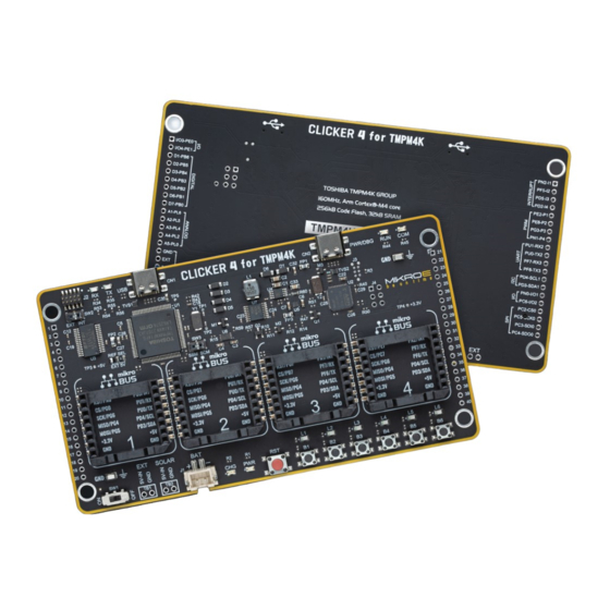
Page 5: Introduction
Clicker 4 for TMPM4K is a compact development board Besides two 1x20 pin headers, four improved mikroBUS ™ designed as a complete solution, you can use it to quickly sockets represent the most distinctive connectivity feature, build your own gadgets with unique functionalities. -
Page 6: Mcu Features
∫ Advanced vector engine plus (A-VE+) ∫ Advanced Encoder input circuit (32-bit) (A-ENC32) For the complete list of MCU features, please refer to the TMPM4KNFYAFG datasheet. CLICKER 4 for TMPM4K U S E R M A N U A L... -
Page 7: Mcu Programming
Debug Port to USB. Debuggers, which execute LEDs RUN and COM blink one time. on a host computer, connect via USB to the Debug Unit and to CLICKER 4 for TMPM4K U S E R M A N U A L... - Page 8 2x5 JTAG/SWD connector soldered on the addapter might be needed. J2 connector pads. CLICKER 4 for TMPM4K U S E R M A N U A L CLICKER 4 for TMPM4K U S E R M A N U A L...
-
Page 9: Mcu Reset
It is used to generate a LOW logic level on the MCU the MCU. reset pin. Figure 4: Clicker 4 for TMPM4K front view CLICKER 4 for TMPM4K U S E R M A N U A L... -
Page 10: Buttons And Leds
MCU pin, and an active LED indicates that a logic high (1) is present. Figure 5: Buttons and LEDs view CLICKER 4 for TMPM4K U S E R M A N U A L CLICKER 4 for TMPM4K U S E R M A N U A L... -
Page 11: Power Supply
There are five power supply connectors available, each with its unique purpose: CN1, CN2: USB-C connector Standard 2.5mm pitch XH battery connector TB1, TB2: A place for a standard 2.54mm terminal block (3,4) CLICKER 4 for TMPM4K U S E R M A N U A L... -
Page 12: Connectivity
MCU pins. Figure 7: mikroBUS sockets view ™ CLICKER 4 for TMPM4K U S E R M A N U A L CLICKER 4 for TMPM4K U S E R M A N U A L... - Page 13 GPIO INTERRUPT DIGITAL UART ANALOG SCL1 SDA1 GPIO 3.3V SPIO MISO VREF MOSI RESET Figure 8: 1x20 pin header view INTERRUPT UART ANALOG DIGITAL CLICKER 4 for TMPM4K U S E R M A N U A L...
-
Page 14: Click Boards
They enhance rapid development and accelerate time to market. These ready-to-use boards require no additional hardware configuration. More information at www.mikroe.com/click Figure 9: Click boards ™ connected CLICKER 4 for TMPM4K U S E R M A N U A L... - Page 15 D I S C L A I M E R All the products owned by MikroElektronika are protected by copyright law and international copyright treaty. Therefore, this manual is to be treated as any other copyright material. No part of this manual, including product and software described herein, must be reproduced, stored in a retrieval system, translated or transmitted in any form or by any means, without the prior written permission of MikroElektronika.
- Page 16 If you are experiencing some problems with any of our products or just need additional information, please place your ticket at www.mikroe.com/support Time-saving embedded tools If you have any questions, comments or business proposals, do not hesitate to contact us at office@mikroe.com...
Need help?
Do you have a question about the CLICKER 4 For TMPM4K and is the answer not in the manual?
Questions and answers