Table of Contents
Advertisement
Quick Links
Advertisement
Table of Contents

Subscribe to Our Youtube Channel
Related Manuals for Mikroe EasyAVR v8


Summary of Contents for Mikroe EasyAVR v8
- Page 1 E a s y A V R v 8 D E V E L O P M E N T B O A R D E a s y A V R v 8 M a n u a l...
- Page 2 It’s time to rethink the way you approach rapid prototyping Let us introduce you to the latest generation of MIKROE development boards – E a s y A V R v 8 Time-saving embedded tools E a s y A V R v 8 M a n u a l...
-
Page 3: Table Of Contents
Introduction Development board overview Power supply unit Detailed description Voltage reference Programming voltage PSU connectors Power/debug, USB-C connector Power 12VDC, external power supply Battery power supply Power redundancy and uninterrupted power supply (UPS) Powering up the development board Dual power supply VDDIO2 CODEGRIP –... - Page 4 E a s y A V R v 8 M a n u a l...
-
Page 5: Introduction
The with only 8 pins, all the way up to 40-pin "giants". EasyAVR v8 development board is also an integral part of the Mikroe rapid development ecosystem. Natively supported by the Mikroe The development board supports the well-established mikroBUS Software toolchain, backed up by hundreds of different Click board ™... -
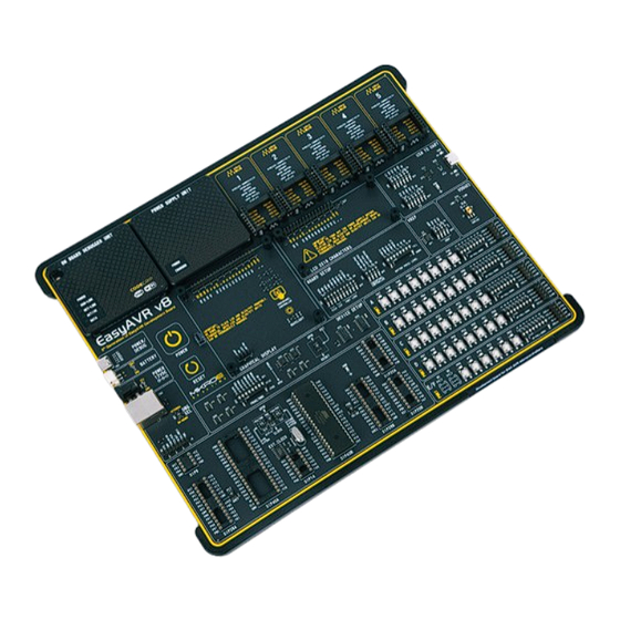
Page 6: Development Board Overview
Development board overview The EasyAVR v8 development board features a clean and intuitive layout, allowing the user to instantly understand how to set it up and how to easily tune it according to needs. The development board is divided into several sections, arranged so that all the related interactive components such as switches, buttons, indicators, and connectors, are logically positioned and grouped together. - Page 7 ™ www.mikroe.com The EasyAVR v8 development board is equipped with two display connectors, located in the middle section of the board. One connector is a 1x16 pin header used for connecting a character-based LCD in 4-bit mode. The second display connector is a single row 20 pin header, which supports monochromatic GLCD and EasyTFT board.
-
Page 8: Power Supply Unit
It is equipped with three different power supply inputs, offering all the flexibility that EasyAVR v8 needs, especially when used on the field. In the case when multiple power sources are used, an automatic power switching circuit with predefined priorities ensures that the most appropriate will be used. -
Page 9: Voltage Reference
response and high efficiency for light loads. Each of the two buck regulators is used to supply power to the corresponding power supply rail (3.3V and 5V), throughout the entire development board and connected peripherals. Voltage reference The PSU is able to provide a very accurate, programmable voltage reference (VREF) in the range from 0V to 4.096V. -
Page 10: Psu Connectors
PSU connectors As explained, the advanced design of the PSU allows several types of power sources to When using a PC as a power source, the maximum power can be obtained if the host PC supports the USB 3.2 interface and is equipped with USB-C connectors. If the host be used, offering unprecedented flexibility: when powered by a Li-Po/Li-ION battery, it offers an ultimate degree of autonomy. -
Page 11: Battery Power Supply
Combined with the fact that the board can be remotely significant USB voltage drop, which can obstruct the battery charging process. programmed and debugged over the WiFi network, the EasyAVR v8 development board allows complete autonomy, allowing it to be used in some very specific situations: hazardous environments, agricultural applications, etc. -
Page 12: Power Redundancy And Uninterrupted Power Supply (Ups)
VDDIO2 voltage between the 1.8V, 3.3V and 5V. Additionaly, next to the DIP28B socket there is a switch used to select either EasyAVR v8 development board supports both 3.3V and 5V power supply on a single VDDIO2 or GPIO for the MCUs pin supporting this functionality: board. -
Page 13: Codegrip Programmer/Debugger Module
CODEGRIP programmer/debugger module is supported by CODEGRIP Suite. Detailed package, the EasyAVR v8 development board is equipped with the onboard CODEGRIP explanation on how to configure and use the CODEGRIP module on the EasyAVR v8 programming/debugging module, to support programming/debugging feature. -
Page 14: Prog/Debug
PROG/DEBUG SW2.7 (DIP20B) SPI (up): connects the PB0, PB1 and PB2 pins to the SPI interface of the CODEGRIP programmer/debugger module or external device There are multiple switch ICs located in the DEVICE SETUP section, used for SPI and JTAG GPIO (middle): allows the PB0, PB1 and PB2 pins to be used as GPIO lines multiplexing. -
Page 15: Dbg Selection
Figure 6: Programmer/debugger view DBG selection The EasyAVR v8 development board is equipped with the RJ-45 connector ONBOARD (down): Interface is enabled. If an external debugger probe-device and a 1x8 pin header (2); allowing an external programmer/debugger is connected, there is a possible collision in communication. -
Page 16: Connectivity
The EasyAVR v8 development board supports all 8-bit AVR MCUs in DIP package type. To allow this, the development board offers a total of eight DIP socket sizes: DIP8, DIP14, DIP20 [A, B], DIP28 [A, B], and DIP40 [A, B]. - Page 17 Easily create an IoT Weather Station with the EasyAVR v8 development board. Use the following tools: EasyAVR v8 development board EasyTFT board G2C click OLED C click Temp-Log 2 click Thunder click LPS22HB click E a s y A V R v 8 M a n u a l...
-
Page 18: Mcu Sockets
Figure 7: Main board with MCU socket section view MCU sockets As previously mentioned, the EasyAVR v8 development board supports all 8-bit AVR MCUs in DIP package type. There are eight different sockets, ranging from DIP8 (8-pin DIP socket), up to DIP40 (40-pin DIP socket). All DIP sockets are grouped in the lower left area of the board (1). -
Page 19: Vcap And Vcc
Crystal oscillator AVR microcontrollers can use either built-in (internal) or quartz-crystal external clock for the purpose of providing clock signal source. The EasyAVR v8 contains one quartz- crystal socket for all microcontroller sockets. DIP40A and DIP40B sockets are directly connected to quartz-crystal socket unlike DIP28A/B, DIP20A/B, DIP14 and DIP8 sockets which are connected to it through the selection switches (SW10, SW19 and SW22). -
Page 20: Input/Output Section
There are five PORTs on the EasyAVR v8 development board, labeled from PORTA to PORTE/F. Depending on the pin-count of the MCU, not all PORTs will be used. However, the development board supports the highest pin-count MCUs in DIP package type (40 pins). -
Page 21: 2X5 Pin Headers
GND and the power rails. The pins on these headers are labeled according to the names of the MCU pins to which they are routed. These 2x5 pin headers can be used to expand the connectivity of the EasyAVR v8 development board, allowing interfacing with other devices, peripherals, and measurement equipment, either by using IDC10 extension cables, IDC10 female sockets, or simply by using jumper wires. -
Page 22: 1X20 Glcd Graphical Display Connector
EasyAVR v8 development board. Two poles of the SW3 DIP switch (4), grouped under the GLCD label, are used to The board is primarily designed to be used as a display board on Mikroe Easy control the backlight options of the GLCD: development boards. - Page 23 Figure 9: 1x20 pin board connector view E a s y A V R v 8 M a n u a l E a s y P I C v 8 M a n u a l...
- Page 24 Figure 10: 1x16 display header view...
-
Page 25: 1X16 Lcd Character Display Connector
The EasyAVR v8 development board natively supports 2x16 character LCD module, connected in 4-bit mode. It offers a dedicated 1x16 pin header that can host a compatible LCD module. -
Page 26: Mikrobus ™ Sockets
™ sockets The superior connectivity features of the EasyAVR v8 development board are rounded up with five standardized mikroBUS host connectors (1). It is a considerable upgrade ™ for the board, as it allows interfacing with the vast amount of Click boards ™... -
Page 27: Click Boards
They enhance rapid development and accelerate time to market. These ready-to-use boards require no additional hardware configuration. More information at www.mikroe.com/click E a s y A V R v 8 M a n u a l... -
Page 28: Communication
MCU and other external devices. The EasyAVR v8 development board offers the UART connectivity over the USB-C connector by utilizing the FT230XQ (3), a popular USB-UART signal conversion IC, produced by FTDI Chip. -
Page 29: Additional Gnds
Red LED (RX) indicates incoming data transfer Additional GNDs The EasyAVR v8 development board contains exposed GND pins which can be used to connect measurement or testing equipment. These additional GND pins allow secure connection with the instrumentation probes, avoiding loose cables or unreliable contacts that might compromise the accuracy of the readings. - Page 30 What makes you want to be an embedded developer? Is it the recognition of your skills, invention, or the development process? Whatever the reason is, we want to let you know that we are here for you every step of the way. You can enjoy the process focused, yet relaxed –...
-
Page 32: What's Next
We invite you to join thousands of users of MIKROE development tools. You will find useful MIKROE offers free Tech Support to the end of its life span, so if anything goes wrong, we projects and tutorials and get help from a large user community. If you want to download are ready and willing to help. - Page 33 (including damages for loss of business profits and business information, business interruption or any other pecuniary loss) arising out of the use of this manual or product, even if MIKROE has been advised of the possibility of such damages. MIKROE reserves the right to change information contained in this manual at any time without prior notice, if necessary.
- Page 34 If you want to learn more about our products, please visit our website at www.mikroe.com If you are experiencing some problems with any of our products or just need additional information, please place your ticket at www.mikroe.com/support Time-saving embedded tools If you have any questions, comments or business proposals, do not hesitate to contact us at office@mikroe.com...
Need help?
Do you have a question about the EasyAVR v8 and is the answer not in the manual?
Questions and answers