Advertisement
Description
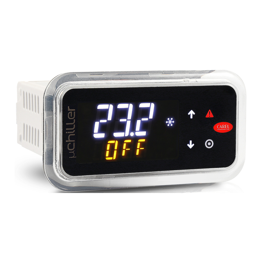
μChiller is the Carel solution for complete management of air/water and water/water chillers and heat pumps. The maximum configuration manages 2 compressors per circuit (On/Off or BLDC), up to a maximum of 2 circuits (using an expansion card for the inputs and outputs on circuit 2). The distinctive element of μChiller is complete control of high-efficiency units through integrated management of electronic expansion valves and brushless DC compressor, thus ensuring greater compressor protection and reliability, together with high unit efficiency. The user terminal allows wireless connectivity with mobile devices and is integrated into the panel-mounted models, or purchased separately on DIN rail mounted models. The CAREL "APPLICA" app, available on Google Play for the Android operating system, facilitates configuration of the parameters and unit commissioning in the field. The operation of μChiller is described in the user manual + 0300053EN downloadable, even prior to purchase, from the website www.carel.com.
USER TERMINAL

key
- Keypad
- Main field
- Icons: device status & operating mode
![]()
Icons
Keypad
| Button | Function | |
 | UP | Navigation: previous parameter Parameter setting: increase value |
 | DOWN | Navigation: next parameter MAIN MENU: |
 | Alarm | Pressed briefly: display active alarms and mute buzzer. Pressed and held (3 s): reset alarms. |
 | PRG | During navigation: access the parameter setting menu During parameter setting:
|
MOBILE DEVICE
The "Applica" app can be used to configure the µChiller controller from a mobile device (smartphone, tablet), via NFC (Near Field Communication) or BLE (Bluetooth Low Energy). Procedure (modify parameters):
- download the CAREL "Applica" app for Android devices from Google Play Store;

- (on the mobile device) activate NFC/Bluetooth communication and data connection;
- open Applica;
Using NFC
- move the mobile device near to the user terminal, maximum distance 10 mm, so as to recognise the configuration;
![]()
- enter the password (*);
- set the parameters as needed;
- move the mobile device near to the user terminal again to upload the configuration parameters;
![]()


Using BLE
- move the mobile device near to the user terminal, maximum distance 10 m, to recognise the configuration;
![]()
- enter the password (*);
- set the parameters as needed.

(*) pre-assigned by the chiller manufacturer to allow maintenance only by authorised service technicians.

during the first connection, Applica aligns itself with the software version on the µChiller controller via a cloud connection; this means a mobile data connection is needed at least for this first connection.
COMMISSIONING
The procedure for initial commissioning is described below.
PREPARATION
Before configuring the unit the first time, access KSA (ksa.carel.com), select the "Configurations" folder and:
- for the μChiller Standard and Enhanced models (with On/Off compressor) select the "Refrigerants" section and then the refrigerant charged in the unit;
- for HE models (with BLDC compressor), import the BLDC configuration, selecting the "BLDC compressors" section and then the brand and model of compressor installed on the unit (this already includes the refrigerant setting)
- import the downloaded configuration into the mobile device.
CONFIGURATION
- start Applica and access the Manufacturer and Service profiles;
- select Set-up -> Configuration and click the + icon (see image)

- use the menu (Fig. a) to select and apply the desired configuration;
![]()
- select Unit Set-up (Fig. b) to proceed with the complete configuration (Fig c).


ALARM TABLE


TECHNICAL SPECIFICATIONS (for both models)
Technical specifications, μChiller PANEL and DIN
 Physical specifications

Environmental conditions
 Electrical characteristics
 User interface
 Connectivity
 Analogue inputs (Lmax=10m)

Digital inputs

Valve output

Analogue outputs
 Digital outputs
Note: the sum of the current drawn by NO1, NO2, NO3 and N04 must not exceed 8A.
 Emergency power supply
 Probe and terminal power supply
 Cable lengths
 Conformity
PANEL MOUNTING MODEL
Dimensions


Mounting

Place the controller in the opening, press lightly on the side tabs and then on the front until fully inserted (the side tabs will bend, and the catches will attach the controller to the panel).
IP65 front protection is guaranteed only if the following conditions are met:
- maximum deviation of the rectangular opening from flat surface: ≤ 0.5 mm;
- thickness of the electrical panel sheet metal: 0.8-2 mm;
- maximum roughness of the surface where the gasket is applied: ≤ 120 μm.
Note: the thickness of the sheet metal (or material) used to make the electrical panel must be adequate to ensure safe and stable mounting of the product.
Disassembly
Open the electrical panel from the rear and press the anchoring tabs and then the controller to remove it.

The operation does not require the use of a screwdriver or other tools.

DIN RAIL MOUNTING
Dimensions

Mounting

WIRING CONNECTION
Connection: panel mounting

Connection: DIN rail mounting

Probe connection

0-10 Vdc NTCprobe connection

NTCprobe connection

Ratiometric probe connection

4-20mA probe connection
Note:  = GND
= GND
CAREL INDUSTRIES HQs
Via de l'Industria, 11 - 35020 Brugine - Padova (Italy)
Tel. (+39) 0499716611 – Fax (+39) 0499716600
e-mail: carel@carel.com – www.carel.com

Documents / Resources
References
Download manual
Here you can download full pdf version of manual, it may contain additional safety instructions, warranty information, FCC rules, etc.
Download Carel uChiller - Electronic Control For Chiller And Heat Pump Manual
Advertisement


Need help?
Do you have a question about the uChiller and is the answer not in the manual?
Questions and answers