Table of Contents
Advertisement
Advertisement
Table of Contents

Subscribe to Our Youtube Channel
Related Manuals for Carel µC2


Summary of Contents for Carel µC2
- Page 1 µC Manuale d’uso User guide...
- Page 3 Vogliamo farvi risparmiare tempo e denaro! We wish to save you time and money! Vi assicuriamo che la completa lettura di questo We can assure you that the thorough reading of this manual will guarantee correct installation and manuale vi garantirà una corretta installazione ed un sicuro utilizzo del prodotto descritto.
-
Page 5: Table Of Contents
INDICE CONTENTS INTRODUZIONE INTRODUCTION Descrizione generale General description Interfaccia utente User interface COLLEGAMENTI CONNECTIONS Schema generale General diagram Network layout Struttura rete APPLICAZIONI APPLICATIONS PARAMETRI PARAMETERS Parametri generali General parameters Struttura menù Menu structure Tabelle parametri Parameter tables DESCRIZIONE DEI PARAMETRI DESCRIPTION OF THE PARAMETERS TABELLA ALLARMI TABLE OF ALARMS... -
Page 7: Introduzione
• dispositivo di segnalazione di allarme. 1.1.3 Programmazione 1.1.3 Programming CAREL offre la possibilità di configurare tutti i parametri della macchina CAREL offers the possibility to configure all the unit parameters not non solo tramite la tastiera posta sul frontale ma anche da: only from the keypad on the front panel, but also using: •... - Page 8 Fig. 1.2.1.1 Fig. 1.2.1.2 Simbolo Colore Significato Circuito frigorifero di riferimento Symbol Colour Meaning Reference refrigerant circuit con LED acceso con LED lampeggiante with LED ON with LED flashing 1; 2 Ambra Compressore 1 e/o 2 acceso Richiesta di accensione Amber Compressor 1 and/or 2 ON Start up request...
- Page 9 1.2.3. Funzioni associate ai tasti 1.2.3. Functions associated with the buttons Tasto Stato della macchina Modalità pressione Button Unit status Button press mode Caricamento valori di default Accensione con tasto premuto Loading default values Press at power ON Ritorno al sottogruppo superiore all’interno dell’ambiente di programmazione fino Pressione singola all’uscita (con salvataggio variazioni in EEPROM) Press once...
-
Page 10: Collegamenti
2. COLLEGAMENTI 2.CONNECTIONS 2.1 Schema generale 2.1 General diagram EV driver EV driver ESP. Fig. 2.1.1 EV driver EV driver ESP. Fig. 2.1.2 - cod. +030220420 - rel. 2.0 - 18.10.04 µC... -
Page 11: Struttura Rete
2.2 Struttura rete 2.2 Network layout EV driver Fig. 2.2.1 EV driver EV driver Fig. 2.2.2 - cod. +030220420 - rel. 2.0 - 18.10.04 µC... -
Page 12: Applicazioni
3. APPLICAZIONI 3.APPLICATIONS 3.1 Unità ARIA/ARIA, monocircuito 3.1 Air/air unit, single circuit Fig. 3.1.1 3.2 Air/air unit, two circuits 3.2 Unità ARIA/ARIA, bicircuito Fig. 3.2.1 - cod. +030220420 - rel. 2.0 - 18.10.04 µC... - Page 13 3.3 Unità ARIA/ARIA, bicircuito, 1 circuito di 3.3 Air/air unit, two circuits, 1 condenser fan circuit ventilazione di condensazione Sonda mandata Supply probe Fig. 3.3.1 3.4 Pompa di calore ARIA/ARIA, monocircuito 3.4 AIR/AIR heat pump, single circuit Sonda mandata Supply probe Fig.
- Page 14 3.5 Pompa di calore ARIA/ARIA, bicircuito 3.5 AIR/AIR heat pump, two circuits Sonda mandata Supply probe Fig. 3.5.1 3.6 AIR/AIR heat pump two circuits, 1 condenser fan 3.6 Pompa di calore ARIA/ARIA bicircuito, 1 circuito di circuit ventilazione di condensazione Sonda mandata Supply probe Fig.
- Page 15 3.7 Chiller ARIA/ACQUA, monocircuito 3.7 AIR/WATER chiller, single circuit Fig. 3.7.1 3.9 Chiller ARIA/ACQUA, bicircuito, 2 circuiti di 3.9 AIR/WATER chiller, two circuits, 2 condenser fa ventilazione di condensazione e 2 evaporatori circuits and 2 evaporators Fig. 3.9.1 - cod. +030220420 - rel. 2.0 - 18.10.04 µC...
- Page 16 3.10 Chiller ARIA/ACQUA bicircuito, 1 circuito di 3.10 AIR/WATER chiller two circuits, 1 condenser ventilazione di condensazione fan circuit Fig. 3.10.1 3.11 Pompa di calore ARIA/ACQUA, monocircuito 3.11 AIR/WATER heat pump, single circuit Fig. 3.11.1 - cod. +030220420 - rel. 2.0 - 18.10.04 µC...
- Page 17 3.12 Pompa di calore ARIA/ACQUA, 2 circuiti di 3.12 AIR/WATER heat pump, 2 condenser fan circuits ventilazione condensazione Fig. 3.12.1 3.13 Pompa di calore ARIA/ACQUA, bicircuito, 3.13 AIR/WATER heat pump, two circuits, 1 condenser 1 circuito di ventilazione di condensazione fan circuit Fig.
- Page 18 3.14 Chiller ACQUA/ACQUA, monocircuito 3.14 WATER/WATER chiller, single circuit Fig. 3.14.1 3.15 Chiller ACQUA/ACQUA bicircuito 3.15 WATER/WATER chiller two circuits Fig. 3.15.1 - cod. +030220420 - rel. 2.0 - 18.10.04 µC...
- Page 19 3.16 Chiller ACQUA/ACQUA, bicircuito, 1 evaporatore 3.16 WATER/WATER chiller, two circuits, 1 evaporator Fig. 3.16.1 3.17 Pompa di calore ACQUA/ACQUA a reversibilità 3.17 WATER/WATER heat pump with reversal on gas del gas, monocircuito circuit, single circuit Fig. 3.17.1 - cod. +030220420 - rel. 2.0 - 18.10.04 µC...
- Page 20 3.18 Pompa di calore ACQUA/ACQUA a reversibilità 3.18 WATER/WATER heat pump with reversal on gas del gas, bircuito circuit, two circuits Fig. 3.18.1 3.19 Pompa di calore ACQUA/ACQUA a reversibilità 3.19 WATER/WATER heat pump with reversal on gas del gas, bicircuito, 1 evaporatore circuit, two circuits, 1 evaporator Fig.
- Page 21 3.20 Pompa di calore ACQUA/ACQUA a reversibilità 3.20 WATER/WATER heat pump with reversal on water dell’acqua, monocircuito circuit, single circuit Fig. 3.20.1 3.21 WATER/WATER heat pump with reversal on water 3.21 Pompa di calore ACQUA/ACQUA a reversibilità dell’acqua, bicircuito, H02= 1 e H21= 4 circuit, two circuits, H02= 1 e H21= 4 cooling Fig.
- Page 22 3.22 Pompa di calore ACQUA/ACQUA a reversibilità 3.22 WATER/WATER heat pump with reversal on water dell’acqua, bicircuito, 1 evaporatore H02= 1 e H21= 4 circuit, two circuits, 1 evaporator H02= 1 e H21= 4 Fig. 3.22.1 3.23 Motocondensante ad aria senza inversione di 3.23 Air-cooled condensing unit without reverse cycle, ciclo, monocircuito single circuit...
- Page 23 3.24 Air-cooled condensing unit without reverse cycle, 3.24 Motocondensante ad aria senza inversione di two circuits ciclo, bicircuito Fig. 3.24.1 3.25 Reverse-cycle air-cooled condensing unit, single 3.25 Motocondensante ad aria con inversione di ciclo, circuit monocircuito Fig. 3.25.1 - cod. +030220420 - rel. 2.0 - 18.10.04 µC...
- Page 24 3.26 Motocondensante ad aria con inversione di ciclo, 3.26 Reverse-cycle air-cooled condensing unit, two bicircuito con un circuito ventilazione di condensazione circuits with one condenser fan circuit Fig. 3.26.1 3.27 Motocondensante ad acqua senza inversione di 3.27 Water-cooled condensing unit without reverse ciclo, monocircuito cycle, single circuit Fig.
- Page 25 3.28 Motocondensante ad acqua senza inversione di 3.28 Water-cooled condensing unit without reverse ciclo, bicircuito cycle, two circuits Fig. 3.28.1 3.29 Motocondensante ad acqua con inversione di 3.29 Reverse-cycle water-cooled condensing unit, ciclo, monocircuito single circuit Fig. 3.29.1 - cod. +030220420 - rel. 2.0 - 18.10.04 µC...
-
Page 26: Parametri
3.30 Motocondensante ad acqua con inversione di 3.30 Reverse-cycle water-cooled condensing unit, two ciclo, bicircuito circuits Fig. 3.30.1 4.Parameters 4. Parametri 4.1 Parametri generali 4.1 General parameters I parametri si dividono in 4 diverse tipologie a seconda della loro The parameters are divided into 4 different types, according to their accessibilità... -
Page 27: Struttura Menù
4.2 Struttura menù 4.2 Menu structure Livello Nome Livello Password For 5” Level Level name Menù principale Direct No password Main Menù User Super User For 5” Save in the EEPROM Factory Inserimento Password Setting Password Livello Parametri Valore Parametri Parameter Level Parameter Values Parametri /*... -
Page 28: Tabelle Parametri
4.3 Tabelle parametri 4.3 Parameter tables Di seguito sono riportate le tabelle dei parametri suddivise per tipo di The following tables show of the parameters divided by type/family (e. famiglia (es. compressore, sonde, ventilatori ecc.). g. compressor, probes, fans etc.). •... - Page 29 Parametri impostazione sonde/ Probe setting parameters Indicaz. Parametro e descrizione Livello Min. Max. U.M. Variazione Default Visibilità Variabile Tipo Parameter and description Default Min. Max. U.O.M. Variation Default Visibility Superv. Display Variabile. Display Default Supervis. Variabile Indication Level Variable Type Valore minimo pressione/ Pressure min.
- Page 30 4.3.3 Parametri lettura sonde (B*) 4.3.3 Probe reading parameters (B*) Parametri lettura sonde/ Probe reading parameters Indicaz. Parametro e descrizione Livello Min. Max. U.M. Variazione Default Visibilità Variabile Tipo Parameter and description Default Min. Max. U.O.M. Variation Default Visibility Superv. Display Variabile.
- Page 31 4.3.4 Parametri impostazione compressori (c*) 4.3.4 Compressor setting parameters (c*) Parametri lettura sonde/ Compressor setting parameters Indicaz. Parametro e descrizione Livello Min. Max. U.M. Variazione Default Visibilità Variabile Tipo Display Parameter and description Default Min. Max. U.O.M. Variation Default Visibility Superv. Variabile.
- Page 32 4.3.5 Parametri impostazione sbrinamento (d*) 4.3.5 Defrost setting parameters (d*) Parametri lettura sonde/ Compressor setting parameters Indicaz. Parametro e descrizione Livello Min. Max. U.M. Variazione Default Visibilità Variabile Tipo Display Parameter and description Default Min. Max. U.O.M. Variation Default Visibility Superv. Variabile.
- Page 33 4.3.6 Parametri impostazione ventilatori (F*) 4.3.6 Fan setting parameters (F*) Parametri impostazione ventilatori/ Fan setting parameters Indicaz. Parametro e descrizione Livello Min. Max. U.M. Variazione Default Visibilità Variabile Tipo Display Parameter and description Default Min. Max. U.O.M. Variation Default Visibility Superv. Variabile.
- Page 34 4.3.7 Parametri impostazione macchina (H*) 4.3.7 Unit setting parameters (H*) Parametri impostazione macchina/ Unit setting parameters Indicaz. Parametro e descrizione Livello Min. Max. U.M. Variazione Default Visibilità Variabile Tipo Parameter and description Default Min. Max. U.O.M. Variation Default Visibility Superv. Display Variabile.
- Page 35 Parametri impostazione macchina/ Unit setting parameters Indicaz. Parametro e descrizione Livello Min. Max. U.M. Variazione Default Visibilità Variabile Tipo Display Parameter and description Default Min. Max. U.O.M. Variation Default Visibility Superv. Variabile. Display Default Supervis. Variabile Indication Level Variable Type Ingresso digitale Estate/Inverno Flag 14 (R/W) Digital...
- Page 36 4.3.8 Parametri impostazione allarmi (P*) 4.3.8 Alarm setting parameters (P*) Parametri Impostazione Allarmi/ Alarm setting parameters Indicaz. Parametro e descrizione Livello Min. Max. U.M. Variazione Default Visibilità Variabile Tipo Parameter and description Default Min. Max. U.O.M. Variation Default Visibility Superv. Display Variabile.
- Page 37 4.3.9 Parametri impostazioni regolazione (r*) 4.3.9 Control setting parameters (r*) Parametri Impostazione regolazione/ Control setting parameters Indicaz. Parametro e descrizione Livello Min. Max. U.M. Variazione Default Visibilità Variabile Tipo Display Parameter and description Default Min. Max. U.O.M. Variation Default Visibility Superv. Variabile.
- Page 38 4.3.10 Parametri firmware (F-r*) 4.3.10 Firmware parameters (F-r*) Parametri Firmware/ Firmware parameters Indicaz. Parametro e descrizione Livello Min. Max. U.M. Variazione Default Visibilità Variabile Tipo Display Parameter and description Default Min. Max. U.O.M. Variation Default Visibility Superv. Variabile. Display Default Supervis.
-
Page 39: Descrizione Dei Parametri
5. Descrizione dei parametri 5. Description of the parameters Per la modifica dei parametri vedi il capitolo 4 “Parametri.” To modify the parameters, see chapter 4 “Parameters. ” • Impostazione sonde: parametri (/*) • Probe settings: parameters (/*) (vedi tab. 4.3.1 pag. 29) (see Table. - Page 40 Type of unit Temp control Antifreeze Cond. temp Press. probe Antifreeze Cond. temp Press. probe Parameter H01 probe probe probe 1st circuit probe probe 2nd circuit 1st circuit 1st circuit 2nd evaporator 2nd circuit 0= air/air B2 (low outlet Not used temperature) 1= air/air heat pump B2 (low outlet...
- Page 41 Operating diagram of the antifreeze alarm and the antifreeze heaters antigelo per chiller e pompe di calore aria/acqua, acqua/acqua for air/water and water/water chillers and heat pumps. Sonde NTC CAREL (Modalità H1=2, 3, 4, 5 e 6) CAREL NTC Probes Differ. allarme antigelo (A2) Differ.
- Page 42 - Set resistenza antigelo in sbrinamento/appoggio in riscaldamento - Antifreeze heater in defrost/auxiliary heater in heating set point (modalità Inverno) A08: Represents the threshold below which the auxiliary heater is ON in defrost and in heating mode. In the heat pumps (H01=1-3-6), A08: Determina la soglia sotto la quale vengono accese le resistenze di appoggio sia in sbrinamento che in riscaldamento.
- Page 43 • Impostazione compressori: parametri (c*) • Compressor settings: parameters (c*) - Tempo minimo di accensione - Minimum ON time c01: This establishes the time that the compressor must remain ON for c01: Fissa il tempo durante il quale il compressore deve rimanere attivo dopo la sua accensione, anche se cessa la richiesta.
- Page 44 - Ritardo accensione tra i compressori - Start delay between compressors c04: Stabilisce il ritardo di accensione tra i due compressori, per c04: This sets the delay between the starts of the two compressors, so as to reduce the peak power input and make the compressors start ridurre gli assorbimenti agli spunti e rendere meno repentina l’attivazione dei compressori.
- Page 45 - Ritardo accensione compressore dalla partenza pompa/ventilatore - Compressor start delay from pump/outlet fan (air/air) ON. mandata (aria/aria). c07: In cooling and heating operation, if the operation of the pump (outlet fan) is subject to the controller (parameter H05=2), the c07: Nelle modalità...
- Page 46 Questa funzione terrà sempre conto delle tempistiche del compressore. This function always considers the compressor times. Any value lower Qualunque valore inferiore al tempo c03 verrà ignorato ed i compressori than the time set for c03 will be ignored, and the compressors (if the above condition is satisfied) will switch over after the time c03.
- Page 47 • Impostazione sbrinamento: parametri (d*) • Defrost settings: parameters (d*) The defrost has priority over the compressor times. Il defrost è prioritario sulle tempistiche del compressore. Per lo sbrinamento le tempistiche dei compressori vengono ignorati ad For the defrost function the compressors times are ignored, with the eccezione di C04 che continua ad essere considerato (vedi descrizione exception of C04 (see C04 description for the exceptions).
- Page 48 - Durata minima sbrinamento - Minimum defrost duration d06: Rappresenta la durata minima del ciclo di sbrinamento (la d06: Represents the minimum duration of the defrost cycle (the defrost continues even if the value read by the condenser probe exceeds funzione continua anche se la sonda di condensazione supera la temperatura/pressione di fine sbrinamento).
- Page 49 - Tempo di attesa dopo lo sbrinamento/ritardo passaggio da - Waiting time after defrost/delay in switching from cooling to raffreddamento a riscaldamento heating d13: At the end of the defrost cycle, the unit stops the compressor for a d13: Alla fine del ciclo di sbrinamento la macchina provvede a fermare il compressore per un tempo d13 (selezionabile da 0 a 3 min).
- Page 50 F01=1: ventilatori presenti. F01=1: fans present. L’uscita PWM (1 o 2 a seconda del parametro H02) richiede la The PWM output (1 or 2, depending on the value of parameter H02) requires the presence of the optional fan control cards presenza delle schede opzionali di gestione dei ventilatori (ON/OFF per modulo CONVONOFF o variazione di velocità...
- Page 51 - Soglia tensione massima per Triac - Maximum voltage threshold for Triac F04: Nell’eventualità di regolazione di velocità dei ventilatori è richiesta F04: In the event of fan speed control, the optional phase cutting cards (MCHRTF*) are required, fitted with a triac. The voltage delivered la presenza delle schede opzionali a taglio di fase MCHRTF* (dotate di Triac).
- Page 52 F11=0: la funzione non viene eseguita (disabilitata), ovvero i ventilatori F11=0: the function is disabled, that is, the fans are activated at the vengono attivati alla minima velocità e, poi, controllati in base minimum speed and then controlled based on the condensing temperature/pressure.
- Page 53 F13 = 0: (default) i ventilatori sono disattivati. F13 = 0: (default) the fans are OFF. F13 = 1: i ventilatori sono attivi come in modalità chiller F13 = 1: the fans are ON as in cooling mode, based on the temperature or pressure.
- Page 54 riscaldamento bisogna assolutamente evitare che il ventilatore si fermi device, the fan must not be stopped while heating is active. This would mentre il riscaldamento è attivo, per evitare possibili rischi d’incendio. cause the risk of fire. Therefore, if H01=0 or 1, H05 must be set to 1. Pertanto se H01=0 o 1, si deve selezionare H05=1.
- Page 55 H11= 2: Le uscite dell’espansione seguiranno la medesima logica per H11= 2: The outputs of the expansion follow the same logic for the il 2° circuito. Per H01= 1, 3,5, 6, 8, 10 e H04= 1, 3, 5 2nd circuit. For H01= 1, 3, 5, 6, 8, 10 and H04= 1, 3, 5 Uscite Associazione agli organi dell’unità...
- Page 56 - Funzione seconda pompa - Function of the second pump H21: Questo parametro definisce come l’uscita dedicata alla seconda H21: This parameter defines how the output dedicated to the second pump must be managed. pompa debba essere gestita. H21= 0: la seconda pompa viene disabilitata. H21= 0: 0, the second pump is disabled.
- Page 57 P05= 4: alta e bassa pressione in manuale, antigelo (bassa P05= 4: high and low pressure manual, antifreeze (low temperatura) in automatico temperature) automatic P05= 5: high and low pressure manual after the third activation in P05= 5: alta e bassa pressione in manuale al terzo intervento in un’ora*, antigelo (bassa temperatura) in automatico one hour*, antifreeze (low temperature) automatic P05= 6:...
- Page 58 - Selezione ingresso B4 se /04 = 1 - Select input B4 if /04 = 1 P13: Se l’ingresso B4 è utilizzato come ON/OFF (/04 = 1) valgono le P13: If input B4 is used as ON/OFF (/04 = 1) the same options are valid as for P08.
- Page 59 attivandoli/disattivandoli in modo proporzionale. started/stopped in proportional mode. r05=1: rotazione con logica FIFO in accensione e spegnimento r05=1: rotation with FIFO logic (first ON, first OFF, and vice-versa first OFF, first ON); in this mode the operating hours are optimised (il primo che è...
- Page 60 r06: abilitazione della zona neutra r06: enable the dead zone temperatura (abilitata se r06=1 o 3) temperature (enabled if r06=1 or 3) r07: dead zone r07: zona neutra r03: set point invernale r03: heating set point r04: differenziale invernale r04: heating differential OFF r01 r01+r07+r02/4 r01+r07+r02*3/4...
- Page 61 - Deactivation delay at lower limit of r12 (if r06 = 4) - Ritardo diseccitazione al limite inferiore di r12 (se r06 = 4) r11: The value set for this parameter is used in the control algorithm r11: Il valore impostato, viene impiegato nell’algoritmo di controllo (vedi (see timed outlet temperature control) as the minimum time (at regolazione sulla temperatura di uscita a tempo) come tempo the end of the deactivation differential) for the deactivation of the...
- Page 62 - Set minimo Estate - Minimum Cooling Set-Point r13: Stabilisce il limite minimo utilizzabile per l'impostazione del set r13: Establishes the minimum limit for setting the Cooling set point. point Estate. - Set massimo Estate - Maximum Cooling Set-Point r14: Stabilisce il limite massimo utilizzabile per l'impostazione del set r14: Establishes the maximum limit for setting the Cooling set point.
- Page 63 - Soppressione vaso accumulo (basso carico) - Buffer tank suppression (low load) r27: La condizione di basso carico viene determinata quando solo un r27: The low load condition is determined when only one compressor is started and then is stopped after operating for less than the compressore è...
-
Page 64: Tabella Allarmi
6 Tabella allarmi 6 Table of alarms Legenda tabella allarmi Key to the table of alarms *: se la sonda è impostata per la compensazione, in caso di avaria, *: if the probe is set for the compensation function, in the event of l’unità... - Page 65 Tabella allarmi/ Table of alarms Visual. Tipo di allarme Ripristino Compres Pompa Ventilat. Resist. Valv. Allarm Avviso Variabile Descrizione Variab. Tipo variab. Allarm Alarm type Resetting Compres. Pump Heater Valve Alarm Warning Superv. Supervis Var. Type Alarm Superv. Superv. Variab. display Variable description...
- Page 66 Compressore Compressor N.B. L’allarme relativo al circuito in avaria non deve interagire con il funzio- N.B. The alarm relating to the circuit with the fault must not interact with the operation of the other circuit, as long as the condenser is not shared in common. namento dell’altro circuito, a patto che il condensatore non sia in comune.
- Page 67 ed è a ripristino manuale. Indica il funzionamento della pompa di back up “FLb”; reset is manual. This indicates the operation of the backup pump (se presente) per una probabile avaria avvenuta alla pompa principale (if present) due to a probable fault on the main pump, suggesting that maintenance is required.
- Page 68 A2: allarme antigelo circuito 2 A2: antifreeze alarm circuit 2 Come A1 ma per il circuito 2 As for A1 but relating to circuit 2 Ht: avviso di alta temperatura Ht: high temperature warning La segnalazione viene attivata se si supera la soglia (letta da B1) This alarm is activated when the threshold is exceeded (read by B1), riportata nel parametro P16.
-
Page 69: Collegamenti, Accessori E Opzioni Del
espansione viene attivato il relè relativo. the corresponding relay is activated. nO2: MOP warning (maximum operating pressure) circuit 2 nO2: avviso MOP (massima pressione operativa) circuito 2 Appare l’avviso sul display e in caso di presenza della scheda di The warning appears on the display and, if the expansion card is fitted, espansione viene attivato il relè... - Page 70 Versione a pannello/ Panel version EV driver EV driver Line?? Expansion EV Driver EV Driver board tLAN No1 C1/2 C1/2 C3/4? x C5 N02 No3 No4 C3/4? x No5 Tx/Rx GND GND B4 V+ G0 B1 B2 B3? ID5 ID3 ID1 Key/SPV G GND GND Y GND ID4 ID2 ??????
-
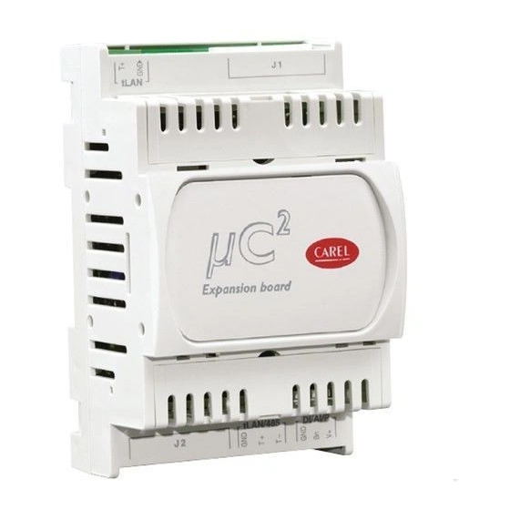
Page 71: Scheda Espansione Per
I/O Layout µC Description Expansion Description Control probe (Evaporator inlet/ambient) Sonda uscita in comune ai 2 evaporatori (solo con 2 circuiti) Protection probe (evaporator outlet/outlet) Sonda di protezione (uscita 2° evaporatore) circuito 2 Condenser/outside temperature probe Sonda di temperatura 2° condensatore B4 (universal) Condenser pressure probe B8 (universal) -
Page 72: Evd*: Driver Per La Valvola Di Espansione Elettronica
NOTE: L’espansione è dotata di due LED, posti sulla scheda base (per NOTE: The expansion features two LEDs on the main board (to see la visione togliere lo sportello superiore o inferiore), con i quali rende these, remove the top or bottom door), which display its status by the following messages: visibile il suo stato mediante i seguenti messaggi: Acceso... -
Page 73: Scheda Gestione Velocità Ventilatori (Cod. Mchrtf*)
7.4 Scheda gestione velocità ventilatori (cod. MCHRTF*) 7.4 Fan speed control board (code MCHRTF*) Le schede tagli di fase con codice MCHRTF**** permettono il controllo The phase cutting boards (code MCHRTF****) are used to control the della velocità di rotazione dei ventilatori di condensazione. speed of the condenser fans. -
Page 74: Calcolo Della Velocità Minima E Massima Dei Ventilatori
To make identification of the sempre permessa. Per facilitare l’indivi- duazione della chiave da utilizzarsi, key easier CAREL has inserted a label CAREL ha inserito un’etichetta su cui si on which you can describe the loaded può descrivere la programmazione caricata programming or the machine to which you are referring. - Page 75 UPLOAD - copia dei parametri da uno strumento verso la chiave: UPLOAD - copying the parameters from an instrument to the key: • aprire lo sportellino posteriore della chiave e posizionare i due • open the rear hatch of the key and place the two dip-switches in the OFF position (see Fig.
-
Page 76: Opzione Seriale Rs485
Caratteristiche tecniche: Alimentazione PSOPZKEY00 - Utilizzare tre batterie 1,5 V 190 mA (D357H Duracell o equivalenti) - Corrente massima fornita 50 mA max. Alimentazione PSOPZKEYA0 - Alimentatore switching: Input 100...240 V~; (-10%, +10%); 50/60 Hz; 90 mA. Output: 5 Vdc; 650 mA Condizioni di funzionamento 0T50°C U.R. -
Page 77: Remote Terminal For Μc
7.10 Terminale remoto µC 7.10 Remote terminal for µC Il terminale remoto per µC (MCH200TP* versione a pannello e The remote terminal for µC (MCH200TP* panel version and MCH200TW* MCH200TW* versione a parete) è un dispositivo elettronico che permette wall-mounting version), is an electronic device that allows the remote il controllo a distanza di una unità... - Page 78 Collegamenti elettrici (Fig. 7.10.2-7.10.3) Electrical connections (Fig. 7.10.2-7.10.3) Collegare la linea seriale RS485 in uscita dall’alimentatore “RJ12 Connect the RS485 serial line leaving the power supply “RJ12 Power supply” to the supervisor input on the µC , using a twisted pair cable Power supply”...
- Page 79 Schema di collegamento (alimentazione remotata)/ Connection diagram (remote power supply) MCH200001* FCSER00000 MCH200TW* in alternativa MCH200TP* alternative : MCH200000* MCH2004850 (vedi Fig. 7.10.2) (see Fig. 7.10.2) L. max.= 40 m Cavo telefonico Max. l.= 40 m Telephone cable Inserire resistenza di RJ12 terminazione da 120 ohm tra Power supply...
- Page 80 Informazioni visualizzate (Fig 7.10.7): Information displayed (Fig 7.10.7): Riga display Significato Display row Meaning Versione firmware terminale Terminal firmware version Versione firmware µC µC firmware version Indirizzo supervisore del µC Supervisor address of the µC Tasso di errore percentuale relativo alla comunicaz. tra term. e µC Percentage error rate in the communic.
- Page 81 Funzione associata ai tasti/ Functions associated with the buttons Tasto Stato della macchina Modalità pressione Button Unit status Button operation Spegne buzzer o relè allarme, se allarme attivo Pressione singola Switch off buzzer or alarm relay, if alarm active Press once Forza rientro manuale allarmi non più...
-
Page 82: Dimensions
Caratteristiche Tecniche alimentatore “RJ12 Power supply” Technical specifications of the power supply “RJ12 Power supply” Tensione 24 Vac +10/–15% class 2 Corrente assorbita a 24 Vac 100 mA Fusibile esterno obbligatorio 250 mAT Trasformatore 3 VA (di sicurezza) Morsetto alimentazione estraibile a vite passo 5 mm;... - Page 83 MCH200000* µC versione da pannello MCH200001* µC versione guida din MCH200000* µC panel mounting version MCH200001* µC din-rail mounting version dima di foratura drilling template com p 71x29mm x10 0 montaggio a pannello montaggio su guida din fissaggio/ overall dimensions 91.5x36.5mm panel mounting din rail mounting Fig.
-
Page 84: Codes
Moduli regolazione ventilatori di Condenser fan control modules condensazione The four holes for fastening the speed control board have a I quattro fori di fissaggio della diameter of 4 mm, and the centre scheda regolazione velocità sono is positioned 3.5 mm from the di diametro 4 mm e il relativo edges of the board. -
Page 85: Technical Specifications
NTC CAREL (10 kΩ a 25 °C) Il tempo di risposta dipende dal componente utilizzato, valore tipico 90 s B4: Sonde di temp. NTC (10 kΩ a 25 °C) o sonde di pressione raziom. CAREL 0...5 V SPK*00**R* Uscita fan Segnale di commando per moduli CAREL MCHRTF****, CONVONOFF* e CONV0/10A* Modulazione di posizione d’impulso (con larghezza impostabile) o modulazione del duty-cicle... - Page 86 B1, B2, B3, B4: NTC CAREL temperature probes (10 k Ω at 25 °C) The response time depends on the component used, typical value 90 s B4: NTC temp. probes (10 k Ω at 25 °C) or CAREL 0 to 5 V ratiometric pressure probes SPKT00**R* Fan output...
-
Page 87: Software Updates
Caratteristiche dei connettori Characteristics of the connectors I connettori possono essere acquistati con il codice CAREL The connectors may be purchased using CAREL code (MCHCON0***) or from the manufacturer Molex (MCHCON0***) o dal costruttore Molex ® ® Codice Molex ®... - Page 88 Agenzia/Agency: CAREL S.p.A. Via dell’Industria, 11 - 35020 Brugine - Padova (Italy) Tel. (+39) 049.9716611 - Fax (+39) 049.9716600 e-mail: carel@carel.com - www.carel.com...
Need help?
Do you have a question about the µC2 and is the answer not in the manual?
Questions and answers