
Related Manuals for Carel uChiller UCHBP000X0200


Summarization of Contents
General Safety and Disposal Information
General Warnings
Avoid installing the controller in environments with unsuitable temperature, humidity, or exposure to contaminants.
Disposal of WEEE
Information on correct handling and disposal of waste electrical and electronic equipment (WEEE).
Important Cable Separation Notice
Separate probe and digital input cables from power cables to avoid electromagnetic disturbance.
Introduction to the CAREL μChiller
Main Functions Overview
Details the primary functions and capabilities of the μChiller system.
μChiller Models and Accessories
Available Models
Overview of available μChiller controller models and their configurations.
System Accessories
Details on optional accessories for user terminals, drivers, and connectivity.
Temperature and Pressure Sensors
Specifications for temperature and pressure sensors used in the system.
Expansion Valves and Modules
Details on unipolar valves, ultracap modules, and tERA connectivity.
Connector Kits and Converters
Information on connector kits, display cables, and USB/RS485 converters.
Installation Guide for the μChiller
Installation Warnings
Crucial warnings regarding environmental conditions and installation practices.
Panel Mounting Installation
Details on panel version dimensions, assembly, and removal.
DIN Rail Mounting Installation
Details on DIN rail version dimensions, assembly, and removal.
Electrical Installation and Wiring
Essential guidelines for safe and correct electrical wiring and connections.
Terminal Description and Probe Connections
Detailed breakdown of terminal assignments and probe connection diagrams.
User Terminal Connections
Wiring diagrams for connecting user terminals and PGDx displays.
Internal Panel Positioning
Best practices for controller placement within electrical cabinets for optimal performance.
Serial Port Connections
Instructions for serial communication setup between two circuits using FBus and BMS ports.
Power+ Speed Drive Connection
Wiring and configuration for connecting Power+ speed drive to BLDC compressors.
Probe and Component Positioning
Diagrams illustrating optimal placement of probes and components on units.
Input/Output Configuration
Configuration of analogue and digital inputs/outputs for mCH2 and mCH2 SE replacement.
Functional Diagrams for Chillers
Diagrams showing electrical and serial connections for chillers with On/Off compressors.
Functional Diagrams for Free Cooling Systems
Connection diagrams for chillers with free cooling and thermostatic expansion valve.
Functional Diagrams for Heat Pumps
Connection diagrams for chillers/heat pumps with On/Off compressors and bipolar ExV valve.
Functional Diagrams for Water-to-Water Systems
Connection diagrams for chiller/heat pump with On/Off compressors and bipolar ExV valve.
Functional Diagrams with Unipolar ExV Valve
Connection diagrams for chillers with On/Off compressors and unipolar ExV valve.
Functional Diagrams with BLDC+On/Off Compressors
Connection diagrams for chillers/heat pumps with BLDC+On/Off compressors and bipolar ExV valve.
Functional Diagrams with BLDC+On/Off Compressors (Revised)
Connection diagrams for chillers/heat pumps with BLDC+On/Off compressors and bipolar ExV valve.
Initial Configuration of the μChiller
Configuring with the APPLICA App
Using the APPLICA mobile app for unit configuration via NFC or Bluetooth.
Configuration Procedure Steps
Step-by-step guide for configuring refrigerant and BLDC compressor settings via APPLICA.
Unit and IO Configuration
Configuring unit parameters and inputs/outputs using the APPLICA app.
mCH2 and Date/Time Settings
Setting mCH2 parameters and synchronizing unit date/time using APPLICA.
Parameter Lists and Configuration
Comprehensive lists of unit setup and I/O configuration parameters.
mCH2 Parameters and Applica Desktop
Specific mCH2 parameters and using APPLICA Desktop for unit configuration.
Operation Preparation with Applica Desktop
Steps for preparing the unit for operation using Applica Desktop, including connection.
μChiller Configuration via Applica Desktop
Configuring unit parameters and I/O settings via Applica Desktop and applying changes.
Date and Time Setting with Applica Desktop
Setting unit date and time via PC synchronization using Applica Desktop.
Understanding the μChiller User Interface
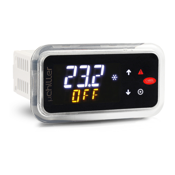
User Interface Introduction
Overview of the user terminal's display, controls, and connectivity features.
User Terminal Components
Description of the user terminal components: keypad, display field, and status icons.
Keypad Functions
Explanation of keypad buttons and their functions for navigation and control.
Device Status Icons
Table of icons representing device status and operating modes.
Standard Display Information
Description of the standard display showing unit status and key temperatures.
Dashboard and Direct Access Functions
Accessing device status via Dashboard and basic functions directly.
Programming Mode Operations
Procedure for accessing and modifying parameters through programming mode with password protection.
Programming Menu Categories
Description of programming menu categories and navigation methods.
μChiller Controller Functions
Temperature Control with PID
Managing unit temperature control using PID algorithms for precise regulation.
Proportional Control
Using proportional control for water temperature regulation based on specific relationships.
Setpoint Compensation
Adjusting set points based on outside temperature for optimized cooling and heating.
BMS Request Integration
Integrating the controller with a BMS for external control requests via Modbus.
High Evaporator Outlet Temperature Alarm
Managing high evaporator outlet temperature alarms for unit protection.
User Pump Management
Configuration and management of user-side pumps, including activation delays and safety features.
Cyclical Pump Activation During Standby
Implementing cyclical pump activation during standby for energy saving.
Frost Protection Control Strategies
Implementing frost protection to prevent damage from ice formation on evaporator coils.
Frost Protection Alarm Management
Managing frost protection alarms, unit shutdown, and automatic reset procedures.
Frost Protection Threshold with Glide (R407C)
Setting frost protection thresholds considering refrigerants with glide effects.
Frost Protection Alarm with Water Temperature
Using water temperature for frost protection alarms in cooling and heating modes.
Frost Prevention Methods
Methods for frost prevention by limiting capacity and activating heaters.
Frost Protection Management with Two Circuits
Frost protection control strategies for single and dual-circuit units.
Frost Protection When Unit is OFF
Ensuring frost protection when the unit is off via pump or heater activation.
Compressor Rotation Management
Balancing compressor usage in multi-compressor systems for longevity and efficiency.
Compressor Rotation Types
Understanding FIFO and time-based rotation logic for compressor operation.
Alarm-Based Compressor Rotation
Automatic compressor switching in case of alarm to maintain system operation.
Forced Compressor Rotation (Destabilisation)
Using forced rotation to prevent issues like refrigerant migration during idle periods.
Compressor Management
Comprehensive management of scroll and BLDC compressors, including start-up and safety features.
Predefined BLDC Compressors
Selecting and configuring BLDC compressors based on manufacturer data.
Compressor Safety Times
Ensuring compressor longevity by adhering to critical safety time parameters.
BLDC Compressor Start-up Procedure
Managing BLDC compressor start-up sequence according to manufacturer specifications.
BLDC Oil Recovery Function
Implementing oil recovery procedures to maintain lubrication in BLDC compressors.
Tandem BLDC Oil Equalisation
Oil equalization process for tandem BLDC compressors to ensure proper lubrication.
Capacity Control for Legacy Compressors
Capacity control strategies for Legacy models with multiple compressors.
BLDC Compressor Protectors
Protecting BLDC compressors by enforcing operating limits and safety envelopes.
BLDC Compressor Alarm Prevention
Actions to prevent BLDC compressor alarms by maintaining operation within envelope limits.
Prevention Actions for BLDC Compressors
Detailed explanation of prevention actions for BLDC compressors based on operating zones.
High Compression Ratio Prevention
Managing high compression ratio to prevent compressor damage and maintain safe operation.
High Condensing Pressure Prevention
Preventing operation issues related to high condensing pressure through capacity adjustments.
High Motor Current Prevention
Protecting against high motor current by adjusting compressor capacity or limiting operation.
High Evaporation Pressure Prevention
Preventing operation outside limits due to high evaporation pressure by reducing capacity.
Low Compression Ratio Prevention
Ensuring operation within limits by managing low compression ratio conditions.
Low Differential Pressure Prevention
Preventing operation outside limits due to low differential pressure through capacity adjustments.
Low Condensing Pressure Prevention
Preventing operation outside limits due to low condensing pressure by adjusting capacity.
Compressor Alarms
Handling compressor alarms to prevent damage and ensure system reliability.
Power+ Speed Drive Integration
Controlling BLDC compressors using the Power+ Speed Drive.
Expansion Valve Driver Functionality
Managing electronic expansion valves for precise control of refrigerant flow and compressor operation.
Expansion Valve Control Logic
Controlling the expansion valve for superheat, evaporation temperature, and cooling capacity.
Source Pump Operation
Managing the source pump for water/water units, including activation and frost protection.
Source Fan Control
Controlling source fans for condenser operation in various configurations.
Modulating and On-Off Fan Control
Configuring modulating and ON-OFF fan control modes and parameters.
Fan Control in Chiller Mode
Fan control strategies for chiller mode, based on condensing temperature.
Fan Control in Heat Pump Mode
Fan control strategies for heat pump mode, based on evaporation pressure.
Low Noise Fan Functionality
Reducing fan noise during specific periods by adjusting set points and speed.
Fan Anti-Blocking Function
Preventing frost formation in cold climates by maintaining minimum fan speed.
Free Cooling Functionality
Enabling and configuring free cooling functions for chiller units.
Types of Free Cooling
Overview of different free cooling types and their configurations.
Condensing Unit with Common Air Circuit
Free cooling configuration for condensing units with a shared air circuit.
Air-Cooled Condensing Unit with Separate Air Circuit
Free cooling configuration for air-cooled units with separate air circuits.
Water-Cooled Condensing Unit
Free cooling configuration for water-cooled condensing units.
Dynamic Control Gain for Free Cooling
Adjusting control gain for balancing free cooling and evaporator capacity.
Effectiveness Control in Free Cooling
Managing unit operation when free cooling is insufficient, potentially engaging compressors.
Valve Anti-Block Management
Preventing valve mechanical blockage through periodic movement.
Defrost Cycle Management
Managing the defrost cycle to remove frost and restore unit efficiency.
Defrost Procedure Details
Detailed steps and phases involved in the defrost cycle.
Defrost Phase Synchronization
Synchronizing defrost operations between multiple circuits for optimal performance.
Capacity Reduction During Defrost Start
Reducing compressor capacity during the initial phase of defrosting.
Waiting Time Before Cycle Reversal
Delay period after cycle reversal to ensure correct refrigerant flow.
Cycle Reversal and Waiting Time
Steps involved in cycle reversal and subsequent waiting periods for defrost.
Defrosting Phase Details
The main defrost phase where ice is melted by fan action.
Dripping Phase Management (Compressor ON)
Managing fan speed during dripping phase with compressor ON.
Capacity Reduction to End Defrost
Reducing capacity and reversing cycle to conclude defrost based on pressure difference.
Waiting After Cycle Reversal (Compressor ON)
Waiting period after cycle reversal to ensure proper refrigerant flow.
Dripping Phase Management (Compressor OFF)
Managing dripping phase with compressor OFF, waiting for coil to complete defrosting.
Post-Dripping Phase (Compressor OFF)
Expelling residual water after dripping phase using fans at maximum speed.
Quick Start Phase (Compressor OFF)
Rapid compressor restart after a short off period to quickly achieve operational speed.
Defrosting with Fans
Using fans for defrosting in mild conditions to improve energy efficiency.
Sliding Defrost Functionality
Adjusting defrost delay based on outside air temperature to account for ice formation.
Defrost Synchronization Options
Synchronizing defrost procedures for multi-circuit units for independent or simultaneous defrost.
4-Way Valve Management
Ensuring correct operation of the 4-way valve by checking pressure differential.
Manual Device Management
Manually controlling actuators for testing and verification purposes.
Air/Air Unit Management (Legacy)
Managing air/air units, including cooling/reverse cycle and specific control probes.
User Fan Control on Air/Air Units
Controlling the user fan on air/air units, including activation modes and hot-start/hot-keep functions.
Hot-Start and Hot-Keep Functions
Functions to manage fan behavior during heating for air/air units.
Compressor Deactivation by Temperature
Deactivating compressors at low outdoor temperatures to save energy.
Heater Management for Air/Air Units
Controlling electric heaters for air-air units, including defrost activation and offset settings.
Automatic Heater Management for Water Units (Legacy)
Managing auxiliary heaters for water units in heating mode for automatic control.
Condensing Unit Management
Managing condensing units with one or two circuits, and different cooling modes.
Automatic Changeover (Legacy Model)
Automatic switching between cooling and heating modes based on temperature for Legacy models.
Automatic Changeover Modes
Automatic changeover logic based on outside air, air return, or delivery water temperature.
μChiller Parameter Reference
System Parameters
Parameters related to system settings, including pump, set points, and time bands.
Compressor Parameters
Parameters for compressor maintenance, operating modes, and circuit configurations.
BLDC and Inverter Parameters
Parameters specific to BLDC compressors and inverter control, including limits and oil management.
Expansion Valve Parameters
Parameters governing the operation of expansion valves, including superheat and pressure controls.
Source Parameters
Parameters for controlling source pumps and fans, including operating modes and speed settings.
Input/Output Configuration Parameters
Parameters for configuring all analogue and digital inputs and outputs.
mCH2 Parameters (Legacy Models)
Specific parameters for mCH2 compatibility in Legacy models.
BMS Port Configuration
Configuration settings for BMS communication via the serial port.
Password Settings
Password settings for different access levels (User, Service, Manufacturer).
Dashboard Monitoring Values
List of parameters available on the dashboard for monitoring unit status.
General Controller Settings
General controller settings, including set points, modes, and alarm reset configurations.
Supervisor Table Reference
Coil Status Variables
Supervisor variables indicating the status of coils, pumps, fans, and valves.
Input Status Variables
Supervisor variables reflecting the status of inputs, including probe and switch conditions.
Holding Register Variables
Holding register list for supervisor variables, covering maintenance hours, modes, and set points.
Alarms and Signals Management
Types of Alarms
Classification of alarms by reset mode and identification of configurable alarms.
Active Alarms Acknowledgement
Procedure for acknowledging and navigating active alarms displayed on the terminal.
Comprehensive Alarm List
Detailed list of all possible alarms, their codes, effects, and reset modes.
Technical Specifications of the μChiller
Physical Specifications
Physical characteristics: dimensions, case material, assembly, and ingress protection.
Environmental Conditions
Operating and storage environmental requirements for the controller.
Electrical Specifications
Electrical details: power supply, current, clock precision, and protection class.
User Interface Specifications
Specifications for the user interface components and capabilities.
Connectivity Interface Specifications
Technical details of communication interfaces: NFC, Bluetooth, BMS, FieldBUS, HMI.
Analogue Input Specifications
Specifications for analogue input channels and supported sensor types.
Digital Input Specifications
Specifications for digital input channels and their characteristics.
Valve Output Specifications
Specifications for the unipolar ExV valve power supply.
Analogue and Digital Output Specifications
Specifications for analogue and digital output signals and relays.
Emergency Power Supply and Probe Power
Details on Ultracap module and power supplies for probes and terminals.
Serial Port and Cable Length Specifications
Specifications for BMS and FieldBus serial ports and recommended cable lengths.
Conformity Standards
Compliance standards for electrical safety, EMC, and refrigerant gases.
Connector and Cable Table
Reference table for connectors and cables used with the controller.
Need help?
Do you have a question about the uChiller UCHBP000X0200 and is the answer not in the manual?
Questions and answers