
Related Manuals for Carel uChiller UCHBP000X0190


Summary of Contents for Carel uChiller UCHBP000X0190
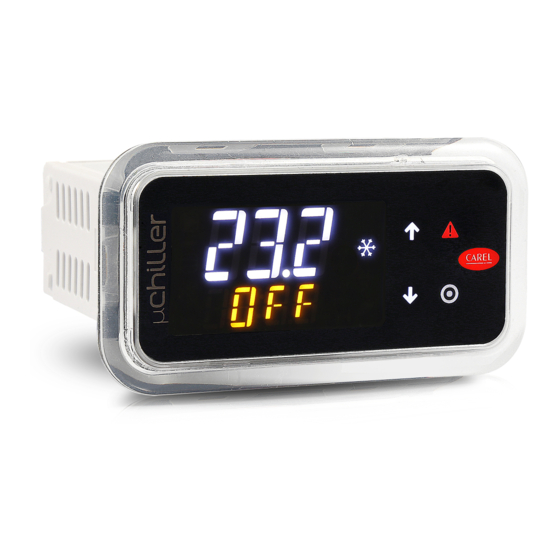
- Page 1 μChiller Controller for Chiller / Heat Pump USER MANUAL NO POWER & SIGNAL CABLES TOGETHER READ CAREFULLY IN THE TEXT! μChiller +0300053EN - ENG Up to date version available on www.carel.com...
- Page 3 fi cations shown in the manual may be changed without prior warning. plication of the various product functions. The liability of CAREL in relation to its products is specifi ed in the CAREL general contract conditions, available on the website www.carel.com and/ Important: This product is to be integrated and/or incorporated into the or by specifi...
- Page 5 Index 1. Introduction ............... 7 6. Parameter table ............83 1.1 Main functions ....................7 6.1 System ........................83 1.2 Models ........................8 6.2 Compressor ....................... 84 1.3 Accessories ......................8 6.3 BLDC and Inverter ..................85 6.4 Valve ........................86 2. Installation ............... 12 6.5 Source ........................
- Page 7 The user terminal allows wireless connectivity with mobile devices and is built- in on the panel mounted models, or sold separately on DIN rail mounted models. CAREL’s “APPLICA” app, available on Google Play for the Android operating system, makes it easier to confi...
- Page 8 1.3.3 EVD Evolution/EVD Evolution twin valve driver The Enhanced and High Effi ciency models have the driver built-into the controller, able to drive unipolar valves (up to Carel model E3V, with a cooling capacity less than 90-100kW); all versions can be connected to the external EVD Evolution driver to drive bipolar valves (with a higher cooling capacity).
- Page 9 EVD evolution twin universal, (RS485/Modbus) multiple pack of 10 pcs. EVD0000T50 EVD evolution twin Carel valve (RS485/Modbus) EVD0000T51 EVD evolution twin Carel valve, (RS485/Modbus) multiple pack of 10 pcs. Fig. 1.c Tab. 1.e 1.3.4 Temperature sensors NTC sensors for measuring the temperatures in the user circuit, the outdoor air or source, and the refrigeration circuit. NTC**HT sensors are recommended for discharge temperature measurement (with BLDC compressors in heat pump mode).
- Page 10 Fig. 1.h 1.3.9 Couldgate for tERA connection CloudGate is CAREL’s new family of IoT gateways to enable monitoring and tERA plat- form services for HVAC/R systems with up to 10 units. Compact, standard installation inside an electrical panel and a local LED interface with immediate indication of communication status make Cloudgate easy to install in the fi...
- Page 11 1.3.10 Connector kit Part number Description UCHCONP000 uChiller panel MOLEX/free connector kit UCHCONP010 uChiller panel MOLEX/free connector and 100 cm cable kit UCHCONP030 uChiller panel Molex/free connector and 300 cm cable kit UCHCOND000 uChiller DIN MOLEX/free connector kit UCHCOND010 uChiller DIN MOLEX/free connector and 100 cm cable kit UCHCONPMC0 Adapter kit for MCH2 Fig.
- Page 12 2. INSTALLATION Warnings Important: avoid installing the controller in environments with the following characteristics: • temperature and humidity that do not comply with the ambient operating conditions (see “Technical specifi cations”); • strong vibrations or knocks; • exposure to water sprays or condensate; •...
- Page 13 2.2.3 Removal Open the electrical panel from the rear and press the anchor- ing tabs and then the controller to remove it. 1. Gently press the side anchoring tabs on the controller; 2. Exert slight pressure on the controller until it is removed. Important: the operation does not require the use of a screwdriver or other tools.
-
Page 14: Table Of Contents
BMS serial port (RS485): Rx/Tx- Digital output (relay) 6 BMS serial port (RS485): Rx/Tx+ J14* Carel ExV unipolar valve connector BMS serial port (RS485): GND Tab. 2.a (*) for DIN Enhanced / High Effi ciency models only Probe/digital input connection... - Page 15 For the position of the sensor on the suction pipe, see the installation guide +040010025 ““Sonde e sensori - Guida alla scelta e all’installazione ottimale / Probes and sensors - Selection and optimal installation guide”, available at carel.com under product => sensor => quick guide. Connection to user terminals 2.6.1 Panel model...
- Page 16 Connection to connector J4 G0 G S6 +V S1 S3 5V J4 BMS J5 FBus J4 BMS PGDx + – Tx/Rx+ Tx/Rx- shield 24 Vdc PGTA00TRX0 230 Vac Fig. 2.m Connection to connector J8 G0 G C NO6 PGDx S6 +V S1 S3 5V J5 FBus J4 BMS...
- Page 17 Electrical installation Important: When laying the wiring, “physically” separate the power part from the control part. The proximity of these two sets of wires will, in most cases, cause problems of induced disturbance or, over time, malfunctions or damage to the compo- nents.
- Page 18 2.10 Connection to Power+ (for BLDC) For the serial connection between the controller and the Power+ speed drive, see the specifi c manual. Also see the following diagrams. G0 G power+ speed drive evolution J5 FBus J4 BMS S6 +V S1 S3 5V shield shield...
-
Page 19: Din Rail Model Basic
2.11 Positioning of probes/ components Water-cooled unit Air-cooled unit Fig. 2.r Fig. 2.s Ref. Description Ref. Description Source User pump User Source pump Evaporator Evaporation pressure probe Filter-drier Discharge temperature Liquid receiver Suction temperature Compressor High pressure switch Condenser Outside air temperature Liquid sightglass User pump fl... -
Page 20: Analogue Input
2.12.1 Analogue inputs The analogue inputs on μChiller Legacy are divided into four groups, according to the type of sensor connected. The groups and the list of parameters used to confi gure the diff erent analogue inputs are shown below: Group Sensor Slave confi g. -
Page 21: Analogue Output
The digital input confi guration parameters can have the following meaning: Slave description (circuit 2) Value Master description (circuit 1) Not used Not used User pump fl ow switch User pump fl ow switch Comp. 1 thermal protector circ. 1 Comp. -
Page 22: Id2 Y2 S2 S5
2.13 Functional diagrams 2.13.1 Chillers, On/Off compressors and thermostatic expansion valve Important: The black lines refer to the electrical connections, the grey lines the serial connections between controller and options (I/O expansion for the second circuit, EVD EVO and Power+). Circuit 1 G0 G AL1_C1... - Page 23 Analogue inputs - Master circuit 1 Confi guration parameters Ref. Description Type Return temperature from user Hc31 Delivery temperature to user Hc32 Not present Hc00 Condensing pressure 0-5V Hc34; C040; C041; C042 Evaporation pressure 0-5V Hc35; C037; C038; C039 Not present Hc03;...
- Page 24 2.13.2 Chillers, On/Off compressors with free cooling and thermostatic expansion valve Important: The black lines refer to the electrical connections, the grey lines the serial connections between controller and options (I/O expansion for the second circuit, EVD EVO and Power+). Circuit 1 G0 G AL1_C1...
- Page 25 Analogue inputs - Master circuit 1 Confi guration parameters Ref. Description Type Return temperature from user Hc31 Delivery temperature to user Hc32 Not present Hc00 Condensing pressure 0-5V Hc34; C040; C041; C042 Evaporation pressure 0-5V Hc35; C037; C038; C039 Not present Hc03;...
-
Page 26: S6 +Vid5 Id3
2.13.3 Chillers/heat pumps, On/Off compressors and bipolar ExV expansion valve Important: The black lines refer to the electrical connections, the grey lines the serial connections between controller and options (I/O expansion for the second circuit, EVD EVO and Power+). Circuit 1 G0 G 2_Set AL1_C1... - Page 27 Analogue inputs - Master circuit 1 Confi guration parameters Ref. Description Type Return temperature from user Hc31 Delivery temperature to user Hc32 Not present Hc00 Condensing pressure 0-5V Hc34; C040; 041; C042 Evaporation pressure 0-5V Hc35; C037; C038; C039 Not present Hc03;...
- Page 28 2.13.4 Chiller/water-to-water heat pump, On/Off compressors and bipolar ExV expan- sion valve Important: The black lines refer to the electrical connections, the grey lines the serial connections between controller and options (I/O expansion for the second circuit, EVD EVO and Power+). Circuit 1 Circuit 2 Fig.
- Page 29 Analogue inputs - Master circuit 1 Confi guration parameters Ref. Description Type Return temperature from user Hc31 Delivery temperature to user Hc32 Source water delivery temperature Hc00 Condensing pressure 0-5V Hc34; C040; C041; C042 Evaporation pressure 0-5V Hc35; C037; C038; C039 Not present Hc03;...
- Page 30 2.13.5 Chillers, On/Off compressors and unipolar ExV expansion valve Important: The black lines refer to the electrical connections, the grey lines the serial connections between controller and options (I/O expansion for the second circuit, EVD EVO and Power+). Circuit 1 G0 G AL1_C1 2_Set...
- Page 31 Analogue inputs - Master circuit 1 Confi guration parameters Ref. Description Type Return temperature from user Hc31 Delivery temperature to user Hc32 Not present Hc00 Condensing pressure 0-5V Hc34; C040; 041; C042 Evaporation pressure 0-5V Hc35; C037; C038; C039 Not present Hc03;...
- Page 32 2.13.6 Chillers/heat pumps, BLDC+On/Off compressors and bipolar ExV expansion valve Important: The black lines refer to the electrical connections, the grey lines the serial connections between controller and options (I/O expansion for the second circuit, EVD EVO and Power+). Circuit 1 G0 G AL1_C1 2_Set...
- Page 33 Analogue inputs - Master circuit 1 Confi guration parameters Ref. Description Type Return temperature from user Hc31 Delivery temperature to user Hc32 Discharge temperature Hc00 Condensing pressure 0-5V Hc34; C040; 041; C042 Evaporation pressure 0-5V Hc35; C037; C038; C039 Not present Hc03;...
- Page 34 2.13.7 Chillers/heat pumps, BLDC+On/Off compressors and bipolar ExV expansion valve Important: The black lines refer to the electrical connections, the grey lines the serial connections between controller and options (I/O expansion for the second circuit, EVD EVO and Power+). G0 G 2_Set J5 FBus J4 BMS...
- Page 35 Analogue inputs Confi guration parameters Ref. Description Type Return temperature from user Hc31 Delivery temperature to user -Hc32 Discharge temperature Hc00 Condensing pressure 0-5V Hc34; C040; 041; C042 Evaporation pressure 0-5V Hc35; C037; C038; C039 Not present Hc03; U025; U026; U027 Suction temperature Hc04 Tab.
- Page 36 (recipes). Once the Carel “Applica” app has been installed and opened (see the paragraph “Mobile device”, proceed as follows: 1. For NFC devices, move (A) the mobile device near to the μChiller user terminal (the position of the NFC antenna on the mobile device must be identifi...
- Page 37 4. apply the selected confi guration via NFC or Bluetooth. The refrigerant has now been correctly confi gured. High Effi ciency model 1. With Bluetooth devices, access the Service menu by clicking the icon at the bottom right (fi gure). With NFC devices, the Service menu is already displayed by default (fi...
- Page 38 3.2.2 Step 2 - Confi gure the unit 1. continue confi guring the unit by clicking the “Set-up”--> “Unit setup” --> “Unit confi guration”. Complete the unit confi gura- tion by pressing the PREV / NEXT buttons to scroll through all of the confi guration parameter pages; 2.
- Page 39 3.2.4 Step 4 - Confi gure parameter compatibility with mCH2 (Legacy model only) 1. click “Set-up”--> “Unit setup” --> “mCH2 parameters” and complete the confi guration of the unit 2. apply the parameters confi gured via NFC / Bluetooth to the controller. 3.2.5 Applica: date and time setting Applica includes a feature for setting the date and time on μChiller in just one simple step, copying the values from the mobile device.
- Page 40 Notice: with a Bluetooth connection the confi guration is saved/applied on confi rmation. With reference to the previous fi gure, tapping the icon: 1. accesses the confi gurations saved by the user; 2. accesses the confi gurations prepared by Carel; 3. accesses the saved clones. Unit set-up parameter list 3.3.1 Unit parameters...
- Page 41 Par. Description Def. Min. Max. U071 Design free cooling delta T 99.9 U061 System pump overload: input logic (0/1=NC/NO) U065 Freecooling valve: output logic (0/1=NO/NC) S063 Reversing valve: output logic (0/1=NO/NC) S054 4-way valve: pressure diff erential for reversing 999.9 C049 Low pressure switch alarm delay on compressor activation C050...
- Page 42 Applica Desktop Applica Desktop is a program intended for manufacturers and installers of units fi tted with the μChiller controller. It can be downloaded from ksa.carel.com. The Applica Desktop off ers the possibility to: • access the controller using the assigned profi le;...
- Page 43 3.4.1 Preparing for operation 1. Access KSA, “Software & Support”, ” μChiller” section. 2. Select the “Confi gurations” folder. 3. For μChiller Standard, Enhanced and Legacy models (with On/Off compressor), select the “Refrigerants” section and then the refrigerant charged on the unit. 4.
- Page 44 3.5.2 Step 2 - Confi gure μChiller 1. Select the “Confi gurations” label, select “New -> New confi guration” and assign a name to the new confi guration being created. 2. Select the newly created confi guration 3. Select “Edit -> Apply Live Values”. This operation copies the values of the parameters currently saved on the connected μChiller to the newly created confi...
- Page 45 Finally, to save the newly-created confi guration for future use, from the “Confi gurations” label select “File -> Export” and assign a name to the confi guration being saved. 3.5.3 Applica Desktop: date and time setting Applica Desktop can set the date and time on μChiller in just one simple step, copying the values from the PC to the controller. Procedure: 1.
- Page 46 4 buttons for scrolling and setting the parameters. The terminal has NFC (Near Field Communication) and Bluetooth (depending on the model) connectivity for interaction with mobile devices (on which the Carel “Applica” app has been installed, available on Google Play for the Android operating system).
- Page 47 4.2.2 Icons The icons indicate the device operating status and operating modes, as shown in the following table. Icon Function Flashing System pump Active In manual operation Source device status (pump/fan) Active In manual operation Compressor status Active In manual operation (with ExV) Frost protection heater Active Operating mode...
- Page 48 Example Go to the standard display. Press DOWN: CMP indicates that com- Press DOWN: EuP1 indicates the pressor 1 is on (o) and compressor 2 evaporation temperature in circuit 1 is off (_). (3.8°C). Press DOWN: Cnd1 indicates the To return to the standard display, press condensing temperature in circuit 1 PRG (corresponding to ESC).
- Page 49 7. Press DOWN: the function for swi- 8. Press DOWN: the manual defrost 9. Press DOWN: the function to dele- tching from cooling (C) to heating function (dFr) is shown - Service te the alarm log (ClrH) is shown (H) mode (ModE) is shown - for level and reverse-cycle A/W units –...
- Page 50 4.3.4 Programming menu Category PLt (system): identifi ed by Category EEV (ExV valve): identifi ed by Category CMP (compressors): identi- code Uxxx, these parameters all relate code Exxx, these parameters all relate fi ed by code Cxxx, these parameters to control and management of the to control and management of the all relate to control and management system units.
- Page 51 5. FUNCTIONS Temperature control μChiller can control either the unit’s return or delivery water temperature. The return (from user) and delivery (to user) water temperature probes can be installed on any of the channels. See the Installation chapter. 5.1.1 PID control Two types of PID control are available: •...
- Page 52 5.1.2 Proportional control If the desired control is only proportional to the water outlet or return temperature, consider the relationship: For example, to have a proportional band of 2K, set the value of Kp to 50. The following are the parameter settings required to control the return temperature: Cod.
- Page 53 5.1.4 Request from BMS The request can be managed directly from a BMS, bypassing normal temperature control and enabling the external request signal (0-100.0%) via the specifi c Modbus serial variable (BMS_PwrReq, HR 331). This operation is enabled via another serial variable (En_BMS_PwrReq, CS 22).
- Page 54 Below is a diagram that represents operation for the confi guration with one pump only: Unit ON Not OK Thermoregulation Pump ON Enable Delay Flow alarm delay from pump start Not OK Flow status check, Pump status Not OK Flow alarm possible compressor star up...
- Page 55 Frost protection control Two frost protection control modes are available: 1. using the evaporation pressure probe, which directly monitors the conditions of the evaporator 2. using the water temperature probe to monitor the delivery water temperature or the source water temperature on water/ water units in heating mode).
- Page 56 Frost protection alarm operation: Thrs Countdown active t [s] Time [s] Thrsh Frost protection alarm threshold Frost protection alarm Countdown t (s) Fig. 5.i The value of the delay (at 1K) in the previous example refers to a plate evaporator; if a tube bundle evaporator is used, which has greater thermal inertia, the delay time (at 1K) can be increased to a suitable value.
- Page 57 5.3.4 Frost prevention The frost protection threshold on the evaporation temperature is used as the minimum evaporation temperature threshold for frost prevention. Prevention is applied by limiting circuit capacity when the threshold is exceeded and activating on the frost protection heater, if confi gured. For details on confi guring the frost protection heater, see the next paragraph, par 5.3.5 Notice: to ensure correct user-side frost protection, at least one probe - evaporation pressure/temperature or delivery water temperature - must be confi...
- Page 58 5.3.6 Frost protection with the unit OFF When the unit switched off , μChiller provides frost protection: the water is prevented form freezing by activating a pump and/or frost protection heater. When the water temperature in the heat exchangers reaches the frost protection set point, the selected device is activated.
- Page 59 100% Request FIFO Request Capacity request (temperature control) Compressor 1 Circuit 2 Compressor 2 Circuit 1 Fig. 5.k Capacity distribution with BLDC compressors If the circuit is equipped with a BLDC compressor, this will always be the fi rst to start and the last to stop. Circuit operation is modulated so as to meet the capacity request, adjusting BLDC compressor speed and controlling the activation of ON-OFF compressors.
- Page 60 5.5.1 Predefi ned BLDC compressors The type of BLDC compressor can be chosen from the list of compressors available on KSA (ksa.carel.com), μChiller section. When selecting a specifi c type of compressor, the following parameters are set based on the compressor manufacturer’s tech- nical specifi...
- Page 61 5.5.3 BLDC compressor start-up μChiller manages the start-up of BLDC compressors in accordance with the manufacturer’s specifi cations: on starting, the com- pressor is brought to start- up speed and kept at that speed, irrespective of the control request, for the entire minimum on time. At the end of this period, the speed is modulated by the controller, based on: •...
- Page 62 BLDC compressor protectors To prevent the compressor from working outside the safety limits specifi ed by the manufacturer, μChiller provides controls the operating limits (defi ned as the envelope) of BLDC compressors. In addition to the operating limits specifi ed by the manufactu- rer, the maximum condensing temperature (par.
-
Page 63: Bldc Compressor Start-Up
BLDC comp. alarm prevention The evaporation and condensation pressures determine a working point in a zone of the envelope, and depending on the zone, the controller applies corrective actions to maintain or return BLDC compressor operation within the limits. 5.7.1 Prevention actions for BLDC compressors Below is the description of the working zones in a generic envelope for BLDC compressors: Fig. - Page 64 High compression ratio prevention (zone 2) A high compression ratio is a thermal limit of compressor operation: normally control is activated at the limit of the envelope, reducing capacity when the limit is exceeded; if a probe is fi tted to measure discharge temperature (HP version only) and if the temperature approaches the limits, compressor capacity will be modulated so as to managed the critical condition.
-
Page 65: Def Min Max Uom
Low diff erential pressure prevention (zone 7) Device Description BLDC compressor 1. Decrease the rate of capacity reduction. 2. Increase capacity Tandem on-off compressors ExV valve Variable MOP Increase condensing pressure set point/decrease evaporation pressure setpoint Low condensing pressure prevention (zone 8) Device Description BLDC compressor... - Page 66 The solution provided manages unipolar valves up to a certain cooling capacity (Carel E3V - cooling capacity up to 90- 100 kW) with the built- in driver (DIN model only) and bipolar valves with higher capacities, using the external EVD Evolution driver.
-
Page 67: Min
On the μChiller panel version, analogue output Y1 is the only output available: consequently to control an on-off fan, a CONVO- NOFF module (Carel) is needed to convert the 0-10 V analogue output into a relay control. On the versions for DIN rail mounting, relay NO6 is available and can be confi... -
Page 68: Min
5.13.2 Control in chiller mode Fan control may be modulating or ON-OFF and is based on the saturated temperature value, equivalent to the condensing pressure, limited by Tc max. Code User Description C017 Max high pressure threshold (HP) 65.0 999.9 °C S028 Source fan in cooling: set point... - Page 69 The control diagram is shown below: Inverter 100% Max speed Max speed Modulating source fan: max speed value Min speed Modulating source fan: min speed value Control set point Min speed Control diff erential Tc max Maximum condensing temp. Evaporation temperature Te (°C) 1.5 K 2.5 K...
- Page 70 5.14 Free cooling The free cooling (FC) function can be enabled only on chiller units. The type of free cooling is confi gured by parameter, and may • air free cooling, on air/water units equipped with air- water heat exchanger coils upstream of the condenser coils and with modulating fan control;...
- Page 71 Ref. Description FC_E Free cooling heat exchanger Condenser FC_E Evaporator Filter-drier Liquid receiver Compressor Liquid sightglass FC_V Free cooling valve User pump User return probe User delivery probe Outside temperature probe FC_V Thermostatic expansion valve Solenoid valve Fig. 5.v 5.15.2 Air-cooled condensing unit with separate air circuit Free cooling is enabled based on the comparison between the user return water temperature and the outside air temperature;...
- Page 72 5.15.3 Water-cooled condensing unit Free cooling is enabled based on the comparison between the user return water temperature and the source water temperature (Temp. IN source); this controls modulation of the three-way valve that mixes the source water with the water returning from the user terminals through the free cooling coil before entering the evaporator.
- Page 73 5.16 Free cooling 5.16.1 Dynamic control gain This special function manages the balancing of capacity between the free cooling coil and the evaporator: this optimises control stability and fl uidity. Code User Description U070 Free cooling: hysteresis 99.9 U069 Free cooling: activation diff erential 99.9 U071 Design free cooling delta T...
- Page 74 5.17 Defrost During heat pump operation on air/water units, the outdoor coil works as an evaporator. If the outside temperature is low, frost may form on the coil, resulting in reduced unit effi ciency. To free the coil from frost and restore maximum effi ciency, μChiller activates the defrost function.
- Page 75 The control phases are described below. Synchronisation (1) Once the defrost start condition is true, there is a fi xed delay of 10 s to check whether the other circuit requires defrosting, so as to carry out a simultaneous defrost if needed. Code User Description...
- Page 76 Waiting after cycle reversal (case with comp. ON) (8) After reversing the cycle, there is a waiting time to ensure the correct fl ow of refrigerant; in this phase too, the ExV remains in the 100% open position. Code User Description S045 Operation time at min capacity after cycle reversing...
- Page 77 Synchronisation (1): See the previous defrosts. Compressor stopped to start defrosting (2) The circuit with the BLDC compressor decreases its capacity to the minimum set value, and then switches off ; on-off compres- sors are all switched off . Defrosting (5) The actual defrosting phase starts: the fans are started at 100% speed to heat the coil and melt the ice that has formed on the fi...
- Page 78 Separate When the fi rst circuit requires defrosting: • it starts the defrost procedure; • the other continues to work in heat pump mode. When the fi rst circuit has fi nished defrosting, the other is free to start. Simultaneous This procedure is used if the air fl...
- Page 79 5.20 Air/air unit management (Legacy model only) The μChiller Legacy version can manage air/air units, both cooling only and reverse cycle. The type of unit is selected via param- eter U077, which in the Legacy model can be set as Air/Air CH or Air/Air CH/HP. On these units, the control probes have the following meaning: Sensor Meaning...
- Page 80 5.20.2 Heater management on air-air units This function is only active when the unit is on - main fan on and control active or in defrost. The type of control is set using parameter F028: • room temperature (F028 = 0) •...
- Page 81 The auxiliary heater works mainly to supplement the main control, but also remains active for frost protection. In the event of frost protection, when both auxiliary and frost protection heaters are installed, both outputs will be active. Up to two heaters are available, however with the following confi guration required: •...
- Page 82 5.23.1 Mode 1: outside air temperature; Heat If automatic changeover is set based on the outside tempera- Cool ture, the main temperature control will use the probes confi g- ured for U036 (start-up) and Uo38 (running) and the set points SetC (cooling) and SetH (heating).
- Page 83 6. PARAMETER TABLE Notes: • Levels: U=User; S=Service; M=Manufacturer; Display: the x indicates that the parameter can be accessed from the display terminal; • R/W=read/write parameters; R=read-only parameters. System Code User Display Description Def. Min. Max. Modbus Plt = System U000 User pump 1: maintenance hour threshold (x100) HR002...
- Page 84 Code User Display Description Def. Min. Max. Modbus U056 User side delivery temp. probe: off set -99.9 99.9 HR083 (2R) U057 Remote alarm: input logic - 0/1=NC/NO CS008 U058 Cooling/heating input: logic - 0/1=NO/NC CS009 U059 Remote ON/OFF: input logic - 0/1=NO/NC CS010 U060 User pump fl...
- Page 85 Code User Display Description Def. Modbus C013 Min compressor off time HR163 C014 Min time between consecutive compressor starts HR164 C017 Max high pressure threshold (HP) 65.0 999.9 °C/°F HR324 (2R) C018 Min low pressure threshold (LP) -99.9 99.9 bar/psi R/W HR326 (2R) C020 Maximum circuit destabilisation time...
- Page 86 HR145 in heating E034 Control delay after pre-positioning 18000 HR146 E046 EVD Evolution: valve (1=CAREL EXV, ...) (*) HR048 E047 ExV driver (0=Disabled, 1=Built-in, 2=EVD Evolution) HR328 Tab. 6.c Note: (*) see the EVD Evolution manual for the complete list of selectable valves.
- Page 87 Code User Display Description Def. Modbus S012 Source fan 1 circuit 2: maintenance hour threshold HR217 (X100) S013 Source fan 1 circuit 2: reset hour counter CS034 S014 Source ON/OFF fan circuit 2: operating mode 0=AUTO - HR218 1=OFF - 2=ON S015 Source modulating fan circuit 2: operating mode HR219...
- Page 88 Input/output confi guration Code User Display Description Def. Modbus Hc31 S1confi guration HR752 Hc32 S2confi guration HR753 Hc00 S3confi guration HR286 S008 Source fan 1 circuit 1 HR214 maintenance hour threshold (x100) Hc01 S4 and S5 confi guration HR287 0=Pressure - 1=Temperature Hc02 Enable S4 CS048...
- Page 89 Code User Display Description Def. R/W Modbus F016 Heaters active during defrost (0= No, 1=Yes) F017 Supply fan operating mode (0=Always ON; 1=ON by temp. control) F018 Hot-start set point 40.0 99.9 °C F019 Hot-keep diff erential 99.9 °K F020 Compressor request logic from digital input (0=NC;...
- Page 90 Code User Display Description Def. Modbus ScP2 Circuit 2: suction pressure -999.9 999.9 bar/psi R IR030 (2R) Sct1 Circuit 1: suction temperature -999.9 999.9 °C/°F IR014 (2R) Sct2 Circuit 2: suction temperature -999.9 999.9 °C/°F IR018 (2R) SetA Current set point -999.9 999.9 °C/°F...
- Page 91 7. SUPERVISOR TABLE μChiller provides a database of supervisor variables via Modbus RTU protocol over RS485 (BMS port on the μChiller controller). The BMS port has the following default settings: • baud rate 115,200; • data bits 8; • no parity; •...
- Page 92 Size Index Ref. Type Min/Max UoM Description BOOL Unit ON/OFF command from BMS P016 BOOL P016 - Circ. 1 oil equalisation solenoid valve output logic (0 = NC, 1 = NO) P017 BOOL P017 - Enable oil equalisation function (0 = OFF, 1 = ON) P018 BOOL P018 - Enable oil recovery function (0 = OFF, 1 = ON)
- Page 93 Size Index Ref. Type Min/Max UoM Description BOOL Circuit 2 - Compressor 2 maintenance BOOL Circuit 2 - Source fan 1 maintenance BOOL Circuit 2 EVD - Low superheat (SH) BOOL Circuit 2 EVD - Low evaporation pressure (LOP) BOOL Circuit 2 EVD - Maximum evaporation pressure (MOP) BOOL Circuit 2 EVD - Valve motor error...
- Page 94 Time band minutes U028 REAL -99.9..99.9 U028 - Remote set point off set E046 1..24 E046 - ExV valve type for EVD EVO (1 = CAREL EXV, ...) U031 REAL 0..99.9 U031– High water temp. alarm: off set U032 0..99 U032 –...
- Page 95 Size Index Ref. Type Min/Max Description C000 0 to 999 C000 - Maintenance hours threshold comp.1 circ.1 (x100) C002 0..2 C002 - Comp. 1 circ. 1 manual mode (0 = AUTO, 1 = OFF, 2 = ON) C003 0 to 999 C003 - Maintenance hours threshold comp.
- Page 96 Size Index Ref. Type Min/Max Description S048 0 to 999 S048 - Dripping duration S049 0 to 999 S049 - Post-dripping duration S050 0 to 999 S050 - Delay between defrosts S053 0..2 S053 - Defrost synchronisation type (0 = Independent, 1 = Separate, 2 = Simultaneous) S054 REAL 0..999.9...
- Page 97 0..999.9 S051 - BLDC defrost speed S052 REAL 0..999.9 S052 - BLDC cycle reversal speed in defrost MotTyp - Carel BLDC database ID Poles - Number of motor poles U079 1..15 U079 - Burst function user pump ON time U080 3..99...
- Page 98 PSD circuit 1: Second-to-last alarm log AlHs3_1 PSD circuit 1: Third-to-last alarm log AlHs4_1 PSD circuit 1: Fourth-to-last alarm log MotTyp - BLDC circ. 1 Carel Database ID Envelope zone circuit 1 REAL °C/°F EnvPnt_X1 - Envelope point coordinates circuit 1 REAL °C/°F...
- Page 99 8. ALARMS AND SIGNALS Types of alarms The controller manages three types of alarms, depending on the reset mode: • A - automatic: the alarm is reset and the device restarts automatically when the alarm condition is no longer present; •...
- Page 100 Pressing the Alarm button for more than 3 s resets the alarms: noAL indi- cates that there are no more active alarms. Press PRG to exit the alarm list. A single alarm can be reset by pressing Alarm for more than 3 s. If the condition that generated the alarm is still present, the alarm will be reactivated.
- Page 101 No. of Evaluation Code Description Reset Eff ect Priority Delay attempts period (s) EVD circuit 1: LowSH Fault, circuit 1 Param. S008 EVD circuito 1: LowSH Circuit 1 shutdown Fault, circuit 1 Param. E024 EVD circuit 1: LOP Fault, circuit 1 Param.
- Page 102 9. TECHNICAL SPECIFICATIONS Model UCHBP* (panel models) UCHBD* (DIN rail models) Physical specifi cations Dimensions See fi gures See fi gures Case Polycarbonate Polycarbonate Assembly panel DIN rail Ball pressure test temperature 125°C 125°C Ingress protection IP20 (rear) - IP65 (front) IP00 Front cleaning Use soft, non-abrasive cloth and neutral detergent...
- Page 103 Model UCHBP* (panel models) UCHBD* (DIN rail models) Valve output Available only on DIN version CAREL E*V unipolar valve power supply: 13 Vdc, min winding resistance 40 Ω Analogue outputs (Lmax=10m) Y1, Y2 0….10 Vdc: 10 mA max Digitaloutputs (Lmax=10m)
- Page 104 3-pin JST connector 0.13 Output NO6 3-pin Microfi t crimp connector 0.5...1.31 Unipolar ExV valve CAREL ExV unipolar valve connector, pre-wired 2, 6 with shielded cable Tab. 9.b (*) device to be incorporated. 10. RELEASE NOTES The information and functions described in this manual refer to μChiller versions 3.1.4 or higher.
- Page 105 Notes μchiller +0300053EN rel. 2.2 - 14.12.2021 Release notes...
- Page 106 Notes μchiller +0300053EN rel. 2.2 - 14.12.2021...
- Page 108 CAREL INDUSTRIES - Headquarters Via dell’Industria, 11 - 35020 Brugine - Padova (Italy) Tel. (+39) 049.9716611 - Fax (+39) 049.9716600 e-mail: carel@carel.com - www.carel.com μchiller +0300053EN rel. 2.2 - 14.12.2021...
Need help?
Do you have a question about the uChiller UCHBP000X0190 and is the answer not in the manual?
Questions and answers