Table of Contents
Advertisement
Advertisement
Table of Contents

Related Manuals for Carel ir33 Universale series


Summary of Contents for Carel ir33 Universale series
- Page 1 ir33 Universale electronic controller User manual...
- Page 3 The technical specifi cations shown in the manual may be changed without prior warning. The liability of CAREL in relation to its products is specifi ed in the CAREL general contract conditions, available on the website www.carel.com and/or by specifi c agreements with customers; specifi cally, to the extent where allowed...
-
Page 5: Table Of Contents
Content 1. INTRODUCTION 1.1 Models ......................... 7 1.2 Functions and main characteristics .............. 8 2. INSTALLATION 2.1 IR33: panel mounting and dimensions ............10 2.2 DN33: DIN rail mounting and dimensions ..........10 2.3 IR33 Universal wiring diagrams ..............11 2.4 DN33 Universal wiring diagrams .............. -
Page 7: Introduction
1. INTRODUCTION IR33-DN33 Universal is a series of controllers designed for controlling the temperature in air-conditioning, refrigeration and heating units. The models diff er according to the type of power supply (115 to 230 Vac or 12 to 24 Vac, 12 to 30 Vdc) and the outputs, which based on the model may be one, two or four relays, one or four PWM outputs for controlling external solid state relays (SSR), one or two relays plus one or two 0 to 10 Vdc analogue outputs (AO) respectively. -
Page 8: Functions And Main Characteristics
Below is a description of the accessories for the IR33/DN33 Universal: the testing phase. ComTool programming tool (downloadable from http://ksa.carel.com) With this useful tool, the controller can be programmed from any PC, saving the diff erent confi gurations to fi les that can be loaded during the... - Page 9 Used to connect the DN33 via the RS485 serial network to the PlantVisor supervisory system. Fig. 1. d Analogue output module (code CONV0/10A0) Converts the PWM signal for solid state relays (SSR) to a standard 0 to 10 Vdc or 4 to 20 mA signal. For models IR/DN33A7**** and IR33D7**** only.
-
Page 10: Installation
2. INSTALLATION 2.1 IR33: panel mounting and dimensions 2.2.1 DN33 optional connections 70.5 76.2 dima di foratura drilling template 71x29 mm 80.6 IROPZKEY**: IROPZ485S0: Fig. 2. a Chiave di Interfaccia scheda programmazione seriale RS485 Programming key intelligente Smart serial board interface RS485 Fig. -
Page 11: Ir33 Universal Wiring Diagrams
2.3 IR33 Universal wiring diagrams The models with 115 to 230 Vac and 12 to 24 Vac power supply have the same wiring diagram. In the 230 Vac models, the line (L) is connected to terminal 6 and the neutral (N) to terminal 7. Relays IR33V7HR20 / IR33V7HB20/ IR33V7LR20 IR33W7HR20 / IR33W7HB20 / IR33W7LR20... -
Page 12: Dn33 Universal Wiring Diagrams
2.4 DN33 Universal wiring diagrams For models with the same type of outputs, only the wiring diagram of the model with the most outputs has been shown (models : “Z”, “A”, “E”). DN33V7HR20 / DN33V7HB20 DN33V7LR20 / DN33W7LR20 / DN33Z7LR20 DN33W7HR20 / DN33W7HB20 Relays DN33Z7HR20 / DN33Z7HB20... -
Page 13: Connection Diagrams
2.5 Connection diagrams 2.5.1 Connection to the CONV0/10A0 and CONVONOFF0 modules (accessories) The CONV0/10A0 and CONVONOFF0 modules convert a PWM output for SSR to a 0 to 10 Vdc analogue output and ON/OFF relay output respectively. Below is an example of an application that uses model DN33A7LR20. -
Page 14: Installation
The parameters can only be copied between controllers with the same 2.6 Installation code. The UPLOAD operation can, however, always be performed. To install the controller, proceed as follows, with reference to the wiring diagrams: 2.7.1 Copying and downloading the parameters 1) connect the probes and power supply: the probes can be installed The following operations are used for the UPLOAD and/or DOWNLOAD up to a maximum distance of 100 m from the controller, using... -
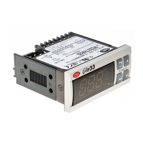
Page 15: User Interface
3. USER INTERFACE The front panel contains the display and the keypad, made up of 4 buttons, that, when pressed alone or combined with other buttons, are used to program the controller. IR33 Universal front panel Fig. 3. a 3.1 Display The display shows temperature in range -50 to +150°C.The temperature is displayed with resolution to the tenths between –19.9 and + 59.9 °C Alternatively, displays the value of one of the analogue or digital inputs... -
Page 16: Keypad
3.2 Keypad Pressing the button alone: • If pressed for more than 5 seconds, accesses the menu for setting the type P parameters (frequent); • Mutes the audible alarm (buzzer) and deactivates the alarm relay; • When editing the parameters, pressed for 5 s, permanently saves the new values of the parameters; •... - Page 17 3.3.3 Setting type P parameters Type P parameters (frequents) are indicated by a code beginning with the letter P, followed by one or two numbers. Press for more than 5 seconds (if an alarm is active, the buzzer is muted), the display shows the code of the fi rst modifi able type P parameter, P1;...
-
Page 18: Example: Setting The Current Date/Time And The On/Off Times
All the modifi cations made to the parameters, temporarily stored in the RAM, can be cancelled, returning to the standard display by not pressing any button for 60 seconds. The values of the clock parameters, however, are saved when entered. If the controller is powered down before pressing , all the modifi cations made to the parameters will be lost... - Page 19 3.4.3 Setting the default parameters To set the parameters to the default values: • Power down the controller; • Press • Power up the controller holding the button, until the message “Std” is shown on the display. This will cancel any changes made and restore the original values set by the manufacturer.
-
Page 20: Using The Remote Control (Accessory)
3.4.10 Displaying the inputs • Press : the current input will be displayed, alternating with the value: b1 : probe 1; b2 : probe 2; di1 : digital input 1; di2 : digital input 2. • Press to select the input to be displayed; •... - Page 21 3.5.2 Activating and deactivating the use of the remote control Button Immediate function Delayed function used to enable the remote control; each instrument displays its own enabling code ends operation using the remote control, cancelling all changes made to the parameters used to display the pressing and holding for 5s...
-
Page 22: Commissioning
4. COMMISSIONING °C 4.1 Confi guration set point The confi guration parameters should be set when commissioning the process value controller, and involve: • serial address for the network connection; • enabling the keypad, buzzer and the remote control (accessory); •... -
Page 23: Functions
5. FUNCTIONS 5.1 Probes (analogue inputs) Par. Description Def Min Max UoM St1 Set point 1 c21 c22 °C/°F The probe parameters are used to : St2 Set point 2 c23 c24 °C/°F • set the type of probe 1=direct •... - Page 24 5.2.2 Reverse (parameter c0=2) 5.2.4 PWM (parameter c0=4) “Reverse” operation is similar to ”direct” operation, however the outputs The control logic in PWM mode uses the dead zone, with the outputs are activated when the value being controlled decreases, starting from activated based on pulse width modulation (PWM).
- Page 25 St1/St2 Set point 1/2 Mod. V Mod. W “Direct” diff erential OUT1 (LOW ALARM) OUT1 OUT2 (HIGH ALARM) “Reverse” diff erential OUT1 Output 1 Probe 1 For models W & Z the activations of the outputs are equally distributed inside the diff erential set (P1/P2). Parameter c29 is not active in mode 6.
-
Page 26: Validity Of Control Parameters (Parameters St1,St2,P1,P2,P3)
• 5.2.9 Direct/reverse with two set points (par. c0=9) Mode 6: does not consider the diff erential P3. The changeover of digital input 1 means the outputs consider set point 2 rather than In this mode, available only on the models with 2 or 4 outputs, half of the set point 1. - Page 27 5.5.1 Dependence (parameters c34,c38,c42,c46) 5.5.3 Activation (parameters c36,c40,c44,c48) This the parameter that determines the specifi c function of each output. The parameter is active only if the output is the control output It links an output to a set point (control output) or a specifi c alarm (alarm (“dependence”=1,2,16,17) or TIMER (“dependence”=15).
- Page 28 output, that is, for ON/OFF operation, the deactivation point of the output 5.5.6 Deactivation restriction (par. d35,d39,d43,d47) or, for PWM operation, the point where the output has the minimum value In normal operating conditions, the deactivation sequence should be as (ON time =0).
-
Page 29: Additional Remarks On Special Operation
The following must also be set: The PWM (or analogue) outputs will follow the operation indicated in • “type of output “ =1, modulating output the fi gure. In practice, in the dead zone the output maintains the level of •... -
Page 30: Outputs And Inputs
Modes 1 & 2 in diff erential operation (c19=1). In diff erential operation, St1 must compare against ‘B1-B2’ instead of B1. Time In special operation (c33=1) the outputs can be set with “dependence”=2: c6 & d1 are not operative for the PWM outputs. diff erential operation is therefore overridden and the outputs are linked to St2/P2 compared against B1. - Page 31 c29=0 Input not active Par. Description Def Min Max UM c12 PWM cycle time 20 0.2 999 s c29=1 Immediate external alarm with automatic reset. The alarm condition relates to the contact being open. When the alarm Validity: c0=4; condition ceases (contact closes), normal control resumes and any alarm In special operation c12 is active in any mode if “type of output”=1 output is deactivated.
-
Page 32: Control
6. CONTROL ON/OFF and PID control 6.3 Auto-Tuning (parameter c64) The controller leaves the factory with default settings of the PID The controller can operate with two types of control: parameters; these allow standard PID control, but are not optimised for the system that IR33 controls. -
Page 33: Operating Cycle
procedure can be repeated to further tune the values. This is useful when Example 1: Heating cycle with infi nite temperature control the loads have changed since the fi rst procedure was performed, or to allow fi ner tuning. The controller in this case can manage the system using the PID parameters, and further Auto-Tuning will have the eff ect of improving control. - Page 34 Example 1: T2< 8°C. To do this, simply connect OUT2 in series with OUT3 and OUT4, A refrigeration unit with 2 compressors must lower the temperature of then make OUT2 active only when B1 (T2) is greater than 8°C. the water by 5°C. Set c33=1: the changes to be made to the special parameters are: OUT2 OUT3...
- Page 35 6.5.3 Compensation in cooling (parameter c19=2) from falling below 10°C, a minimum limit must be set for St1, with c21=10. The graph below shows the trend in St1. Compensation in cooling may either increase or decrease the value of St1, depending on whether c4 is positive or negative. St1_comp St1 only changes if the temperature B2 exceeds St2: c4=-0,5...
- Page 36 6.5.5 Continuous compensation (parameter c19=4) ABILITAZIONE/ ENABLE The compensation of St1 is active for values of B2 other than St2: with C19=5 this value of c19, parameter P2 can be used to defi ne a dead zone around St2 in which compensation is not active, that is, when the value read by B2 is between St2-P2 and St2+P2, compensation is disabled and St1 is not changed: if B2 is greater than (St2+P2), eff ective St1 = St1+ [B2-(St2+P2)]*c4...
-
Page 37: Table Of Parameters
7. TABLE OF PARAMETERS Par. Description Note Def Max UoM Type CAREL SVP ModBus® Icon Set point 1 °C/°F A Set point 2 °C/°F A Operating mode 1=direct 2=reverse 3=dead zone 4=PWM 5=alarm 6=direct/reverse from digital input1 7=direct: set point & diff erential from digital input 1 8=reverse: set point &... - Page 38 Par. Description Note Def Max UoM Typ. CAREL SVP ModBus® Icon High temperature alarm threshold °C/°F if P29=0, P26=0 : threshold disabled if P29=1, P26=200 : threshold disabled Alarm diff erential °C/°F Alarm delay time Type of alarm threshold 0=relative; 1=absolute...
- Page 39 Par. Description Note Def Min Max UoM Typ. CAREL SVP ModBus® Icon Activation of output 4 -100 -100 Diff erential/logic of output 4 -100 Activation restriction for output 4 Deactivation restriction for output 4 Minimum value of modulating output 4(*)
-
Page 40: Variables Only Accessible Via Serial Connection
ModBus® : variable address with ModBus® protocol on 485 serial card. The selection between CAREL and ModBus® protocol is automatic. For both of them the speed is fi xed to 19200 bit/s. All the devices connected to the same network must feature the same serial parameters: - 8 data bit;... -
Page 41: Alarms
8. ALARMS 8.1 Types of alarms There are two types of alarms available: • high temperature (E04) and low temperature (E05); • serious alarms, that is, all the others. The data memory alarms E07/E08 always cause the control to shutdown. “Alarm”... -
Page 42: Table Of Alarms
8.4 Table of alarms Message Cause of the alarm Icon on display Alarm relay Buzzer Reset Code Control action Checks/solutions on display shown in alarm queue ALx_TYPE Probe B1 fault automatic Depends on Check probe connections fl ashing parameter c10 Probe B2 fault automatic If c19=1 &... - Page 43 8.5.3 Status of the control outputs with alarm from Description digital input (parameter c31) Status of the control outputs with probe alarm Parameter c31 determines the action on the control outputs if an alarm 0=All outputs OFF from digital input E03 is active (see c29 and c30). When OFF is selected, 1= All outputs ON the controller shuts down immediately and the timers are ignored.
-
Page 44: Technical Specifications And Product Codes
Note: in the installation, keep the power and load connections separate from the probe, digital inputs, repeater display and supervisor cables. Type of probe Std. CAREL NTC 10kΩ at 25°C, range from –50T90°C measurement error: 1°C in range from –50T50°C 3°C in range from +50T90°C... -
Page 45: Cleaning The Controller
Device designed to be hand-held or integrated in hand-held devices Software class and structure Class A Front panel cleaning Only use neutral detergents and water Carel serial network interface External, available on all models Programming key Available on all models Type of connection Size... -
Page 46: Software Revisions
9.4 Software revisions REVISION Description Functions active starting from software version higher than FUNCTION Parameter Soft start 0 to 10 V outputs c19=5,6 / c66, c67 d36, d40, d44, d48 d37, d41, d45, d49 ir33 universale +030220801 - rel. 1.0 - 16.04.2008... - Page 48 CAREL is a registered trademark of CAREL S.p.A. in Italy and/or other countries. © CAREL S.p.A. 2008 all rights reserved CAREL reserves the right to modify the features of its products without prior notice. www.carel.com...
Need help?
Do you have a question about the ir33 Universale series and is the answer not in the manual?
Questions and answers
currently system is in direct mode and output 1,2 are on display. please assist how to set back to normal display
To change the Carel IR33 system from direct mode to the standard (normal) display, follow these steps:
1. Set parameter c52 appropriately to select the standard display;
or
2. Press the DOWN button to scroll through display options (b1, b2, di1, di2, St1, St2),
3. Press the SET button to confirm the selected display.
This will switch the display from direct mode to the desired standard view.
This answer is automatically generated
currently system is in direct mode. please assist how to set back to normal display
To return the Carel IR33 system to normal display from direct mode (or any parameter setting mode), press no buttons for 10 seconds. The display will start flashing and, after 1 minute, automatically return to the standard display without saving any changes. Alternatively, to save changes and exit, press the button for 5 seconds.
This answer is automatically generated