Advertisement
KNX
825 629 03
Stand: Sep-07
Continuous-action regulator
1. Safety instructions
Electrical equipment must be installed and fitted by qualified
electricians only.
Failure to observe the instructions may cause damage to the device
and result in fire or other hazards.
These operating instructions are part of the product and must be left
with the final customer.
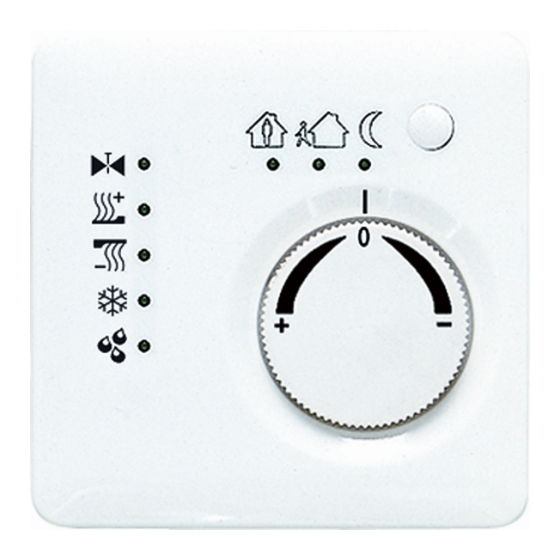
2. Device layout
(Fig. 1)
(1) Presence button
(2) Adjusting wheel
(3) Status LED
3. Function
System information
Stetigregler
Art.-Nr.: ..2178..
Advertisement
Table of Contents

Subscribe to Our Youtube Channel
Related Manuals for Jung 2178 Series


Summary of Contents for Jung 2178 Series
- Page 1 Stetigregler Art.-Nr.: ..2178.. Continuous-action regulator 1. Safety instructions Electrical equipment must be installed and fitted by qualified electricians only. Failure to observe the instructions may cause damage to the device and result in fire or other hazards. These operating instructions are part of the product and must be left with the final customer.
- Page 2 ETS3.0d onwards. The product database, technical descriptions, conversion programs and other utilities are always available in their latest versions in the Internet under www.jung.de. Designated use Single-room temperature regulation in KNX installations. Flush-mounted installation in hollow or in solid walls.
- Page 3 Stetigregler Art.-Nr.: ..2178.. Heating/cooling active indicator Heating mode indicator Cooling mode indicator Controller locked indicator (dew-point mode) The indication of the controller status can last up to 30 s. Setting the mode of operation Control elements for setting the operating mode are installed, e.g. touch sensors, control panels, etc.
- Page 4 Stetigregler Art.-Nr.: ..2178.. be fatal. Before working on the device, disconnect the supply voltage and cover up live parts in the working environment. 4.1. Fitting and electrical connection Fitting and connecting the device The device is composed of a terminal insert with supporting ring and electronic attachment module (Fig.
- Page 5 Stetigregler Art.-Nr.: ..2178.. Install the terminal insert (Fig. 2, 4) in the flush-mounting box. Pay attention to the lettering OBEN / TOP.The bus connection (Fig.3, 10) must be at the bottom. Place the design frame (Fig.2, 5) on the terminal insert (Fig. 2, 4).. Install the electronic attachment module in the correct position on the terminal insert.
- Page 6 We accept the guarantee in accordance with the corresponding legal provisions. Please return the unit postage paid to our central service department giving a brief description of the fault: ALBRECHT JUNG GMBH & CO. KG Service-Center Kupferstr. 17-19 D-44532 Lünen Service-Line: +(49) 23 55 .
Need help?
Do you have a question about the 2178 Series and is the answer not in the manual?
Questions and answers