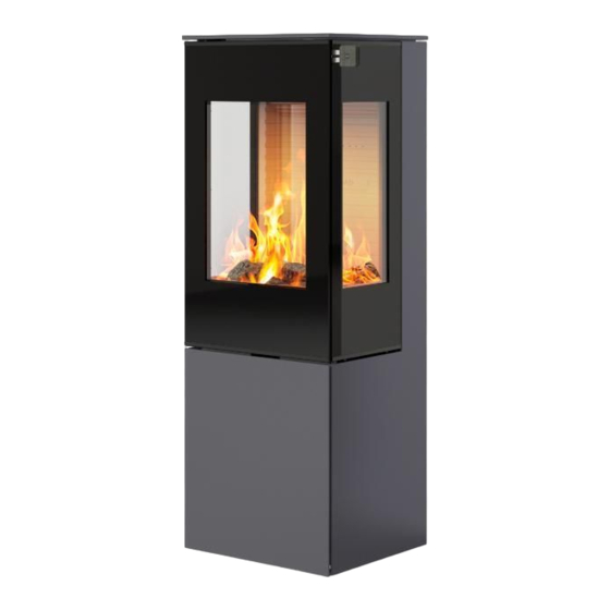
RAIS NEXO 100 GAS Installation Manual
Hide thumbs Also See for NEXO 100 GAS:

Advertisement

Quick Links

GB
CONTENTS
Introduction . . . . . . . . . . . . . . . . . . . . . . . . . . . . . . . . . . . . . . . . . . . . . . . . . . . . . . . . . . . . . . . . . . . . . . 3
Certification . . . . . . . . . . . . . . . . . . . . . . . . . . . . . . . . . . . . . . . . . . . . . . . . . . . . . . . . . . . . . . . . . . . . . . 4
Your new gas fireplace in general . . . . . . . . . . . . . . . . . . . . . . . . . . . . . . . . . . . . . . . . . . . . . . . . . . . . . . 5
Before installation . . . . . . . . . . . . . . . . . . . . . . . . . . . . . . . . . . . . . . . . . . . . . . . . . . . . . . . . . . . . . . 5
Gas connection . . . . . . . . . . . . . . . . . . . . . . . . . . . . . . . . . . . . . . . . . . . . . . . . . . . . . . . . . . . . . . . . 5
Emergency stop of gas supply . . . . . . . . . . . . . . . . . . . . . . . . . . . . . . . . . . . . . . . . . . . . . . . . . . . . . 5
Safety . . . . . . . . . . . . . . . . . . . . . . . . . . . . . . . . . . . . . . . . . . . . . . . . . . . . . . . . . . . . . . . . . . . . . . . 6
Specifications . . . . . . . . . . . . . . . . . . . . . . . . . . . . . . . . . . . . . . . . . . . . . . . . . . . . . . . . . . . . . . . . . . . . . 7
Nexo Gas . . . . . . . . . . . . . . . . . . . . . . . . . . . . . . . . . . . . . . . . . . . . . . . . . . . . . . . . . . . . . . . . . . . . 7
Viva L Gas . . . . . . . . . . . . . . . . . . . . . . . . . . . . . . . . . . . . . . . . . . . . . . . . . . . . . . . . . . . . . . . . . . . . 8
Q-Tee 2 Gas/Q-Tee 2 C Gas . . . . . . . . . . . . . . . . . . . . . . . . . . . . . . . . . . . . . . . . . . . . . . . . . . . . . . . 9
Dimensional drawings . . . . . . . . . . . . . . . . . . . . . . . . . . . . . . . . . . . . . . . . . . . . . . . . . . . . . . . . . . . . . 10
Nexo Gas . . . . . . . . . . . . . . . . . . . . . . . . . . . . . . . . . . . . . . . . . . . . . . . . . . . . . . . . . . . . . . . . . . . 10
Viva L Gas . . . . . . . . . . . . . . . . . . . . . . . . . . . . . . . . . . . . . . . . . . . . . . . . . . . . . . . . . . . . . . . . . . . 13
Q-Tee 2 Gas/Q-Tee 2 C Gas . . . . . . . . . . . . . . . . . . . . . . . . . . . . . . . . . . . . . . . . . . . . . . . . . . . . . . 17
Information plate . . . . . . . . . . . . . . . . . . . . . . . . . . . . . . . . . . . . . . . . . . . . . . . . . . . . . . . . . . . . . . . . . 21
Nexo Gas . . . . . . . . . . . . . . . . . . . . . . . . . . . . . . . . . . . . . . . . . . . . . . . . . . . . . . . . . . . . . . . . . . . 21
Viva L Gas . . . . . . . . . . . . . . . . . . . . . . . . . . . . . . . . . . . . . . . . . . . . . . . . . . . . . . . . . . . . . . . . . . . 22
Q-Tee 2 Gas/Q-Tee 2 C Gas . . . . . . . . . . . . . . . . . . . . . . . . . . . . . . . . . . . . . . . . . . . . . . . . . . . . . . 22
Delivery packaging . . . . . . . . . . . . . . . . . . . . . . . . . . . . . . . . . . . . . . . . . . . . . . . . . . . . . . . . . . . . . . . . 23
Opening of front cover . . . . . . . . . . . . . . . . . . . . . . . . . . . . . . . . . . . . . . . . . . . . . . . . . . . . . . . . . . . . 24
Fitting the burner . . . . . . . . . . . . . . . . . . . . . . . . . . . . . . . . . . . . . . . . . . . . . . . . . . . . . . . . . . . . . . . . . 25
Changing the chimney connection . . . . . . . . . . . . . . . . . . . . . . . . . . . . . . . . . . . . . . . . . . . . . . . . . . . . 27
Flue system . . . . . . . . . . . . . . . . . . . . . . . . . . . . . . . . . . . . . . . . . . . . . . . . . . . . . . . . . . . . . . . . . . . . . 30
Positioning flue terminals . . . . . . . . . . . . . . . . . . . . . . . . . . . . . . . . . . . . . . . . . . . . . . . . . . . . . . . 31
Horizontal wall terminal, type C11 . . . . . . . . . . . . . . . . . . . . . . . . . . . . . . . . . . . . . . . . . . . . . . . . 32
Vertical roof terminal, type C31 . . . . . . . . . . . . . . . . . . . . . . . . . . . . . . . . . . . . . . . . . . . . . . . . . . . 33
Pipework . . . . . . . . . . . . . . . . . . . . . . . . . . . . . . . . . . . . . . . . . . . . . . . . . . . . . . . . . . . . . . . . . . . . 33
Installation distances . . . . . . . . . . . . . . . . . . . . . . . . . . . . . . . . . . . . . . . . . . . . . . . . . . . . . . . . . . . . . . 34
Nexo Gas . . . . . . . . . . . . . . . . . . . . . . . . . . . . . . . . . . . . . . . . . . . . . . . . . . . . . . . . . . . . . . . . . . . 34
Viva L Gas . . . . . . . . . . . . . . . . . . . . . . . . . . . . . . . . . . . . . . . . . . . . . . . . . . . . . . . . . . . . . . . . . . . 39
Q-Tee 2 Gas/Q-Tee 2 C Gas . . . . . . . . . . . . . . . . . . . . . . . . . . . . . . . . . . . . . . . . . . . . . . . . . . . . . . 44
Fitting secondary burners . . . . . . . . . . . . . . . . . . . . . . . . . . . . . . . . . . . . . . . . . . . . . . . . . . . . . . . . . . . 47
Arranging ceramic "logs" and embers layer . . . . . . . . . . . . . . . . . . . . . . . . . . . . . . . . . . . . . . . . . . . . . 48
INSTALLATION MANUAL
GB - 1

Advertisement

Table of Contents
loading
Need help?

Need help?

Do you have a question about the NEXO 100 GAS and is the answer not in the manual?

Questions and answers

Summary of Contents for RAIS NEXO 100 GAS

  • Page 1: Table Of Contents

    INSTALLATION MANUAL CONTENTS Introduction . . . . . . . . . . . . . . . . . . . . . . . . . . . . . . . . . . . . . . . . . . . . . . . . . . . . . . . . . . . . . . . . . . . . . . 3 Certification .
  • Page 2 INSTALLATION MANUAL Remote control and receiver . . . . . . . . . . . . . . . . . . . . . . . . . . . . . . . . . . . . . . . . . . . . . . . . . . . . . . . . . 52 Insertion of batteries in the remote control .
  • Page 3: Introduction

    INTRODUCTION INTRODUCTION Congratulations on the acquisition of your new gas fireplace and on becoming a RAIS or ATTIKA customer! You have chosen a gas fireplace where quality, design and function go hand-in-hand . Follow us on our social media platforms to get the latest tips, know-how and inspiration .
  • Page 4: Certification

    CERTIFICATION Certification This gas fireplace is tested and certified for use in several countries (see the section “information plate”) . The gas fireplace has been tested for use with natural gas, town gas, LPG and biogas . This installation manual covers the following models: Nexo Gas Viva L Gas Q-Tee 2 Gas...
  • Page 5: Your New Gas Fireplace In General

    Your new gas fireplace in general This RAIS/ATTIKA product is a highly efficient convection gas fireplace with a sealed combustion chamber for a balanced flue system . The fireplace has variable heating power and is equipped with a burner which has been developed using the latest burner technology .
  • Page 6: Safety

    SAFETY Safety It is important that the fireplace is correctly installed in consideration of the environment and people’s safety . No unauthorised alterations may be made to the gas fireplace . The fireplace may not be used if the glass is split, cracked or removed . Do not use the fireplace if the glass gasket is broken or worn .
  • Page 7: Specifications

    SPECIFICATIONS - NEXO GAS Specifications Shown below is the technical data for Nexo Gas, Viva L Gas and Q-Tee 2 Gas/Q-Tee 2 C Gas . Nexo Gas Intertek Ref .: NEXO NEXO NEXO NEXO NEXO 102929617LHD-001 100 GAS 120 GAS 140 GAS 160 GAS 185 GAS...
  • Page 8: Viva L Gas

    SPECIFICATIONS - VIVA L GAS Viva L Gas Intertek Ref .: VIVA VIVA VIVA L 140 GAS VIVA L 160 GAS 102929617LHD-001 Nominal output (kW): Natu- 9 .1 9 .1 9 .1 9 .1 ral gas - G20 I2H/I2E Min ./Max . Output (kW): 1 .7–9 .1 1 .7–9 .1 1 .7–9 .1...
  • Page 9: Q-Tee 2 Gas/Q-Tee 2 C Gas

    SPECIFICATIONS Q-TEE 2 GAS/Q-TEE 2 C GAS Q-Tee 2 Gas/Q-Tee 2 C Gas: Intertek Ref .: Q-TEE 2 GAS Q-TEE 2 C GAS 103435815LHD-001 Nominal output (kW): Natu- 9 .1 9 .1 ral gas - G20 I2H/I2E Min ./Max . Output (kW): 1 .7–9 .1 1 .7–9 .1 Natural gas - G20 I2H/I2E...
  • Page 10: Dimensional Drawings

    DIMENSIONAL DRAWINGS - NEXO GAS Dimensional drawings Nexo Gas Nexo 100 Gas A-A ( 0,1 ) 1025 1025 Nexo 120 Gas A-A ( 0,1 ) 1235 1235 1079 1063 10 - GB...
  • Page 11 DIMENSIONAL DRAWINGS - NEXO GAS Nexo 140 Gas 1426 1426 1221 1079 1063 Nexo 160 Gas 1601 1601 1221 1079 1063 GB - 11...
  • Page 12 DIMENSIONAL DRAWINGS - NEXO GAS Nexo 185 Gas 1861 1861 1221 1079 1063 12 - GB...
  • Page 13: Viva L Gas

    DIMENSIONAL DRAWINGS - VIVA L GAS Viva L Gas 295,6 Viva L 100 Gas 3716550 - Viva L Gas 100 GB - 13...
  • Page 14 DIMENSIONAL DRAWINGS - VIVA L GAS Viva L 120 Gas 295,6 1213 1213 1200 1200 1062 3796550 Viva L Gas 120 14 - GB...
  • Page 15 DIMENSIONAL DRAWINGS - VIVA L GAS Viva L 140 Gas GB - 15...
  • Page 16 DIMENSIONAL DRAWINGS - VIVA L GAS Viva L 160 Gas 295,6 1613 1613 1613 1600 1600 1600 1122 1122 3876550 - Viva L Gas 160 16 - GB...
  • Page 17 0.5-3 6-30 30-120 1000-2000 120-400 400-1000 Phone +45 98 47 90 33 - Fax +45 98 47 92 91 Materia E-mail: info@rais.dk - Homepage: www.rais.dk GB - 17 TILLADTE AFVIGELSER FOR VINKELMÅL 0-10 10-50 Drawing name: 50-120 120-400 > 400 KORTESTE SIDE 1°...
  • Page 18 INDUSTRIVEJ 20, 9900 FREDERIKSHAVN, DENM 0.5-3 6-30 30-120 120-400 400-1000 1000-2000 Phone +45 98 47 90 33 - Fax +45 98 47 92 9 E-mail: info@rais.dk - Homepage: www.rais.d TILLADTE AFVIGELSER FOR VINKELMÅL Drawing name: 0-10 10-50 120-400 50-120 > 400 KORTESTE SIDE 1°...
  • Page 19: Q-Tee 2 Gas/Q-Tee 2 C Gas

    DIMENSIONAL DRAWINGS - Q- TEE 2 C GAS Q-Tee 2 C Gas Q-Tee 2 C Gas Q-Tee 2 C Gas with low base D M Y Corrections: Change order GB - 19 Drawing change: Improve...
  • Page 20 INDUSTRIVEJ 20, 9900 FREDERIKSHAVN 0.5-3 6-30 30-120 120-400 400-1000 1000-2000 Phone +45 98 47 90 33 - Fax +45 98 E-mail: info@rais.dk - Homepage: ww TILLADTE AFVIGELSER FOR VINKELMÅL Q-Tee II C Gl Drawing name: 0-10 10-50 120-400 50-120 > 400 KORTESTE SIDE 1°...
  • Page 21: Information Plate

    RAIS A/S, Industrivej 20, 9900 Frederikshavn, Danmark NEXO 100 Gas / NEXO 100 G Gas / NEXO 100 Classic Gas / NEXO 100 G Classic Gas NEXO 120 Gas / NEXO 120 G Gas / NEXO 120 Classic Gas / NEXO 120 G Classic Gas ...
  • Page 22: Viva L Gas

    AT, CH, CZ, DE, FR, SK 50 mbar SVGW Nr. 18-035-3 Hergestellt für /Produced for: ATTIKA FEUER AG, Brunnmatt 16, CH-6330 Cham / RAIS A/S, Industrivej 20, DK-9900 Frederikshavn Information plate: Q-Tee 2 Gas/Q-Tee 2 C Gas: Nr. 18-035-3 2575-21...
  • Page 23: Delivery Packaging

    DELIVERY PACKAGING Delivery packaging The fireplace is supplied secured to a transport pallet using four transport safety fittings – one in each corner (A) . The safety fittings are secured using three screws and these must be removed . The safety fittings can then be removed (B) .
  • Page 24: Opening Of Front Cover

    OPENING OF FRONT COVER Opening of front cover The fireplace is supplied with the front cover fitted . The front cover must be opened in order to fit the fireplace burner . To open the front cover use the accompanying fork spanner* to turn the three hooks in the top and bottom of the front cover .
  • Page 25: Fitting The Burner

    FITTING THE BURNER Fitting the burner On delivery, the gas fireplace burner is supplied separated from the base plate . Follow these steps to fit the gas burner . Remove the four front-fitted screws on the bottom of the fireplace . Fit the burner in the combustion chamber using the four screws .
  • Page 26 FITTING THE BURNER Position the reflective insulation panel above the burner . Position the bottom grate above the burner and reflective insulation panel . 26 - GB...
  • Page 27: Changing The Chimney Connection

    CHANGING CHIMNEY CONNECTION Changing chimney connection The fireplace is supplied ready for connection to the top outlet but can be changed to use the bottom outlet by following this procedure: Tap out the cover behind the gas fireplace using a hammer .
  • Page 28 CHANGING CHIMNEY CONNECTION Loosen the three screws on the inner flange in the combustion chamber . Remove it . Remove the small side plates by removing the lock in the top of the plates . To do this, push the lock up . Next, remove the side pieces . The rear plate can now be removed and the inner cover plate can be detached .
  • Page 29 CHANGING CHIMNEY CONNECTION Now fit the inner cover plate to the underside of the top plate, as shown . Fit the spigots where the cover plates were and replace the rear plate . GB - 29...
  • Page 30: Flue System

    This fireplace may be installed with either a roof terminal (C31) or a wall terminal (C11) . The fireplace may only be installed using a balanced flue (also known as concentric flue system) in the way stated by RAIS/ ATTIKA .
  • Page 31: Positioning Flue Terminals

    POSITIONING FLUE TERMINALS Positioning flue terminals The table below shows how different flue terminals can be positioned in the house . Dimension Terminal position Distance Directly below an opening, an opening window or ventilation See national regulatory requirements . duct . Directly above an opening, an opening window or ventilation See national regulatory requirements .
  • Page 32: Horizontal Wall Terminal, Type C11

    HORIZONTAL WALL TERMINAL, TYPE C11 Horizontal wall terminal, type C11 Dimensions of flue pipe: The fireplace is supplied with an outlet spigot, dimension Ø100/Ø150 mm . This flue dimension can be used for the entire flue . Alternatively, a Ø130/Ø200 adapter can be fitted, so that this flue dimension can be used for the rest of the flue .
  • Page 33: Vertical Roof Terminal, Type C31

    VERTICAL ROOF TERMINAL, TYPE C31 Vertical roof terminal, type C31 Dimensions of flue pipe: The fireplace is supplied with an outlet spigot Ø100/Ø150 mm or Ø130/Ø200 mm, depending on the mod- el . This flue dimension can be used for the entire flue . Alternatively, a Ø130/Ø200 adapter can be fitted, so that this flue dimension can be used for the rest of the flue .
  • Page 34: Installation Distances

    Project manager: Approved: D M Y INDUSTRIVEJ 20, 9900 FREDERIKSHAVN, DENMARK Corrections: Phone +45 98 47 90 33 - Fax +45 98 47 92 91 E-mail: info@rais.dk - Homepage: www.rais.dk Nexo Gas - Retvinklet opstilling Drawing name: Project: Established: Format: Revision: Drawing no.:...
  • Page 35 Project manager: Approved: D M Y INDUSTRIVEJ 20, 9900 FREDERIKSHAVN, DENMARK Corrections: Phone +45 98 47 90 33 - Fax +45 98 47 92 91 E-mail: info@rais.dk - Homepage: www.rais.dk Nexo G Gas - Retvinklet opstilling Drawing name: Project: Established: Format: Revision: Drawing no.:...
  • Page 36 Project manager: Approved: D M Y INDUSTRIVEJ 20, 9900 FREDERIKSHAVN, DENMARK Corrections: Phone +45 98 47 90 33 - Fax +45 98 47 92 91 E-mail: info@rais.dk - Homepage: www.rais.dk Nexo Gas 45° opstilling Drawing name: Project: Established: Format: Revision: Drawing no.:...
  • Page 37 Project manager: Approved: D M Y INDUSTRIVEJ 20, 9900 FREDERIKSHAVN, DENMARK Corrections: Phone +45 98 47 90 33 - Fax +45 98 47 92 91 E-mail: info@rais.dk - Homepage: www.rais.dk Nexo G Gas 45° opstilling Drawing name: Project: Established: Format: Revision: Drawing no.:...
  • Page 38 Corner installation 45° D M Y INDUSTRIVEJ 20, 9900 FREDERIKSHAVN, DENMARK Corrections: Phone +45 98 47 90 33 - Fax +45 98 47 92 91 E-mail: info@rais.dk - Homepage: www.rais.dk NEXO GAS ikke brændbar væg Drawing name: Project: Established: Format: Revision: Drawing no.:...
  • Page 39: Viva L Gas

    INSTALLATION DISTANCES - VIVA L GAS Viva L Gas - at flammable wall We recommend a minimum distance of 75 mm to non-flammable material in consideration of servicing and installation work . Normal installation - right-angle Minimum distance to flammable material Without side glass Non-insulated flue Minimum distance to furniture...
  • Page 40 INSTALLATION DISTANCES - VIVA L GAS Normal installation - right-angle Minimum distance to flammable material With side glass Non-insulated flue Minimum distance to furniture 700 mm 3716502 Viva L Gas Med sideglas 90° opstilling Rear (wall) 50 mm From side to wall 300 mm 40 - GB...
  • Page 41 INSTALLATION DISTANCES - VIVA L GAS Corner installation 45° Minimum distance to flammable material Without side glass Non-insulated flue Minimum distance to furniture 700 mm Rear (wall) 50 mm 3716503 Viva L Gas uden sideglas 45° opstilling GB - 41...
  • Page 42 INSTALLATION DISTANCES - VIVA L GAS Corner installation 45° Minimum distance to flammable material With side glass Non-insulated flue Minimum distance to furniture 700 mm Rear (wall) 150 mm 3716504 Viva L Gas med sideglas 45° opstilling 42 - GB...
  • Page 43 INSTALLATION DISTANCES - VIVA L GAS Viva L Gas - at non-flammable wall If the wall is non-flammable (brick, concrete, etc .), we recommend a minimum distance of 75 mm to non-flammable material in consideration of servicing and installation work . However, at the rear outlet there must be sufficient space for a measuring spigot for combustion checks .
  • Page 44: Q-Tee 2 Gas/Q-Tee 2 C Gas

    INSTALLATION DISTANCES - Q-TEE 2 GAS/Q-TEE 2 C GAS Q-Tee 2 Gas/Q-Tee 2 C Gas - at flammable wall We recommend a minimum distance of 75 mm to non-flammable material in consideration of servicing and installation work . Normal installation - right-angle Minimum distance to flammable material 12-6542 Without side glass...
  • Page 45 INSTALLATION DISTANCES - Q-TEE 2 GAS/Q-TEE 2 C GAS Corner installation 45° Minimum distance to flammable material Non-insulated flue Minimum distance to furniture 700 mm Rear (wall) 50 mm Q-Tee 2 Gas Q-Tee 2 C Gas GB - 45...
  • Page 46 INSTALLATION DISTANCES - Q-TEE 2 GAS/Q-TEE 2 C GAS Q-Tee 2 Gas/Q-Tee 2 C Gas - at non-flammable wall If the wall is non-flammable (brick, concrete, etc .), we recommend a minimum distance of 75 mm to non-flammable material in consideration of servicing and installation work . However, at the rear outlet there must be sufficient space for a measuring spigot for combustion checks .
  • Page 47: Fitting Secondary Burners

    FITTING SECONDARY BURNERS Fitting secondary burners The burners must be set down over the pipe that sticks through the perforated plate . NB: There is a left burner and a right burner . This means that it is important that the burners are positioned as shown, i .e .
  • Page 48: Arranging Ceramic "Logs" And Embers Layer

    CERAMIC “LOGS” AND THE EMBERS LAYER Arranging ceramic “logs” and embers layer It is very important that you follow this when positioning ceramic “logs” and the embers layer in the fireplace . Failure to carry this out correctly will result in a flame profile that is less than optimal . When arranging ceramic “logs”...
  • Page 49 ARRANGING CERAMIC “LOGS” AND THE EMBERS LAYER Arranging ceramic “logs” and the embers layer Below you can see the different ceramic “logs” that are used specifically with your fireplace . Identify the different logs and then follow the guide’s instructions in how to position them correctly . It is very important that you follow the instructions for positioning the ceramic “logs”...
  • Page 50 ARRANGING CERAMIC “LOGS” AND THE EMBERS LAYER Procedure: 2 . Position log no . 1 as shown in the image . 1 . Start by securing two burners in the fireplace’s base plate (see the section Fitting secondary burners for the detailed procedure) . 3 .
  • Page 51 ARRANGING CERAMIC “LOGS” AND THE EMBERS LAYER 7 . Position log no . 6 as shown in the image . 8 . Position log A on the left burner . 10 . Spread the embers layer over the base plate . 9 .
  • Page 52: Remote Control And Receiver

    REMOTE CONTROL AND RECEIVER Remote control and receiver The following electronic parts accompany this gas fireplace: Receiver Remote control Remote control In this section you can learn how to set up the remote control for the gas fireplace . See the separate user manual for how to use the remote control .
  • Page 53: Connection Of Myfire Wi-Fi-Box

    CONNECTION OF MYFIRE WI-FI-BOX Connection of MyFire wi-fi-box If you wish to use more than the accompanying remote control, the gas fireplace can also be remotely controlled using an app on a smartphone or tablet . To do this you must connect a MyFire wi-fi-box . MyFire wi-fi-box (accessory) To connect the MyFire wi-fi-box with the receiver, which is positioned behind the inspection hatch, you...
  • Page 54: Configuration Of Myfire App

    CONFIGURATION OF THE MYFIRE APP Configuration of the MyFire app Read this section to learn how to configure the MyFire app on your smart phone or tablet . When you configure the MyFire app, you must use your SSID key and code for the wireless network (wi-fi) .
  • Page 55 CONFIGURATION OF THE MYFIRE APP To connect the MyFire-wi-fi-box to the wi-fi router (home network) you must ensure that: • The home network is accessible . • The name and code for the network is correct . • The wi-fi-router SSID key is not hidden . •...
  • Page 56: Starting The Gas Fireplace

    STARTING THE GAS FIREPLACE Starting the gas fireplace Learn how to start up the gas fireplace after installation in this section . Pressure test The fireplace is pre-set to provide the correct amount of heat (kW), which is described under the specifi- cations .
  • Page 57: Functional Test When Lighting The Fire For The First Time

    STARTING THE GAS FIREPLACE Functional test when lighting the fire for the first time Read this section to learn how to check the function of the start-up of your gas fireplace . 1 . Light the fireplace . 2 . The pilot flame ignites . 3 .
  • Page 58: Lighting For First Time

    STARTING THE GAS FIREPLACE Lighting for first time See the separate user manual for how to use the remote control . Before lighting the fire for the first time, ensure that all of the packaging, labels etc . are removed from the fireplace and the glass is cleaned .
  • Page 59: Service And Maintenance

    Switch off the fireplace and shut off the gas supply . Make sure the fireplace is completely cold before you begin . RAIS/ATTIKA cannot be held liable for injuries that result from touching a hot fireplace . Service procedure proposal: 1 .
  • Page 60: Cleaning

    If the glass has a layer of soot, clean the glass using a special glass cleaner which can be purchased from your RAIS/ RAIS dealer . However, be aware that non-reflecting glass must never be cleaned using special glass cleaner – only use water . Only clean the glass when the fireplace is cold .
  • Page 61: Warranty

    . • RAIS/ATTIKA is not liable for faults or defects caused by the installation of the gas fireplace . The authorised installation technician is responsible for approving the position of the fireplace, choice of materials and installation of the flue pipe .
  • Page 62: Accessories

    ACCESSORIES Accessories Nexo Gas: 10-0000-060980 - Top plate for rear outlet, stainless steel 10-0000-061080 - Top plate for top outlet, stainless steel 10-0000-061170 - Top plate for rear outlet, soapstone 10-0000-061270 - Top plate for top outlet, soapstone 2796521 - 6 kg thermal storage stone, set of 4 Viva L Gas: 2710611SV - Stainless steel classic top plate for rear outlet 2710612SV - Stainless steel classic top plate for top outlet...
  • Page 63: Spare Parts List

    SPARE PARTS LIST - NEXO GAS Spare parts list If spare parts other than those recommended by RAIS/ATTIKA are used, the warranty is rendered void . All replaceable parts can be purchased as spare parts from your RAIS/ATTIKA dealer .
  • Page 64 SPARE PARTS LIST - NEXO GAS Nexo 100 G Gas - 120 G Gas - 140 G Gas - 160 G Gas - 185 G Gas Pos . Item no . Description 10-0000-100490 Glass front cover 10-0000-1005XX Classic glass front cover 10-0000-0601XX Top plate for rear outlet 10-0000-0602XX...
  • Page 65: Viva L Gas

    SPARE PARTS LIST - VIVA L GAS Viva L 100 Gas – Viva L 120 Gas – Viva L 140 Gas – Viva L 160 Gas Pos . Item no . Description 37120XX Glass front cover 37121XX Classic glass front cover 2710601XX Top plate for rear outlet 2710602XX...
  • Page 66 SPARE PARTS LIST - VIVA L GAS Viva L 100 G Gas – Viva L 120 G Gas – Viva L 140 G Gas – Viva L 160 G Gas Pos . Item no . Description 37120XX Glass front cover 37121XX Classic glass front cover 2710601XX...
  • Page 67: Q-Tee 2 Gas/Q-Tee 2 C Gas

    8380529XX High legs 12-0000-5502 Gasket set for glass front cover 12-0000-5501 Gasket set for classic front cover INDUSTRIVEJ 20, 9900 FRE Phone +45 98 47 90 33 E-mail: info@rais.dk - H Q-Tee Drawing name: Project: Esta 05-0 GB - 67...
  • Page 68 12-0000-5504 Gasket set for glass front cover 12-0000-5503 Gasket set for classic front cover INDUSTRIVEJ 20, 9900 FREDERIKSH Phone +45 98 47 90 33 - Fax +45 E-mail: info@rais.dk - Homepage: Q-Tee II C Drawing name: Project: Established: 05-03-2018 68 - GB...
  • Page 69: Gas Unit

    SPARE PARTS LIST - GAS UNIT Gas unit If spare parts other than those recommended by RAIS/ATTIKA are used, the warranty is rendered void . All replaceable parts can be purchased as spare parts from your RAIS/ATTIKA dealer . Pos .
  • Page 70: Technical Information

    TECHNICAL INFORMATION Technical information Country specific gas types and pressure Country Natural gas AT-Austria I2H, G20 at 20 mbar I3P(50), G31 at 50 mbar, I3B/P(50), G30/G31 at 50 mbar BE-Belgium I2E+, G20/G25 at 20/25 mbar I3+, G31/G31 at 28/37 mbar, I3P(37), G31 at 37 mbar, I3B/P(30), G30/G31 at 30 mbar BG-Bulgaria I2H, G20 at 20 mbar...
  • Page 71 TECHNICAL INFORMATION Country Natural gas LT-Lithuania I2H, G20 at 20 mbar I3+, G31/G31 at 28/37 mbar, I3P(37), G31 at 37 mbar, I3B/P(30), G30/G31 at 30 mbar LU-Luxembourg I2E, G20 at 20 mbar LV -Latvia I2H, G20 at 20 mbar MT-Malta I3B/P(30), G30/G31 at 30 mbar NL-The Netherlands I2L, G25 at 25 mbar...
  • Page 72: Technical Data

    TECHNICAL DATA Technical data Product identification number 0359CS1717 Gas type G20/G25 G25/G25 .3 G20/G25 (Natural gas - LNG) I2H, I2E I2E+ I2L / I2EK I2ELL I2 (43 .46 -45 .3 MJ/ m3 (0°C)) Supply Pressure mbar 20/25 Nominal Heat Input 9 .1 9 .1 / 8 .4 8 .5...
  • Page 73 TECHNICAL DATA Gas type G30/G31 G30/G31 (Liquid petroleum gas - LPG) I3B/P(30) I3P(50) I3P(37) I3P(30) Supply Pressure mbar 30 / 37 Nominal Heat Input Gross (Hs) Nominal Heat Input 7 .4 7 .4 7 .4 7 .4 7 .4 Net (Hi) Consumption m³/hr 0 .225...
  • Page 74: Examples Of Flue System Solutions

    EXAMPLES OF FLUE SOLUTIONS Examples of flue solutions Vertical roof terminal Distance “V” 500 mm – 12 m (min–max) 1,2,3,6 74 - GB...
  • Page 75 EXAMPLES OF FLUE SOLUTIONS Vertical roof terminal - existing chimney 17 (3-3) (PT 3 of 3) (Flexible smoke duct routing Ø100 AISA-316Ti) 17 (2-3) (PT 2 of 3) 17 (1-3) (PT 1 of 3) 1,2,3,6 GB - 75...
  • Page 76 EXAMPLES OF FLUE SOLUTIONS Vertical pitched roof terminal 18,19 1,2,3,6 11,12,13 1,2,3,6 Distance “H” = 0–3 m (min–max) Distance “V1” 500 mm – 10 m (min–max) Distance “V2” 500 mm – 10 m (min–max) Distance “V3” 500 mm – 10 m (min–max) Distance “V”...
  • Page 77 EXAMPLES OF FLUE SOLUTIONS Vertical roof terminal with bend 18,19 1,2,3,6 1,2,3,6 1,2,3,6 Distance “H” = 0–3 m (min–max) Distance “V1” 500 mm – 10 m (min–max) Distance “V2” 500 mm – 10 m (min–max) Distance “V” (= V1+V2) = 1–12 m (min–max) Distance “V”...
  • Page 78 EXAMPLES OF FLUE SOLUTIONS Existing chimney (renovation drawing) 17 (3-3) (PT 3 of 3) (Flexible smoke duct routing Ø100 AISA-316Ti) 17 (2-3) (PT 2 of 3) 17 (1-3) (PT 1 of 3) 1,2,3,6 Distance “V” 1–12 m (min–max) *Existing chimney/smoke duct must be inspected by a qualified technician . 78 - GB...
  • Page 79 EXAMPLES OF FLUE SOLUTIONS Vertical roof terminal/existing chimney with bend (renovation drawing) 17 (3-3) (PT 3 of 3) (Flexible smoke duct routing Ø100 AISA-316Ti) 17 (2-3) (PT 2 of 3) 17 (1-3) (PT 1 of 3) 1,2,3,6 Distance “H” = 0–3 m (min–max) Distance “V1”...
  • Page 80 EXAMPLES OF FLUE SOLUTIONS Vertical roof terminal with rear outlet See the section “Positioning of flue terminals” for more information . 80 - GB...
  • Page 81 EXAMPLES OF FLUE SOLUTIONS Horizontal wall terminals See the section “Positioning of flue terminals” for more information . GB - 81...
  • Page 82 EXAMPLES OF FLUE SOLUTIONS Horizontal wall terminals See the section “Positioning of flue terminals” for more information . Top outlet Rear outlet Snorkel terminal Snorkel ter- minal 82 - GB...
  • Page 83: Flue Parts

    FLUE PARTS US 100 100 (Ø100) US 100 130 (Ø130) Flue parts Length 1000 mm US 25 100 (Ø100) US 25 130 (Ø130) Length 250 mm US 50 100 (Ø100) US 50 130 (Ø130) Length 500 mm USKB 100 (Ø100) USKB 130 (Ø130) Hose clip USAB 100 (Ø100)
  • Page 84 FLUE PARTS USDV2 100 (Ø100) Vertical terminal USPP 100 (Ø100) (+ USKB) USPP 130 (Ø130) Adjustable length USDHCE 100 Horizontal terminal (Eccentric outlet) USMB 100 (Ø100) USMB 130 (Ø130) Adjustable wall clip USEB 100 (Ø100) USEB 130 (Ø130) Assembly clip 84 - GB...
  • Page 85 FLUE PARTS USB 90 100 (Ø100) USSR 100 (Ø100) USB 90 130 (Ø130) USSR 130 (Ø130) 90° bend Flashing USDPAL 100 (Ø100) USDPAL 130 (Ø130) Aluminium USB 45 100 (Ø100) USB 45 130 (Ø130) 45° bend USDP 100 (Ø100) USDP 130 (Ø130) USB 15 100 (Ø100) Flat roof flashing USB 15 130 (Ø130)
  • Page 86 FLUE PARTS USDH 100 (Ø100) USMPG 100 (Ø100) USDH 130 (Ø130) USMPG 130 (Ø130) Inclined flashing Wall cover 5–30° USLS 100 (Ø100) USLS 130 (Ø130) Inclined flashing 20–45° USA Ø 100 130 USA D 99 Adaptor USCP 100 (Ø100) USCP 130 (Ø130) Adjustable flashing (Supplied as pair) 86 - GB...
  • Page 87: Performance Declaration

    DECLARATION OF PERFORMANCE GB - 87...
  • Page 88: Viva L Gas

    DECLARATION OF PERFORMANCE 88 - GB...
  • Page 89: Q-Tee 2 Gas/Q-Tee 2 C Gas

    DECLARATION OF PERFORMANCE GB - 89...
  • Page 90: Declaration Of Conformity

    DECLARATION OF CONFORMITY 90 - GB...
  • Page 91: Viva L Gas

    DECLARATION OF CONFORMITY GB - 91...
  • Page 92: Q-Tee 2 Gas/Q-Tee 2 C Gas

    DECLARATION OF CONFORMITY 92 - GB...
  • Page 93: Troubleshooting

    TROUBLESHOOTING TROUBLESHOOTING See the troubleshooting section in the separate user guide . GB - 93...
  • Page 94 94 - GB...

Table of Contents