
Subscribe to Our Youtube Channel
Related Manuals for RAIS 600-1


Summary of Contents for RAIS 600-1
- Page 1 R-600 INSTALLATIONSVEJLEDNING INSTALLATIONSANLEITUNG INSTALLATION GUIDE NOTICE D’INSTALLATION INSTALLASJONSVEILEDNING INSTALLATIONSANVISNING ASENNUSOHJEET INSTALLATIEHANDLEIDING...
-
Page 2: Table Of Contents
INSTALLATION MANUAL CONTENTS Installation manual In general Chimney Technical data Specifications Dimensional sketches Information plate Installation Delivery packaging Choice of material for installation Installation dimensions 600-1 Installation distance 600-1 Installation dimensions 600-2 Installation distance 600-2 Installation dimensions 600-3 Installation distance 600-3 Heat distributor External air connection Fitting the floor plate Lubricating hinges Combustion chamber lining Cleaning the flue Performance declaration Test certificate We are not responsible for typographical errors. -
Page 3: Installation Manual
INSTALLATION MANUAL INSTALLATION MANUAL CHIMNEY Congratulations on the acquisition of your new RAIS or The chimney must be high enough to ensure that the chimney ATTIKA product! This installation manual will ensure that your draught conditions are correct, i.e. –14 to –18 pascal. If fireplace insert is installed correctly and that it will provide you the recommended chimney draught cannot be achieved, with comfort and pleasure for many years to come. problems from smoke escaping from the door may arise when lighting the fire. We recommend that the chimney is adapted to suit the flue outlet spigot. The flue outlet spigot is 150 mm IN GENERAL in diameter. -
Page 4: Technical Data
TECHNICAL DATA SPECIFICATIONS Danish Technological Institute ref.: 300-ELAB-2431-EN RAIS 600-1 RAIS 600-2 RAIS 600-3 Nominal output (kW) Min./max. output (kW) 4 - 8 * 4 - 8 * 4 - 8 * Heating area (m Fireplace insert width/depth/height (mm) 720 X 402 X 610 699 X 402 X 610 678 X 402 X 610 Combustion chamber W x D x H (mm) 544 X 255 X165 ** 544 X 255 X165 ** 544 X 255 X165 ** Min. uptake (pascal) Weight (kg) min., dependent on model Efficiency (%) CO emission attributed to 13% O (%) 0.0915 (1144 mg/Nm³) 0.0915 (1144 mg/Nm³) 0.0915 (1144 mg/Nm³) NOx emission attributed to 13% O (mg/Nm³) OGC emission attributed to 13% O (mg/Nm³) Particle emission in accordance with 2.11 2.11 2.11 NS3058/3059 (g/kg) -
Page 5: Dimensional Sketches
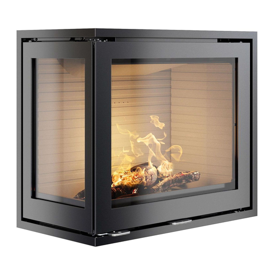
DIMENSIONAL SKETCHES 600-1 11-0000-6550 R600 Front model, Glass * AirSystem ** Interior dimensions All dimensions are in mm. 4 - EN... - Page 6 DIMENSIONAL SKETCHES 600-2 (right) 264,5 404,5 699 ** 11-0000-6552 R600 Right model, Glass * AirSystem ** Interior dimensions All dimensions are in mm. EN - 5...
- Page 7 DIMENSIONAL SKETCHES 600-2 (left) 264,5 404,5 699 ** 11-0000-6554 R600 Left model, Classic * AirSystem ** Interior dimensions All dimensions are in mm. 6 - EN...
- Page 8 DIMENSIONAL SKETCHES 600-3 264,5 404,5 678 ** 11-0000-6556 R600 3G model, Glass * AirSystem ** Interior dimensions All dimensions are in mm. EN - 7...
-
Page 9: Information Plate
F: Veuillez lire et observer les instructions du mode d'emploi. Foyer à durèe de combustion limitèe, homologué pour cheminée à connexions multiples. Utiliser seulement les combustibles recommandés. Hergestellt für /Produced for: ATTIKA FEUER AG, Brunnmatt 16, CH-6330 Cham / RAIS A/S, Industrivej 20, DK-9900 Frederikshavn 30-08-2 8 - EN... - Page 10 Rais 600 Classic Right model, Rais 600 Classic Left model, Rais 600 Classic 3 Side model Rais 600 Right model CA, Rais 600 Left model CA, Rais 600 3 Side model CA Rais 600 Classic Right model CA, Rais 600 Classic Left model CA, Rais 600 Classic 3 Side model CA AFSTAND TIL BRÆNDBART, BAGVÆG...
-
Page 11: Installation
INSTALLATION INSTALLATION The following section explains how to install the fireplace insert and includes information about the packaging, installation distances, etc. DELIVERY PACKAGING The fireplace insert is supplied secured to a transport pallet using four transport safety fittings. The safety fittings are secured with screws and these must be removed. The safety fitting can then be removed. A ( 0,5 ) A ( 0,5 ) There is a polystyrene block in the top of the fireplace insert which secures the baffle during transport. The polystyrene block must be removed before starting a fire in the stove. -
Page 12: Choice Of Material For Installation
The material can be panels/brick with an insulation value greater than 0.03 m² x K/W. The insulation is defined as wall thickness (in metres) divided by the wall’s Lambda value. Contact your installation technician/chimney inspector. During testing, the fireplace insert is installed in a cabinet made from non-flammable 50 mm calcium silicate panels (Skamotec 225). The fireplace insert must be installed in heat-resistant material. See the following pages for the installation dimensions and the installation distances for 600-1, 600-2 and 600-3. EN - 11... -
Page 13: Installation Dimensions 600-1
The minimum area for convection air above and below the Ceiling fireplace insert can be distributed for several cavities. 500 cm² 500 cm² 250 cm² 250 cm² 500 cm² 250 cm² RAIS 600 Indbygningsmål 1G Skamotec RAIS 600 Indbygningsmål 1G Skamotec RAIS 600 Indby 12 - EN... -
Page 14: Installation Distance 600-1
INSTALLATION DISTANCE INSTALLATION DISTANCE: 600-1 A non-flammable panel must be fitted directly above the convection opening so that “standing” hot air does not develop above the convection opening. This is done to protect the ceiling and to transport the heat out of the fireplace insert. The insulated part of the chimney must extend all the way down to the flue spigot. DISTANCE FROM DISTANCE IN MM... -
Page 15: Installation Dimensions 600-2
The minimum area for convection air above and below the fireplace insert can be distributed for several cavities. 500 cm² 500 cm² 250 cm² 500 cm² Ceiling 250 cm² 250 cm² 500 cm² 250 cm² RAIS 600 Indbygningsmål 2G skamotec RAIS 600 Indbygningsmål 2G skamotec RAIS 600 In 14 - EN... -
Page 16: Installation Distance 600-2
INSTALLATION DISTANCE INSTALLATION DISTANCE: 600-2 A non-flammable panel must be fitted directly above the convection opening so that “standing” hot air does not develop above the convection opening. This is done to protect the ceiling and to transport the heat out of the fireplace insert. The insulated part of the chimney must extend all the way down to the flue spigot. DISTANCE FROM DISTANCE IN MM Furniture to door Furniture to side glass Panels to fireplace insert... -
Page 17: Installation Dimensions 600-3
The minimum area for convection air above and below the 500 cm² fireplace insert can be distributed for several cavities. 500 cm² 250 cm² 250 cm² 500 cm² 250 cm² 500 cm² 250 cm² RAIS 600 Indbygningsmål 3G Skamote RAIS 600 Indbygningsmål 3G Skam 16 - EN RAIS 600 I... -
Page 18: Installation Distance 600-3
INSTALLATION DISTANCE INSTALLATION DISTANCE: 600-3 A non-flammable panel must be fitted directly above the convection opening so that “standing” hot air does not develop above the convection opening. This is done to protect the ceiling and to transport the heat out of the fireplace insert. The insulated part of the chimney must extend all the way down to the flue spigot. DISTANCE FROM DISTANCE IN MM Furniture to door Furniture to side glass Panels to fireplace insert... -
Page 19: Heat Distributor
HEAT DISTRIBUTOR HEAT DISTRIBUTOR By installing a heat distributor unit above the fireplace insert, heat can be ‘transported’ to other rooms. 18 - EN... -
Page 20: External Air Connection
EXTERNAL AIR CONNECTION - AIRSYSTEM EXTERNAL AIR CONNECTION - AIRSYSTEM All RAIS/ATTIKA fireplace inserts can have an external air connection for combustion. We call this external air supply AirSystem. The system can be connected to the underside or the rear of the fireplace insert. INSTALLING AN AIR KIT ON THE UNDERSIDE ITEM PART NUMBER... - Page 21 EXTERNAL AIR CONNECTION - AIRSYSTEM INSTALLING AN AIR KIT ON THE REAR SIDE Remove the cover on the rear side of the fireplace insert and ITEM PART NUMBER TITLE detach the cover plate (6) using a 3 mm Allen key (5). 1710912sv Air connexion Slangebånd ABA Ø87/112 0710-SLANGEBÅND Re-fit the cover plate to the underside of the fireplace insert 0710-FLEKSSLANGE using the four M5 screws (4) ensuring that the air box is sealed. 0110-M5x6 CYL RÅ LH 0110-M5x6 CYL RÅ...
-
Page 22: Fitting The Floor Plate
FITTING THE FLOOR PLATE FITTING THE FLOOR PLATE RAIS/ATTIKA supply elegant floor plates made from hardened glass that are designed for the shape of the fireplace insert. Floor plates can be purchased separately. The floor plate is simply pushed in against the fireplace insert, which allows for occasional cleaning under the plate. EN - 21... -
Page 23: Lubricating Hinges
LUBRICATING HINGES LUBRICATING HINGES The fireplace must be lubricated regularly using the four moving parts on the lock and hinges (see image). Use heat- resistant oil. 22 - EN... -
Page 24: Combustion Chamber Lining
REMOVING THE COMBUSTION CHAMBER LINING REMOVING THE COMBUSTION CHAMBER LINING The combustion chamber lining protects the body of the fireplace insert from the heat from the fire. The large differences in temperature can lead to cracks in the combustion chamber lining. This will not affect the functionality of the fireplace insert. The lining will only need be replaced after several years of use when it begins to disintegrate. The liner panels are simply placed in position by hand and can easily be replaced by you or your dealer. Procedure to remove the combustion chamber lining: Remove the flue panel (1) by pushing the front up and pulling forward, so that the rear end becomes free of the vertical panels. The flue panel can now be carefully removed. -
Page 25: Cleaning The Flue
CLEANING THE FLUE CLEANING THE FLUE Remove the flue panel by pushing the front up and pulling forward, so that the rear end becomes free of the vertical panels. The flue panel can now be carefully removed. Remove the steel baffle by pushing the rear end up, freeing it from the bracket. 24 - EN... - Page 26 CLEANING THE FLUE Push the baffle back sufficiently to free it from the bearing surfaces in the front of the fireplace insert. Fit the parts in reverse order. EN - 25...
-
Page 27: Performance Declaration
DECLARATION OF PERFORMANCE DECLARATION OF PERFORMANCE 26 - EN... - Page 28 EN - 27...
- Page 29 RAIS A/S ATTIKA FEUER AG Industrivej 20 Brunnmatt 16 DK-9900 Frederikshavn CH-6330 Cham Denmark Switzerland www.rais.dk www.attika.ch...
Need help?
Do you have a question about the 600-1 and is the answer not in the manual?
Questions and answers