Table of Contents
Advertisement
Quick Links
Advertisement
Table of Contents

Related Manuals for RAIS attika NEXO 100 Gas


Summary of Contents for RAIS attika NEXO 100 Gas
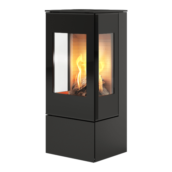
- Page 1 All manuals and user guides at all-guides.com N E X O G A S POSITIV...
- Page 2 GR, HR, HU, IT, LT, MT, NL, NO, 30 mbar RO, SE, SI, SK, TR I3B/P(50) G30↔G31 @ AT, CH, CZ, DE, FR, SK 50 mbar Hergestellt für /Produced for: ATTIKA FEUER AG, Brunnmatt 16, CH-6330 Cham / RAIS A/S, Industrivej 20, DK-9900 Frederikshavn...
- Page 3 All manuals and user guides at all-guides.com This stove had been tested and certificated for several countries (see the rating plate). It may be necessary to adjust the stove for safe and correct use in your coun- try/area. This stove has been tested and certificated for use with natural gas, LPG and bio- propane.
-
Page 4: Table Of Contents
All manuals and user guides at all-guides.com Revision : Date 01-04-2019 INTRODUCTION .........................5 GUARANTEE ...........................6 SPECIFICATIONS ........................7 DISTANCE/TEMPLATE ......................7 GENERAL GENERAL REMARKS .......................8 EMERGENCY INTERRUPTION OF GAS SUPPLY .................9 INSTALLATION OF STOVE INSTALLATION ........................10 GAS CONNECTION .......................10 VENTILATION ........................10 GAS INSTALLATION .......................10 CHANGING THE CHIMNEY CONNECTION................11 CONVERSION TO BOTTLED GAS (LPG) ..................14 NORMAL INSTALLATION - RECTANGULAR WITHOUT SIDE GLASS .........21... -
Page 5: Introduction
All manuals and user guides at all-guides.com Introduction Congratulation on your new RAIS / attika Product. attika A RAIS/ stove is more than just a source of heat, it also express- es how you put the emphasis on good design and high quality in your home. -
Page 6: Guarantee
All manuals and user guides at all-guides.com Guarantee attika RAIS/ stoves are checked several times with regard to safety, as well as the quality of materials and manufacturing. We offer a 2 year guarantee on all models and the guarantee commences on the date of installation. -
Page 7: Specifications
All manuals and user guides at all-guides.com Specifications Intertek Ref.: NEXO 100 NEXO 120 NEXO 140 NEXO 160 NEXO 185 102929617LHD-001 Nominal heat input (kW): Natural Gas - G20 I2H/I2E Min/Max input (kW): 1.7 - 9.1 1.7 - 1.9 1.7 - 1.9 1.7 - 1.9 1.7 - 1.9 Natural Gas - G20 I2H/I2E... -
Page 8: General
General General Comments attika This RAIS/ product is an extremely effective convection gas stove with a sealed combustion chamber for chimneys with a balanced draught. It is fitted with a burner with the latest burner technology. It has a var-... - Page 9 All manuals and user guides at all-guides.com This stove is designed for use in many different installation situations, which can be seen in this manual. Only chimneys approved by RAIS/ tika may be used with this product. (see chimney section)
-
Page 10: Emergency Interruption Of Gas Supply
All manuals and user guides at all-guides.com Emergency interruption of gas supply Where a smell of gas is detected, the gas supply must be interrupted immediately. Turn off the stove at the isolation tap and the gas meter Ventilate the room by opening windows and doors, do not use electrical appliances in the vicinity of the stove. -
Page 11: Installation Of Stove Installation
All manuals and user guides at all-guides.com installation of stove Installation It is important that the stove is correctly installed from both an environ- mental and safety point of view. The stove must only be installed by a Gas Safe Registered engineer. When installing the stove, all local rules and regulations, including those referring to national and European standards must be complied with. -
Page 12: Gas Installation
All manuals and user guides at all-guides.com Gas installation Once it has been decided where the stove will be positioned, a gas in- stallation should be established in the vicinity of the stove so that the gas supply and stove can be connected. As this stove has a sealed combustion chamber and a built-in plinth, there is no need for a floor slab. - Page 13 All manuals and user guides at all-guides.com PLEASE NOTE! The floor construction must be able to bear the weight of the stove and chimney, if applicable. If the existing design does not satisfy this prereq- uisite, suitable measures must be taken (e.g., a load distribution slab). Consult a construction expert.
- Page 14 All manuals and user guides at all-guides.com 2. Loosen the three screws on the outer flange on the top surface of the stove. And remove it. 3. To open the door, a 14mm open-ended span- ner is required to turn the two catches at the top and bottom of the door.
- Page 15 All manuals and user guides at all-guides.com 7. If the ceramic logs are fitted, remove these. 8. The thin side pieces of the back plate are removed by removing the locking brackets at the top. This is done by pushing the brack- et upwards.
-
Page 16: Conversion To Bottled Gas (Lpg)
All manuals and user guides at all-guides.com Conversion to bottled gas (LPG) The stove is supplied configured for natural gas but can be converted to bottled gas (LPG). The conversion must only be carried out by a Gas Safe Registered engineer. Conversion kit. - Page 17 All manuals and user guides at all-guides.com The injector for the main burner for LPG is marked "80" The injector for the main burner for nat- ural gas is marked "120" The injector for the pilot light for LPG is marked "27" The injector for the pilot light for natural gas is marked "32"...
- Page 18 All manuals and user guides at all-guides.com The gas unit needs to be dismantled to gain access to the injectors. Do this in the following manner: Lift the perforated plate up and out of the stove. Remove the reflector plate Loosen the four screws holding the gas unit in place.
- Page 19 All manuals and user guides at all-guides.com Now the gas unit can be lifted out carefully by tilting and rotating the unit a little. Once the gas unit has been dismounted, replace the four injectors and adjust the three air intakes. Replace the two injectors for the second- ary burners by loosening the coupling and carefully pulling the pipe out.
- Page 20 All manuals and user guides at all-guides.com Remove the injector for the main burner by loosening the coupling and carefully pulling the pipe out and then unscrewing the injec- tor. Fit the LPG injector and tighten the lock nut. Finally, re-tighten the coupling. Replace the injector for the pilot light by loosening the coupling and carefully pull- ing the pipe out.
- Page 21 All manuals and user guides at all-guides.com The air intake to the main burner is adjust- ed for LPG configuration by loosening the two nuts and pushing the plate all the way towards the burner. (The hole fully open) The two air intakes for the secondary burn- er are adjusted for LPG configuration by loosening the two screws and rotating the air intake by 90°.
- Page 22 All manuals and user guides at all-guides.com The air intakes need to be reversed therefore when the stove is config- ured for LPG. Burner pressure is adjusted according to the gas type on the rating plate and checked in the PROPANE field.
- Page 23 All manuals and user guides at all-guides.com Installation distance from flammable wall In order to clarify whether the wall your stove will stand alongside is flammable, you can contact your building architect or the local building authorities. It must be ensured that flammable objects (e.g., furniture) are not positioned closer than the distances stated in the following tables (risk of fire).
- Page 24 All manuals and user guides at all-guides.com Normal installation - at right angle With side glass A. Furniture distance (min.) 700 mm Distance to flammable material (min.) D. rear (wall) 50 mm E. to side to wall 300 mm INDUSTR Phon E-ma Drawing n...
- Page 25 All manuals and user guides at all-guides.com Corner installation 45° Without side glass A. Furniture distance (min.) 700 mm Distance to flammable material (min.) D. rear (wall) 50 mm INDUSTRIV Phone E-mail Drawing nam Project:...
- Page 26 All manuals and user guides at all-guides.com Corner installation 45° With side glass A. Furniture distance (min.) 700 mm Distance to flammable material (min.) D. rear (wall) 150 mm INDU Drawin Projec...
- Page 27 Project manager: Approved: D M Y INDUSTRIVEJ 20, 9900 FREDERIKSHAVN, DENMARK Corrections: Phone +45 98 47 90 33 - Fax +45 98 47 92 91 E-mail: info@rais.dk - Homepage: www.rais.dk NEXO GAS ikke brændbar væg Drawing name: Project: Established: Format: Revision: Drawing no.:...
- Page 28 (C11) Must only be installed with a flue with a balanced draught (also known as a concentric draft) as stated by RAIS/attika. The flues approved by RAIS/attika are approved for use with the stove. If the stove is installed with flues other than those approved. RAIS/attika cannot guarantee or accept responsibility for the correct and safe func- tioning of the stove.
-
Page 29: Location Of Chimney Terminals
All manuals and user guides at all-guides.com Location of chimney terminals Distance (mm) Dimension Terminal Position Directly under an opening, an open window or ventilation duct Above an opening, an open window or ventilation duct Alongside an opening, opening window etc. Under gutter, earth pipes or drainpipes Under eaves Under balconies or carport roof... -
Page 30: Horizontal Wall Terminal Type C11
All manuals and user guides at all-guides.com Horizontal Wall Terminal type C11 Dimension of outflow pipe: Ø100 / Ø150 Outlet connection piece on the stove Ø100 / Ø150 Can be used for the entire chimney, or, Ø130 / Ø200 Adapter can be used so that you can use Ø130 / Ø200 after the adapter. - Page 31 All manuals and user guides at all-guides.com Vertical roof terminal type C31 Dimension of outflow pipe: Ø100 / Ø150 Outlet connection piece on the stove Ø100 / Ø150 Can be used for the entire chimney, or, Ø130 / Ø200 Adapter can be used so that you can use Ø130 / Ø200 after the adapter.
- Page 32 All manuals and user guides at all-guides.com Fitting of Secondary burners The burners are inserted above the pipes sticking through the perforated plate. Note that there is a right burner and a left one so it is important that they are posi- tioned as shown, i.e., that the side with the extra holes faces the front.
-
Page 33: Arrangement Of "Embers" And "Logs
All manuals and user guides at all-guides.com Arrangement of "Embers" and ”Logs" When layers of embers and the ceramic logs are arranged in the com- bustion chamber, it is important that the pilot flame and its thermosen- sor are not covered over. And that no glowing material finds its way down under the pilot plate guard. - Page 34 All manuals and user guides at all-guides.com ceramic "Logs Log A Log 1 Log B Log 2 Log 3 Log 4 Log 5 Log 6...
- Page 35 All manuals and user guides at all-guides.com Positioning of Logs and Embers Spread the content of the bag of "Embers" as shown in the illustration. Note: The pilot area must be kept clear of "Embers". Be sure not to block the holes of the center burner. Position the 8 logs as shown. Note, the two special logs marked A and B have a groove moulded on their undersides that fits on top of the two secondary burners.
- Page 36 All manuals and user guides at all-guides.com Log 3 Log 4 Log 5...
- Page 37 All manuals and user guides at all-guides.com Log 6 Log A Log B...
-
Page 38: Start-Up
All manuals and user guides at all-guides.com Start-up Insertion of Batteries. The receiver on the stove and the remote con- trol use batteries. A set of batteries to be inserted prior to start- up is included. To access the battery box on the receiver, open the cover by pulling it to- wards you and lifting it off. - Page 39 All manuals and user guides at all-guides.com The batteries in the receiver must face the directions shown in the illustration. The remote control uses 2 x AA 1.5 V batteries.
-
Page 40: Setting Up The Electronic Code
All manuals and user guides at all-guides.com SETTING UP OF THE ELECTRONIC CODE In order for the remote control to work, it must be synchronised with the stove's receiver. A code is selected automatically and at random from 65,000 possible codes. The stove and remote control are synchronised in the following manner. -
Page 41: Commissioning
All manuals and user guides at all-guides.com Commissioning Check functioning of pilot light. See User Instructions for use of remote control. 1. Start the pilot light. 2. Check that the pilot light remains ignited. 3. Turn off the pilot light. Check the functioning of the main burner. - Page 42 All manuals and user guides at all-guides.com Pressure Test The stove is preset to provide the correct amount of heat (kW) as de- scribed under specifications. There is usually no need for further adjust- ment. "Inlet pressure" and ”Burner pressure” must ALWAYS be meas- ured.
-
Page 43: Initial Ignition
All manuals and user guides at all-guides.com Initial ignition Before the initial ignition, ensure that all packaging, labels etc. have been removed from the stove and that the door glass has been cleaned. Begin at low output, then the stove can be slowly turned up to a great- er output. -
Page 44: User Instructions
All manuals and user guides at all-guides.com User instructions USER INSTRUCTIONS NOTE: When you press on a deactivated button, GENERAL NOTES nothing happens and two horizontal lines are dis- played. The wiring for valves and receiver must be closed off before NOTE: Deactivation remains in effect after replace- the ignition is put on. - Page 45 All manuals and user guides at all-guides.com Signal control Child proofing Time Thermostatic mode Battery status Countdown timer Fahrenheit or Celsius Program mode Eco mode Temperature Help function SETTING OF FAHRENHEIT or CELSIUS CHILD PROOFING Change between °C and °F by pressing and holding the Activation takes place by pressing the...
- Page 46 All manuals and user guides at all-guides.com HOW TO IGNITE IN STANDBY MODE (PILOT LIGHT) HANDSET •Press and hold down the button to set the appli- When pilot ignition is confirmed, the motor auto- ance to pilot light. matically goes to maximum flame height. One-button operation of handset HOW TO EXTINGUISH THE FIRE (Default setting)
- Page 47 All manuals and user guides at all-guides.com •High flame is activated Program mode by double-clicking on the button HI is displayed. PROGRAMS 1 and 2 can both be programmed to start or stop at specific times at a set temperature. Eco mode If the appliance does not work, follow the guidance The flame height fluctuates...
- Page 48 All manuals and user guides at all-guides.com PROGRAM MODE SETTING THE DAY: 1 or 2, 5. ALL flashes. Press the Press the button ON or OFF is displayed. button to select from ALL, SA:SU, 1, 2, 3, 4, 5, 6, 7. 6.
- Page 49 All manuals and user guides at all-guides.com SA:SU or Daily Timer ( 1 , 2, 3, 4, 5, 6, 7) is select- • Set operating time and time for shut down by using the same approach as during "ALL selected" (above). •...
- Page 50 All manuals and user guides at all-guides.com...
- Page 51 All manuals and user guides at all-guides.com...
-
Page 52: Service
Service. Turn off the stove and shut off the gas supply. Ensure the stove is com- pletely cold before starting. Rais/attika cannot be held responsible for injuries arising from touching a hot stove. Proposed service procedure. -
Page 53: Cleaning
Remove the ceramic logs as described in points 1 - 4 under Service. Clean the ceramic parts carefully with a soft brush and a vacuum cleaner. Only replace damaged parts with original Rais specified parts. Pack scrap ceramics in plastic bags and deliver to the correct waste loca- tions. - Page 54 This is done by removing the 4 bolts holding the burner in place. Now the burner can be lifted out of the combustion chamber. Now there is free access to the nozzles. When parts are replaced, only replace these with original Rais/attika specified parts.
-
Page 55: Accessories
All manuals and user guides at all-guides.com Accessories 2796521 - 6KG heat accumulation stone for 4 in a set. 10-0000-060980 - Topplate B/O Stainless - Back Outlet 10-0000-061080 - Topplate T/O Stainless - Top Outlet 10-0000-061170 - Top plate NEXO Soapstone B/O - Back Outlet 10-0000-061270 - Top plate NEXO Soapstone T/O - Top Outlet 3713595 - Propane Gas LP Conversion kit 3713506 - Mains Adapter... - Page 56 All manuals and user guides at all-guides.com...
-
Page 57: Myfire Wi-Fi Box
All manuals and user guides at all-guides.com Installation of MyFire Wi-Fi Box The stove can be controlled remotely via an APP for your smart phone or tablet. The MyFire Wi-Fi Box is connected to the Receiver, which is placed un- der the combustion chamber by opening the stove door and inserting the narrow plug on the Wi-Fi lead into the opening marked ”SI”. - Page 58 All manuals and user guides at all-guides.com CONFIGURATION OF THE MYFIRE APP CONFIRM THE SETTINGS FOR THE FIREPLACE When configuring the MyFire app you will need the After confirming the settings for fireplace, touch the SSID key and access code for the wireless network "Finish"...
- Page 59 Spare parts list: NEXO 100 gas - 120 gas - 140 Gas - 160 gas - 185 Gas If spare parts other than those recommended by RAIS/attika are used, the guarantee will be invalidated. All replaceable parts can be purchased as spare parts from your RAIS/atti- ka dealer.
- Page 60 Spare parts list: NEXO 100 G Gas - 120 G Gas - 140 G Gas - 160 L G Gas - 185 G Gas If spare parts other than those recommended by RAIS are used, the guar- antee will be invalidated.
-
Page 61: Spare Part List Gas Unit
All manuals and user guides at all-guides.com Spare parts list: Gas unit If spare parts other than those recommended by RAIS/attika are used, the guarantee will be invalidated. All replaceable parts can be purchased as spare parts from your RAIS/ attika dealer. Pos. Number Article no. -
Page 62: Technical Information
All manuals and user guides at all-guides.com Technical Information Country Natural AT -Austria I2H, G20 at 20 mbar I3P(50),G31 at 50 mbar; I3B/ P(50),G30/G31 at 50 mbar BE -Belgium I2E+, G20/G25 at 20/25 I3+,G31/G31 at 28/37 mbar; I3P- mbar (37),G31 at 37 mbar;... - Page 63 All manuals and user guides at all-guides.com Country Natural GR -Greece I2H, G20 at 20 mbar I3+,G31/G31 at 28/37 mbar; I3P(37),G31 at 37 mbar; I3B/ P(30),G30/G31 at 30 mbar HU-Hungary I3B/P(30),G30/G31 at 30 mbar HR -Croa- I2H, G20 at 20 mbar I3P(37),G31 at 37 mbar;...
-
Page 64: Technical Data
All manuals and user guides at all-guides.com Technical Data Product Identification Number: 0359CS1717 Gas type G20/G25 G25/G25.3 G20/G25 I2H,I2E I2E+ I2L/ I2EK I2ELL (Natural Gas - LNG) Supply Pressure mbar 20/25 Nominal Heat Input 9.1 / 8.4 Gross (Hs) Nominal Heat Input 8.2 / 7.6 Nett (Hi) Consumption... - Page 65 All manuals and user guides at all-guides.com Gas type G30/G31 G30/G31 I3B/P(30) I3P(50) I3P(37) I3P(30) (liquid petroleum gas - LPG) Supply Pressure mbar 30 / 37 Nominal Heat Input Gross (Hs) Nominal Heat Input Nett (Hi) Consumption m³/hr 0.225 0.225 / 0.29 0.29 0.253...
-
Page 66: Examples Of Chimney Solutions
All manuals and user guides at all-guides.com EXAMPLES OF CHIMNEY SOLUTIONS Vertical Roof Terminal Distance ”V” 500mm - 12m (min. - Max) 1,2,3,6... - Page 67 All manuals and user guides at all-guides.com Vertical Roof Terminal (Renovation kit) 17 (3-3) (PT 3 of 3) (Flexible flue insert Ø100 AISI-316Ti) 17 (2-3) (PT 2 of 3) 17 (1-3) (PT 1 of 3) 1,2,3,6 If the existing chimney is not completely sound the air inlet must also be lined (recommended)
- Page 68 All manuals and user guides at all-guides.com Vertical Pitched Roof Terminal 18,19 1,2,3,6 11,12,13 1,2,3,6 Distance ”H” = 0-3m (Min - Max) Distance ”V1” = 500mm - 10m (Min - Max) Distance ”V2” = 200mm - 10m (Min - Max) Distance ”V3”...
- Page 69 All manuals and user guides at all-guides.com Vertical Roof Terminal with Bend 18,19 1,2,3,6 1,2,3,6 1,2,3,6 Distance ”H” = 0-3m (Min - Max) Distance ”V1” = 500mm - 10m (Min - Max) Distance ”V2” = 500mm - 10m (Min - Max) Distance ”V”...
- Page 70 All manuals and user guides at all-guides.com Existing chimney (Renovations kit) 17 (3-3) (PT 3 of 3) (Flexible flue insert) Ø100 AISI-316Ti) 17 (2-3) (PT 2 of 3) 17 (1-3) (PT 1 of 3) 1,2,3,6 Distance ”V” = 1m - 12m (Min - Max) *Existing chimney/Flue must be inspected by a qualified technician.
- Page 71 All manuals and user guides at all-guides.com Existing chimney with Bend (Renovations kit) 17 (3-3) (PT 3 of 3) (Flexible flue insert Ø100 AISA-316Ti) 17 (2-3) (PT 2 of 3) 17 (1-3) (PT 1 of 3) 1,2,3,6 If the existing chim- ney is not completely sound the air inlet Distance ”H”...
- Page 72 All manuals and user guides at all-guides.com Vertical Roof Terminal with Back outlet for more information see paragraph Location of chimney terminals...
- Page 73 All manuals and user guides at all-guides.com Horizontal wall Terminal for more information see paragraph Location of chimney terminals...
- Page 74 All manuals and user guides at all-guides.com Horizontal wall Terminal for more information see paragraph Location of chimney terminals Top outlet Back outlet Snorkel Snorkel...
-
Page 75: Chimney Components
All manuals and user guides at all-guides.com Chimney components. US 100 100 (Ø100) US 100 130 (Ø130) Length 1000mm US 25 100 (Ø100) US 25 130 (Ø130) US 50 100 (Ø100) Length 250mm US 50 130 (Ø130) Length 500mm USAB 100 (Ø100) USAB 130 (Ø130) Protective band USKB 100 (Ø100) - Page 76 All manuals and user guides at all-guides.com USPP 100 (Ø100) USPP 130 (Ø130) Adjustable length USDV2 100 (Ø100) Vertical Terminal (+ USKB) USDHCE 10 Horizontal Terminal (Eccentric outlet) USMB 100 (Ø100) USMB 130 (Ø130) Adjustable Wall Strap USEB 100 (Ø100) USEB 130 (Ø130) Fitting strap...
- Page 77 All manuals and user guides at all-guides.com USB 90 100 (Ø100) USSR 100 (Ø100) USB 90 130 (Ø130) USSR 130 (Ø130) 90° elbow bend Cover USDPAL 100 (Ø100) USDPAL 130 (Ø130) Flat roof Cover USB 45 100 (Ø100) Aluminium USB 45 130 (Ø130) 45°...
- Page 78 All manuals and user guides at all-guides.com USDH 100 (Ø100) USDH 130 (Ø130) Angular Cover 5° - 30° USMPG 100 (Ø100) USMPG 130 (Ø130) Wall Cover USLS 100 (Ø100) USLS 130 (Ø130) Angular Cover 20° - 45° ADAPTOR (UNIVERSAL SYSTEM ADAPTOR) USA Ø...
-
Page 79: Declaration Of Performance
NEXO 185 Gas, NEXO 185 G Gas, NEXO 185 Classic Gas, NEXO 185 G Classic Gas, 2. Type Balanced Flue Gas Stoves 3. Intended use Domestic room heater NPD Manufacturer Telephone +45 98 47 90 33 RAIS A/S Telefax +45 98 47 92 91 Industrivej 20, Vangen DK-9900 Frederikshavn, Webmail kundeservice@rais.dk Denmark Homepage www.rais.com... - Page 80 All manuals and user guides at all-guides.com NEXO 100 Gas dimensional drawing. 1025 1025 1025 1025 1025 1025...
- Page 81 All manuals and user guides at all-guides.com NEXO 120 Gas dimensional drawing. 1235 1235 1235 1235 1235 1235 1079 1063 1079 1063 1079 1063...
- Page 82 All manuals and user guides at all-guides.com NEXO 140 Gas dimensional drawing. 1426 1426 1426 1426 1079 1221 1079 1063 1079...
- Page 83 All manuals and user guides at all-guides.com NEXO 160 Gas Måltegning. 1601 1601 1601 1601 1601 1601 1221 1221 1079 1063 1079 1063 1221 1079 1063...
- Page 84 All manuals and user guides at all-guides.com NEXO 185 Gas Måltegning. 1861 1861 1861 1861 1861 1861 1221 1079 1221 1063 1079 1063 1221 1079 1063...
- Page 85 All manuals and user guides at all-guides.com NEXO Gas 100, 120, 140, 160, 185...
- Page 86 All manuals and user guides at all-guides.com NEXO G Gas 100, 120, 140, 160, 185...
- Page 87 All manuals and user guides at all-guides.com...
- Page 88 All manuals and user guides at all-guides.com ATTIKA FEUER AG Brunnmatt 16 CH-6330 Cham Switzerland www.attika.ch RAIS A/S Industrivej 20 DK-9900 Frederikshavn Denmark www.rais.dk...
Need help?
Do you have a question about the attika NEXO 100 Gas and is the answer not in the manual?
Questions and answers