Table of Contents
Advertisement
Quick Links
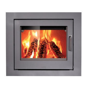
RAIS INSERT 60
FIREPLACE INSERT ENCLOSURE
INSTALLATION INSTRUCTIONS
RAIS A/S
Industrivej 20
9900 Frederikshavn
Denmark
TEL: +45 98 47 90 33
RAIS, Inc.
1011 Highway 52 West
Portland, TN 37148 USA
TEL: 615-325-1700
MODEL NO: 4034801100
Report #138-S-15-2
INSTALLER: Leave this manual with the appliance.
CONSUMER: Retain this manual for future reference.
Advertisement
Table of Contents

Subscribe to Our Youtube Channel
Related Manuals for RAIS INSERT 60


Summary of Contents for RAIS INSERT 60
-
Page 1: Installation Instructions
RAIS INSERT 60 FIREPLACE INSERT ENCLOSURE INSTALLATION INSTRUCTIONS RAIS A/S Industrivej 20 9900 Frederikshavn Denmark TEL: +45 98 47 90 33 RAIS, Inc. 1011 Highway 52 West Portland, TN 37148 USA TEL: 615-325-1700 MODEL NO: 4034801100 Report #138-S-15-2 INSTALLER: Leave this manual with the appliance. -
Page 2: Product Safety
IN PROPERTY DAMAGE, BODILY INJURY OR EVEN DEATH. The Insert 60 Fireplace Insert Enclosure may be ele- vated off the floor to allow the Insert 60 to be placed FOR FUTHER INFORMATION, REFER TO THE NA- higher up on the wall. This will require construction of TIONAL FIRE PROTECTION ASSOCIATION ANSI/NFPA a base structure to support the enclosure and insert. -
Page 3: Chimney Requirements
Next slide the stainless steel 45° slip connector elbow all CHIMNEY REQUIREMENTS the way onto the stainless flex connector in preparation for installing the Insert 60. Note: Do not use the black 45° elbow that is shipped with the Insert 60. For proper draft and best performance, the chimney should extend at least 15’... -
Page 4: Chimney Installation
CHIMNEY INSTALLATION With the Insert 60 Fireplace Insert Enclosure secured to the framing, the chimney system may now be installed. Follow the chimney manufacturer’s instructions exactly... -
Page 5: Framing Dimensions
MINIMUM CLEARANCES TO ADJACENT RECOMMENDED ROUGH COMBUSTIBLE MATERIALS FRAMING DIMENSIONS Ceiling D = 60 1/2” (1537mm) Minimum Top of enclosure support structure when enclosure is elevated off floor FIG. 2 Framing Front View FIG. 5 Combustible / Non-Combustible Material Limits E = 39 3/8”... -
Page 6: Hearth Requirements
24 1/4” (616mm) above the For tile, veneer brick or stone, the finish material may top flange on the Insert 60. See Fig. 9. The mantel may be applied over non-combustible tile backer board. - Page 7 Prepare the Insert 60 sert enclosure, it should be lined with non- 1. After removing the Insert 60 from the shipping enclo- combustible materials. If the wood storage compart- sure, remove the front door by lifting it off the hinges.
Need help?
Do you have a question about the INSERT 60 and is the answer not in the manual?
Questions and answers