Table of Contents
Advertisement
Quick Links
Advertisement
Table of Contents

Related Manuals for RAIS NEXO USA


Summary of Contents for RAIS NEXO USA
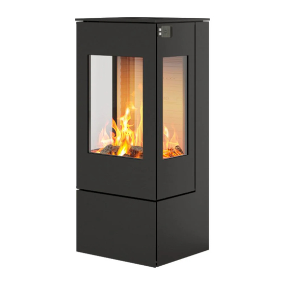
- Page 1 NEXO USA USER MANUAL (US)
-
Page 2: Table Of Contents
LIST OF CONTENT INTRODUCTION Fire environmentally friendly ........Recycling . - Page 3 LIST OF CONTENT FIREWOOD Drying and storage ..........USING THE STOVE Adjusting the combustion air .
-
Page 4: Introduction
INTRODUCTION FIRE ENVIRONMENTALLY FRIENDLY! 5 Eco-friendly advices for sensible heating - common sense both environmentally and economically. Effective lighting. Use small pieces of wood (fir tree) and a suitable fire lighter, for example paraffined wood wool/sawdust. Open the air damper, so plenty of air is fed to the stove and the gases from the heated wood can burn rapidly. -
Page 5: Introduction To User Manual
Congratulations on the purchase of your new RAIS woodburning stove. A RAIS woodburning stove is more than just a source of heat, it is a symbol of the em- phasis you put on decorating your home with superiorly designed high-quality prod- ucts. -
Page 6: Safety And Environmental Testing
Date: WARRANTY We offer a five-year warranty on your RAIS stove. The warranty covers any defects in materials or workmanship. However, it does not cover damage from misuse or neglect, and the glass, gaskets and firebricks are not covered either. Warranties are void if the unit is used to burn any materials other than wood or not operated in accordance with this owner’s manual... -
Page 7: Convection
GLASS AND REPLACEMENT OF GLASS All RAIS stoves supplied with Robax® glass in the door. Robax® glass is a ceramic glass type suitable for stoves. The glass is installed from RAIS as an integral part of the door and stove. -
Page 8: Production Number & Name Tag
INTRODUCTION PRODUCTION NUMBER The production number can be found on the back of the stove. NAME TAG The name tag can be found on the back of the stove. -
Page 9: Specifications
SPECIFICATIONS... -
Page 10: Drawings
DRAWINGS NEXO 100 USA Dimensional sketch 220 [8.7 in] 220 [8.7 in] 220 [8.7 in] 390 [15.4 in] 440 [17.3 in] 390 [15.4 in] 390 [15.4 in] 440 [17.3 in] 440 [17.3 in] 446 [17.6 in] 220 [8.7 in] 446 [17.6 in] 446 [17.6 in] 220 [8.7 in] 220 [8.7 in]... - Page 11 DRAWINGS NEXO 100 USA - with side window Dimensional sketch 220 [8.7 in] 220 [8.7 in] 220 [8.7 in] 390 [15.4 in] 440 [17.3 in] 390 [15.4 in] 390 [15.4 in] 390 [15.4 in] 440 [17.3 in] 440 [17.3 in] 446 [17.6 in] 220 [8.7 in] 446 [17.6 in]...
- Page 12 DRAWINGS NEXO 120 USA Dimensional sketch 220 [8.7 in] 390 [15.4 in] 390 [15.4 in] 440 [17.3 in] 440 [17.3 in] 390 [15.4 in] 440 [17.3 in] 220 [8.7 in] 390 [15.4 in] 440 [17.3 in] 446 [17.6 in] 220 [8.7 in] 223 [8.8 in] 446 [17.6 in] 220 [8.7 in]...
- Page 13 DRAWINGS NEXO 120 USA - with side window Dimensional sketch 440 [17.3 in] 440 [17.3 in] 220 [8.7 in] 390 [15.4 in] 390 [15.4 in] 390 [15.4 in] 440 [17.3 in] 220 [8.7 in] 390 [15.4 in] 440 [17.3 in] 446 [17.6 in] 220 [8.7 in] 223 [8.8 in]...
- Page 14 DRAWINGS NEXO 140 USA Dimensional sketch 220 [8.7 in] 390 [15.4 in] 440 [17.3 in] 220 [8.7 in] 390 [15.4 in] 440 [17.3 in] 446 [17.6 in] 220 [8.7 in] 223 [8.8 in] 446 [17.6 in] 220 [8.7 in] 223 [8.8 in] TILLADTE AFVIGELSER FOR LINIEÆRE MÅ...
- Page 15 DRAWINGS NEXO 140 USA - with side window Dimensional sketch 220 [8.7 in] 390 [15.4 in] 440 [17.3 in] 220 [8.7 in] 390 [15.4 in] 440 [17.3 in] 446 [17.6 in] 220 [8.7 in] 223 [8.8 in] 446 [17.6 in] 220 [8.7 in] 223 [8.8 in] TILLADTE AFVIGELSER FOR LINIEÆRE MÅ...
- Page 16 DRAWINGS NEXO 160 USA Dimensional sketch 220 [8.7 in] 390 [15.4 in] 440 [17.3 in] 220 [8.7 in] 390 [15.4 in] 440 [17.3 in] 446 [17.6 in] 220 [8.7 in] 223 [8.8 in] 446 [17.6 in] 220 [8.7 in] 223 [8.8 in] TILLADTE AFVIGELSER FOR LINIEÆRE MÅ...
- Page 17 DRAWINGS NEXO 160 USA - with side window Dimensional sketch 220 [8.7 in] 390 [15.4 in] 440 [17.3 in] 220 [8.7 in] 390 [15.4 in] 440 [17.3 in] 446 [17.6 in] 220 [8.7 in] 223 [8.8 in] 446 [17.6 in] 220 [8.7 in] 223 [8.8 in] TILLADTE AFVIGELSER FOR LINIEÆRE MÅ...
- Page 18 DRAWINGS NEXO 185 USA Dimensional sketch 220 [8.7 in] 390 [15.4 in] 440 [17.3 in] 220 [8.7 in] 390 [15.4 in] 440 [17.3 in] 446 [17.6 in] 220 [8.7 in] 223 [8.8 in] TILLADTE AFVIGELSER FOR LINIEÆRE MÅ 0.5-3 6-30 30-120 120-400 446 [17.6 in]...
- Page 19 DRAWINGS NEXO 185 USA - with side window Dimensional sketch 220 [8.7 in] 390 [15.4 in] 440 [17.3 in] 220 [8.7 in] 390 [15.4 in] 440 [17.3 in] 446 [17.6 in] 220 [8.7 in] 223 [8.8 in] TILLADTE AFVIGELSER FOR LINIEÆRE MÅ 0.5-3 6-30 30-120...
-
Page 20: Technical Information
TECHNICAL INFORMATION... - Page 21 TECHNICAL INFORMATION TO PREVENT HOUSE FIRES Contact local Building or Fire offi cials about restrictions and installation inspection in your area. Install and use only in accordance with manufacture's installation and operating instructions and local codes. In absence of any local codes, installation must meet minimum requirements of NFPA 221 in USA.
-
Page 22: Installation
INSTALLATION DELIVERY PACKAGING Upon delivery, the stove is secured to a transport pallet using four transport safety fit- tings, one in each corner (A). The safety fittings are secured with screws, which must be unscrewed. The safety fittings can then be removed (B). Transport securement of the baffle plate The baffle plate is secured for transport, remove the securement before starting a fire in the stove. -
Page 23: Height Adjustment
INSTALLATION HEIGHT ADJUSTMENT The stove is equipped with four adjustment screws under the stove. Use the adjust- ment screws to ensure the wood-burning stove stands level. -
Page 24: Installation Of Flue Collar
INSTALLATION INSTALLATION OF FLUE COLLAR The stove is prepared for top outlet on delivery. Mount the flue collar (61-110) with the delivered M6 nuts and bolts. REAR OUTLET The stove can be changed to rear outlet in the following way. 1. -
Page 25: Precautions And Specifications
INSTALLATION PRECAUTIONS AND SPECIFICATIONS Before installation, remember to consult your local building inspector or fire marshal to determine the need to obtain a permit. Also enquire about restrictions and installa- tion inspection requirements in your area. If utilizing an existing chimney, it is recom- mended that a professional mason or stove installer do a complete check-up of the chimney, liner, and flue beforehand. -
Page 26: Chimney
INSTALLATION CHIMNEY RAIS stoves must be installed using a Class A UL 103 HT approved factory-built chim- ney system or a code-approved masonry chimney with a flue liner. The chimney pipe must be 6” in diameter. The chimney must extend through the roof at least 3’ (1m), and 2’ (.6m) above any struc- ture within 10’... - Page 27 INSTALLATION Required Installation Components: A. Chimney Cap B. Insulated Chimney C. Storm Collar D. Roof Flashing E. Ceiling Support Box or Joist Shield/Firestop Spacer F. Chimney Connector For venting vertically into a Class A chimney, a single wall pipe (at least 24 gauge) may be used in the room where the stove is installed.
-
Page 28: Chimney Connector Pass-Throughs In Combustible Wall
INSTALLATION CHIMNEY CONNECTOR PASS-THROUGHS IN COMBUSTIBLE WALL Method A: 12” (304.8 mm) Clearance to Combustible Wall Member: Using a minimum thickness 3.5” (89 mm) brick and a 5/8” (15.9 mm) minimum wall thickness clay liner, construct a wall pass-through. The clay liner must conform to ASTM C315 (Standard Specifica- tion for Clay Fire Linings) or its equivalent. - Page 29 INSTALLATION Method C: 6” (152.4 mm) Clearance to Combustible Wall Member: Starting with a minimum 24 gage (.024” [.61 mm]) 6” (152.4 mm) metal chimney connector, and a minimum 24 gage ventilated wall thimble which has two air channels of 1” (25.4 mm) each, construct a wall pass-through.
-
Page 30: Masonry Chimney
INSTALLATION MASONRY CHIMNEY Ensure that a masonry chimney meets the minimum standards of the National Fire Protection Association (BFPA) by having it inspected by a professional. Make sure there are no cracks, loose mortar or other signs of deterioration and blockage. Have the chimney cleaned before the stove is installed and operated. -
Page 31: Factory Built Chimney
INSTALLATION FACTORY BUILT CHIMNEY When a metal prefabricated chimney is used, the manufacturer’s installations must be followed. You must also purchase (from the same manufacturer) and install the ceiling support package or wall pass-through and “T” section package, firestops (where need- ed), insulation shield, roof flashing, chimney cap, etc. -
Page 32: Floor Protection
INSTALLATION FLOOR PROTECTION Alternate materials may be rated with C-factor (Thermal Conductance) or k-factor (Thermal Conductivity) ratings which must be converted to R-value to determine if the alternate material meets the tested requirements. The following instructions provide the proper information and formulas for conversion to R-value. To determine if alternate materials are acceptable follow this sequence. - Page 33 INSTALLATION Floor protection must be non-combustible material extending beneath the stove, and to the front and sides from door opening and to rear as indicated. The floor protection plate must lie under the stove and extend 16” (41cm) in front of the appliance.
-
Page 34: Clearance To Combustible Walls
Made in Denmark Emission Report no.: Safety Report: INSTALLATION Tested to: CLEARANCE TO COMBUSTIBLE WALLS To find out whether the wall by which the stove is to be placed is combustible or not, please contact your architect or the local building authorities. If the floor is combustible, the stove must be placed on a non-combustible plate such as steel, glass or stone. - Page 35 The floor protection is not required to have thermal protection (R=0) 20” (508 mm) 20” (508 mm) crib wood 9” (229 mm) 10” (254 mm) Replace glass with only Rais authorized dealer supplied ceramic glass 11” (279 mm) 11” ( 279 mm) 56” (1422 mm) 56” ( 1422 mm) ** Not Tested - NFPA Guidelines in USA, 13.7”...
-
Page 36: Clearance To Non-Combustible Wall
INSTALLATION CLEARANCE TO NON-COMBUSTIBLE WALL We recommend a minimum clearance to non-combustible material of at least 2” (50 mm) so that cleaning is easy. The cleaning door of the chimney should be accessible at all times. Clearances may only be reduced by means approved by the regulatory authority. VENTILATION Extractor fans may not be fitted in the same room as the stove, as this can cause the stove to emit smoke and fumes into the room. -
Page 37: Installation Of Swivel Base
INSTALLATION INSTALLATION OF SWIVEL BASE Please note, that when using a swivel base the clearances to side and backwall have special clearances, see table on page 35. The stove is available with or without a swivel base. If the stove is delivered with a swivel base, the swivel base is mounted under the stove. -
Page 38: Firewood
FIREWOOD Only burn wood that has been seasoned for at least one full year (two years is better). If the wood has not been seasoned or dried, energy will be lost in evaporating the water held in the wood. Furthermore, condensation or creosote might occur in the stove and pipe when damp wood is burnt. -
Page 39: Using The Stove
USING THE STOVE ADJUSTING THE COMBUSTION AIR The appliance is equipped with an easy-to-use handle for adjusting the air control. For the various positions of the control please see the following illustrations. To ensure proper combustion process it is very important to supply the correct quantity of air at the right time and place. - Page 40 USING THE STOVE Only use wood as fuel as described in the firewood section of this manual. WARNING! Remember the stove is hot while in operation, so keep children, clothing, and furniture away. Contact with a stove when burning may cause skin burns. WARNING! Do NOT fire the stove with the door open! Adjusting the air control...
-
Page 41: Carbon Monoxide Detectors
FIRST FIRE Your new RAIS should be broken into gently for top performance and to prevent paint damage, cracks in the firebrick, and excessive wear and tear. Start with a small fire (never overload the firebox) to allow the materials to get accustomed to the higher temperatures, and then gradually increase the intensity. -
Page 42: Lighting And Fueling
USING THE STOVE LIGHTING AND FUELLNG - ”Top-down” burning Follow the instructions 1-5 below to properly ignite and use the stove. NOTE! If the air system is connected, the valve must remain open. Start by placing 12 pieces of split firewood in layers of 4 at the bottom of the stove. Place kindling bags between layers 2 and 3 as shown in the picture. - Page 43 USING THE STOVE When the fire has a firm grip on the sticks, close the door fully and adjust the air damper to the middle position. When the last flames have burned down and there is a nice layer of embers, add two to three pieces of wood weighing 1.5 kg in total.
-
Page 44: Care And Maintenance
CARE AND MAINTENANCE FUEL CAUTION WARNING! Do NOT burn garbage or flammable fluids such as gasoline, naptha, or engine oil (plastic and other artificial materials emit harmful gases), driftwood, treated wood, artificial logs, or non-seasoned wood. Do NOT use chemicals or fluids to start the fire. Never use gasoline, gasoline-type lantern fuel, kerosene, charcoal lighter fluid, or similar liquids to start or ‘freshen up’... -
Page 45: Care And Maintenance
CARE AND MAINTENANCE CARE AND MAINTENANCE You should have your chimney, stove and connector pipe checked once every two months during the heating season or at least once a year by a professional chimney sweep and cleaned as needed. When cleaning the stove carefully inspect the seals for damage. The seals should be in good conditions and without damage. -
Page 46: Removing The Combustion Chamber Lining
CARE AND MAINTENANCE REMOVING THE COMBUSTION CHAMBER LINING The combustion chamber lining protects the body of the appliance from the heat of the fire. The large differences in temperature can lead to cracks in the combustion chamber lining. This will not affect the functionality of the appliance. The lining will only need to be replaced after several years of use when it begins to disintegrate. -
Page 47: Lubricating The Hinges & Lock
CARE AND MAINTENANCE LUBRICATING THE HINGES & LOCK The appliance must be lubricated regularly at the moving parts on the door and lock- ing mechanism (see image). Use heat-resistant oil. -
Page 48: Cleaning The Smoke/Baffle System
CARE AND MAINTENANCE CLEANING THE SMOKE / BAFFLE SYSTEM Remove the Baffle plate, by pushing it up, pulling it foreward, and then lower the back part. Pushing it up and pulling it foreward Then lower the back part Remove the Baffle plate Remove the Upper baffle plate by moving the plate up and to the left, then lower the right side and take the plate out of the appliance. - Page 49 CARE AND MAINTENANCE Remove the Ash stopper, by lifting it upwards.
-
Page 50: Creosote - Formation And Need For Removal
CARE AND MAINTENANCE CREOSOTE FORMATION AND NEED FOR REMOVAL When wood is burned slowly, it produces tar and other organic vapors, which combine with expelled moisture to form creosote. The creosote vapors condense in the rela- tively cool chimney flue of a slow-burning fire. As a result, creosote residue accumu- lates on the flue lining. -
Page 51: Trouble Shooting
• Leak between chimney and pipe If the problems continue we recommend contacting your chimney sweep or your local RAIS dealer. Chimney fire, soot fire or creosote fire: In case of a fire in the chimney quickly close all doors, dampers, vents and call your... -
Page 52: Spare Parts
SPARE PARTS SPARE PARTS DRAWING NEXO 100/120/140/160/185 USA NEXO 100/120/140/160/185 G USA (models without sideglasses) (models with sideglasses) - Page 53 NEXO 100/120/140/160/185 USA NEXO 100/120/140/160/185 G USA Only use the specified original Rais components! If spare parts other than those rec- ommended by RAIS are used, the warranty is voided. All replaceable parts can be bought as spare parts from your RAIS distributor.
-
Page 54: Air Kit - Fresh Air Supply
AIR KIT - FRESH AIR SUPPLY FRESH AIR SUPPLY, AIR THROUGH THE BACK When the space heater is installed in a structure where direct combustion air is re- quired, an air kit must be used to supply fresh air to the appliance from outside. 1. -
Page 55: Fresh Air Supply, Air Through The Bottom
AIR KIT - FRESH AIR SUPPLY FRESH AIR SUPPLY, AIR THROUGH THE BOTTOM When the space heater is installed in a structure where direct combustion air is re- quired, an air kit must be used to supply fresh air ot the appliance from outside. 1. - Page 56 RAIS A/S Industrivej 20 DK-9900 Frederikshavn Denmark www.rais.com...
Need help?
Do you have a question about the NEXO USA and is the answer not in the manual?
Questions and answers