Table of Contents
Advertisement
Quick Links
Advertisement
Table of Contents

Related Manuals for CKD MDC2-HP1 Series


Summary of Contents for CKD MDC2-HP1 Series
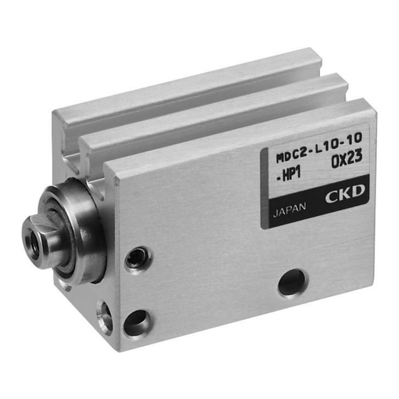
- Page 1 Small direct mounting cylinder MDC2-HP1 Series INSTRUCTION MANUAL 取扱説明書 SM-A42787-A • Read this Instruction Manual before using the product. • Read the safety notes carefully. • Keep this Instruction Manual in a safe and convenient place for future reference.
-
Page 2: Preface
• Since there are a wide variety of customer applications, it is impossible for CKD to be aware of all of them. Depending on the application or usage, the product may not be able to exercise its full performance or an accident may occur due to fluid, piping, or other conditions. -
Page 3: Safety Information
SM-A42787-A SAFETY INFORMATION SAFETY INFORMATION When designing and manufacturing any device incorporating the product, the manufacturer has an obligation to ensure that the device is safe. To that end, make sure that the safety of the machine mechanism of the device, the fluid control circuit, and the electric system that controls such mechanism is ensured. -
Page 4: Precautions On Product Use
• For applications where life or properties may be adversely affected and special safety measures are required. (Exception is made if the customer consults with CKD prior to use and understands the specifications of the product. However, even in that case, safety measures must be taken to avoid danger in case of a possible failure.) -
Page 5: Table Of Contents
SM-A42787-A CONTENTS CONTENTS PREFACE ........................... i SAFETY INFORMATION ....................ii Precautions on Product Use ..................iii Precautions on Product Disposal .................. iii CONTENTS ........................iv PRODUCT OVERVIEW ..................... 1 Model Number Indication ..................1 1.1.1 Product model number ................... 1 Specifications ...................... -
Page 6: Product Overview
1. PRODUCT OVERVIEW 1. PRODUCT OVERVIEW 1.1 Model Number Indication 1.1.1 Product model number ◼ MDC2-HP1 Series Note1: ø4 with switch cannot be selected. Note2: For MDC2 with reed switch, the cylinder cannot be mounted on a magnetic substance (iron plate, etc.). - Page 7 SM-A42787-A 1. PRODUCT OVERVIEW ◼ Stroke length Min. stroke length with two Min. stroke length with one Standard Max. stroke switches (mm) switch (mm) Bore size stroke length length (mm) Proximity Proximity (mm) (mm) Reed switch Reed switch switch switch φ4 -...
-
Page 8: Specifications
SM-A42787-A 1. PRODUCT OVERVIEW 1.2 Specifications 1.2.1 Product specifications Model MDC2-HP1 MDC2-L-HP1 (with switch) Descriptions φ4 φ6 φ8 φ10 Bore size Double acting Actuation Compressed air Working fluid Max. working pressure 0.15 Min. working pressure 1.05 Proof pressure -10 to 60 (no freezing) Note 1 Ambient temperature °C... -
Page 9: Switch Specifications
SM-A42787-A 1. PRODUCT OVERVIEW 1.2.2 Switch specifications Proximity Descriptions 2-wire type 3-wire type F2S/H/V F2YH/V F3S/H/V F3YH/V Applications Only for programmable controller For programmable controller, relay ― Power supply voltage 10 to 28VDC Load voltage 10 to 30VDC 24VDC±10% 30 VDC or less Note 2 Load current 5 to 20mA... -
Page 10: Installation
SM-A42787-A 2. INSTALLATION 2. INSTALLATION 2.1 Environment CAUTION When using the product in a cutting, casting, or welding plant, install a cover to prevent foreign matters such as cutting fluid, chips, powder, and dust from entering. Do not use the equipment in the following environments. •... -
Page 11: Unpacking
SM-A42787-A 2. INSTALLATION 2.2 Unpacking • Check that the model number ordered and the model number indicated on the product are the same. • Check the exterior of the product for any damage. • When storing the product, take proper measures to prevent foreign matters from entering the cylinder. - Page 12 SM-A42787-A 2. INSTALLATION ◼ The maximum sensitivity position (HD,RD),Operating range, Hysteresis (unit:mm) ●Switch mounting position Proximity switch (F2, F3, F2Y, F3Y, F3P) Reed switch (F0) Proximity switch F2S,F3S Lead wire straight (H) Lead wire angled(V) Lead wire straight (H) Lead wire angled(V) ●Switch mounting dimensions Switch mounting Reed switch (F0H/V)
-
Page 13: Changing The Position Of The Switch
SM-A42787-A 2. INSTALLATION 2.3.3 Changing the position of the switch Loosen the fastening screw (set screw). Move the switch body along the groove on the side of the body or the rail plate and then tighten the screw at the predetermined position. 2.3.4 Replacing the switch Loosen the fastening screw (set screw) and remove the switch body from the groove. -
Page 14: Piping
SM-A42787-A 2. INSTALLATION 2.4 Piping WARNING Insert the tube into the fitting until it firmly rests on the tube end and make sure that the tube does not come off before use. • Use pipes that are made of corrosion-resistant materials after the filter such as zinc-plated pipes, nylon tubes, and rubber tubes. - Page 15 SM-A42787-A 2. INSTALLATION ◼ Seal material Use a seal tape or a seal material to stop leakage from piping. Apply a seal tape or seal material to the screw threads leaving two or more threads at the pipe end uncovered or uncoated. If the pipe end is fully covered or coated, a shred of seal tape or residue of seal material may enter inside of the pipes or device and cause a failure.
-
Page 16: Piping Port
SM-A42787-A 2. INSTALLATION 2.4.1 Piping port As compatible piping fittings are limited, refer to the table below to select the fitting. < With wall > Descrip Port position dimensions With wall tions (mm) Port Bore size Fitting O.D. φD size Stroke Applicable fittings Inapplicable fittings... - Page 17 SM-A42787-A 2. INSTALLATION < Without wall > Descrip Port position dimensions (mm) Without wall tions Port Bore size Fitting O.D. φD size Stroke Applicable fittings Inapplicable fittings (mm) GWS4-M3-S SC3W-M3-3 GWS3-M3-S φ7 or less SC3W-M3-4 FTS4-M3 SC3U-M3-3 SC3U-M3-4 φ4 GWS3-M3-S GWS4-M3-S FTS4-M3 φ10 or less...
-
Page 18: Wiring
SM-A42787-A 2. INSTALLATION 2.5 Wiring 2.5.1 Proximity switch ◼ Connection of lead wires Turn off the power to the device in the electric circuit to which the switch is to be connected and connect the lead wires according to their color. Not turning off the power may cause damage to the electric circuit of the switch load. - Page 19 SM-A42787-A 2. INSTALLATION ◼ Protection of the output circuit For the following cases, refer to the figures below and install a protection circuit: • When an inductive load (relay or solenoid valve) is connected and used: See Ex. 1 Use a surge absorption element since a surge voltage is generated when the switch is turned off. •...
- Page 20 SM-A42787-A 2. INSTALLATION ◼ Connection to the programmable controller The connection method depends on the type of the programmable controller. Connect as shown below. Programmable controller Programmable controller Blue Brown Blue Brown Switch Switch Input Input termi- termi- nals nals Blue Brown Blue...
-
Page 21: Reed Switch
SM-A42787-A 2. INSTALLATION 2.5.2 Reed switch ◼ Connection of lead wires Do not connect the lead wire of the switch to the power directly. Make sure that the lead wire and the load are connected in serial. For F0 switches, observe the following instructions as well: •... - Page 22 SM-A42787-A 2. INSTALLATION ◼ Contact capacity Do not use a load that exceeds the maximum contact capacity of the switch. If the current falls below the rated current value, the indicator may not light up. ◼ Relay Use one of the following or equivalent relays: •...
-
Page 23: Usage
SM-A42787-A 3. USAGE 3. USAGE 3.1 Using the Cylinder ◼ Working pressure range Use the cylinder within the following pressure range: Model Pressure range (MPa) Bore size(mm) φ4 0.2 to 0.7 φ6,φ8 MDC2-HP1 0.15 to 0.7 φ10 0.1 to 0.7 ◼... -
Page 24: Using The Switch
SM-A42787-A 3. USAGE 3.2 Using the Switch WARNING When using MDC2 with reed switch, the cylinder cannot be mounted on a magnetic substance (iron plate, etc.). For MDC2 with proximity switch, use the cylinder at ambient temperature of 40°C or less. Failure to do so could lead to switch detection malfunction. -
Page 25: Maintenance And Inspection
SM-A42787-A 4. MAINTENANCE AND INSPECTION 4. MAINTENANCE AND INSPECTION WARNING Do not disassemble the product. Do not touch electrical wiring connections (bare live parts) of actuators equipped with switches, and other such actuators. Do not touch live parts with bare hands. An electric shock may occur. -
Page 26: Periodic Inspection
SM-A42787-A 4. MAINTENANCE AND INSPECTION 4.1 Periodic Inspection In order to use the product under optimum conditions, perform a periodic inspection once or twice a year. 4.1.1 Inspection item • Actuation state • Change in the piston speed and cycle time •... -
Page 27: Internal Structural Diagram
SM-A42787-A 4. MAINTENANCE AND INSPECTION 4.1.4 Internal structural diagram ●MDC2-4(Double acting single rod) ●MDC2-L-6,8,10(Double acting single rod/with switch) ●MDC2-6,8,10(Double acting single rod) 2020-12-14... - Page 28 SM-A42787-A 4. MAINTENANCE AND INSPECTION Parts list Part name Material Remarks Piston Stainless steel Bush Oil-impregnated copper alloy Rod packing Nitrile rubber φ4:Phosphor bronze Rod metal φ6 to φ10:Stainless steel Cylinder body Aluminum alloy Hard alumite Piston packing Magnet Plastic E type snap ring Stainless steel Hexagon socket set screw...
-
Page 29: Troubleshooting
SM-A42787-A 5. TROUBLESHOOTING 5. TROUBLESHOOTING 5.1 Problems, Causes, and Solutions If the product does not operate properly, check the table below for a possible solution. 5.1.1 Cylinder Problem Cause Solution No pressure or insufficient pressure is applied. Secure sufficient pressure. No signal is input to directional control valve. -
Page 30: Switch
Ambient temperature is too high or too low. to 60°C. Magnetic field is nearby. Install a magnetic shield. External signal is faulty. Check the external circuit. If you have any other questions or concerns, contact your nearest CKD sales office or distributor. 2020-12-14... -
Page 31: Warranty Provisions
If the product specified herein fails for reasons attributable to CKD within the warranty period specified below, CKD will promptly provide a replacement for the faulty product or a part thereof or repair the faulty product at one of CKD’s facilities free of charge.
Need help?
Do you have a question about the MDC2-HP1 Series and is the answer not in the manual?
Questions and answers