Table of Contents
Advertisement
Quick Links
Advertisement
Table of Contents

Subscribe to Our Youtube Channel
Related Manuals for EK Quantum Scalar2 Direct Link Side Port Terminal - Acetal


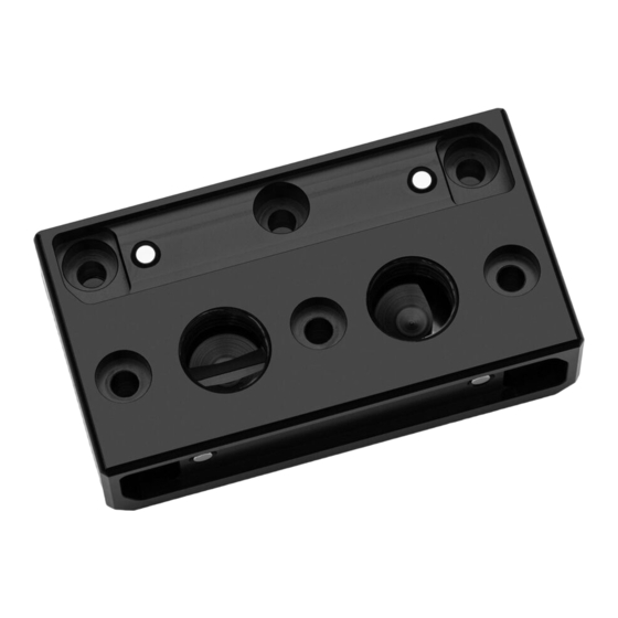
Summary of Contents for EK Quantum Scalar2 Direct Link Side Port Terminal - Acetal
- Page 1 EK-Quantum Scalar Direct Link Side Port Terminal – Acetal USER GUIDE...
- Page 2 GPU or its circuit board (PCB). The EK Fittings require only a small amount of force to screw them firmly in place since the liquid seal is ensured by the rubber O-ring gaskets.
-
Page 3: Table Of Contents
TABLE OF CONTENTS BOX CONTENTS PRODUCT DIMENSIONS TECHNICAL SPECIFICATIONS AND MAIN PARTS INSTALLING THE EK-Quantum Scalar Direct Link Side Port Terminal FITTINGS AND TUBING TESTING THE LOOP WARRANTY SUPPORT AND SERVICE SOCIAL MEDIA - 3 -... -
Page 4: Box Contents
BOX CONTENTS Screw M4 x 16 DIN7984 (3 pcs) EK-Quantum Scalar Direct Link Side Port Terminal – Acetal - 4 -... -
Page 5: Product Dimensions
PRODUCT DIMENSIONS 72 mm 50 mm 19 mm 22 mm 16 mm 7 mm 36 mm 65 mm - 5 -... -
Page 6: Technical Specifications And Main Parts
Disc magnet 3 x 3 8208 Screw M3 x 8 7991DIN 5008 OR 52 x 1.5 mm INSTALLING THE EK-Quantum Scalar Direct Link Side Port Terminal DO NOT REMOVE Important! Before starting, make sure to have a clean, flat surface TWO (2) MARKED to work on. - Page 7 STEP 2 From the FC terminal, unscrew two (2) M3 x 10 DIN7991 Screws SIDE COVER and detach the side cover. M3 x 10 DIN7991 SCREW FC TERMINAL Reuse the side cover and M3 x 10 DIN7991 Screws and tighten them on the replacement (side) terminal.
- Page 8 STEP 3 Place two (2) Terminal O-rings into the terminal slots and position the replacement terminal assembly on the water block. During this process, make sure you have aligned the holes. Secure the terminal with three (3) M4 x 16 DIN7984 and M4 x 20 DIN7984 Screws.
-
Page 9: Fittings And Tubing
STEP 1 TESTING THE LOOP To make sure the installation of EK components was successful, we recommend you perform a leak test for 24 hours. When your loop is complete and filled with coolant, connect the pump to a PSU outside of your system. -
Page 10: Warranty
Removing the label will void the leak-free guarantee, but not the guarantee on the product itself. Any other RMA issues can be reported to EK Customer Support at www.ekwb.com/support for further analysis. -
Page 11: Support And Service
SUPPORT AND SERVICE In case you need assistance or wish to order spare parts or a new mounting mechanism, please contact: https://www.ekwb.com/customer-support/ For spare parts orders, refer to the page with “TECHNICAL SPECIFICATIONS AND MAIN PARTS” where you can find the EAN number of each part you might need.
Need help?
Do you have a question about the Quantum Scalar2 Direct Link Side Port Terminal - Acetal and is the answer not in the manual?
Questions and answers