Table of Contents
Advertisement
Advertisement
Table of Contents

Subscribe to Our Youtube Channel
Related Manuals for EK Quantum PC-O11D XL D5 PWM D-RGB


Summary of Contents for EK Quantum PC-O11D XL D5 PWM D-RGB
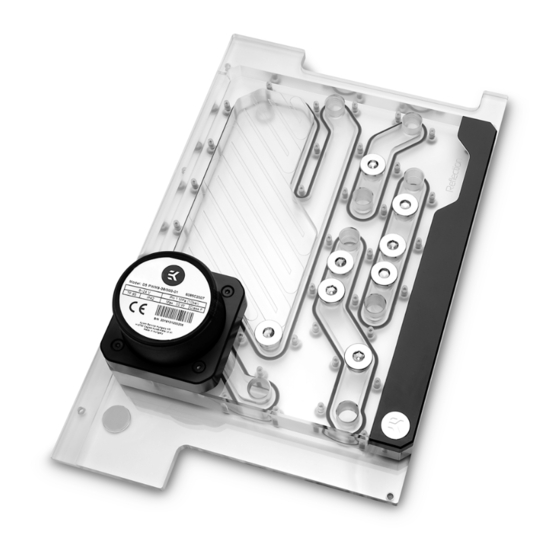
- Page 1 EK-Quantum Reflection PC-O11D XL D5 PWM D-RGB DISTRIBUTION PLATE USER GUIDE...
- Page 2 Before you start using this product please follow these basic guidelines: Please carefully read the manual before beginning with the installation process! The EK Fittings require only a small amount of force to screw them firmly in place since the liquid seal is ensured by the rubber O-ring gaskets.
-
Page 3: Table Of Contents
TABLE OF CONTENT BOX CONTENTS PREPARING THE 011D XL CHASSIS INSTALLING THE DISTRIBUTION PLATE IN THE 011D XL RECOMMENDED DISTRIBUTION PLATE CONFIGURATIONS CONNECTING THE D-RGB LED STRIP CONNECTING THE PUMP TESTING THE LOOP SUPPORT AND SERVICE SOCIAL MEDIA - 3 -... -
Page 4: Box Contents
BOX CONTENTS Front mounting Bracket (1 pc) M3x6 DIN7380 (2 pcs) M3x8 DIN7991 (5 pcs) M3 Nut (2 pcs) EK-Quantum Reflection PC-O11D XL D5 PWM D-RGB Allen Key 2mm (1 pc) EK-Loop Multi Allen Key - 4 -... -
Page 5: Preparing The 011D Xl Chassis
PREPARING THE 011D XL CHASSIS Before installing the distribution plate, carefully read the PC case manual. STEP 1 Unscrew the factory provided screws and remove the top panel from the case. STEP 1 STEP 2 Remove both side panels and the front panel from the case. STEP 2 - 5 -... - Page 6 STEP 3 The SSD Trays also need to be removed from the back side of the chassis. Once the distribution plate is secured they can be reinstalled as required. STEP 3 STEP 4 For easier installation of the distribution plate, you should remove the Fan/SSD Tray from the bottom of the case.
-
Page 7: Installing The Distribution Plate In The 011D Xl
INSTALLING THE DISTRIBUTION PLATE IN THE 011D XL STEP 1 Carefully place the EK-Quantum Reflection PC-O11D XL D5 PWM D-RGB distribution plate into the PC case and align the mounting holes at the back. STEP 1 DETAIL VIEW STEP 2 Secure the distribution plate to the chassis with two (2) M3 x 6 DIN7380 and M3 nuts (as shown in the diagram). - Page 8 STEP 3 Position the front mounting bracket onto the distribution plate and secure it with five(5) M3 X 8 DIN7991 mounting screws. M3 X 8 DIN7991 Front mounting Bracket DETAIL VIEW M3 X 8 DIN7991 Front mounting Bracket STEP 3 - 8 -...
-
Page 9: Recommended Distribution Plate Configurations
TOP RADIATOR OUTLET All remaining unused ports must be closed with supplied plugs, CPU OUTLET using the EK-Loop Multi Allen Key (6, 8, 9 mm). CPU INLET FILL Only one INLET and one OUTLET port for the GPU connection can be used, while all other INLET and OUTLET GPU ports must be closed with G1/4 plugs (enclosed in the package). - Page 10 FILL (exterior) DRAIN (exterior) - 10 -...
-
Page 11: Connecting The D-Rgb Led Strip
D-RGB Header RGB Header CONNECTING THE PUMP The EK-D5 PWM pump has two connectors. 1. 4-pin Molex: It must be connected directly to your PSU at all times as it is used to power the pump. 2. 4-pin PWM fan: It can be connected to your motherboard’s CPU_ Fan or designated water pump header. -
Page 12: Testing The Loop
TESTING THE LOOP To make sure the installation of EK components was successful, we recommend you perform a leak test for 24 hours. When your loop is complete and filled with coolant, connect the pump to a PSU outside of your system. Do not connect power to any of the other components. -
Page 13: Support And Service
SUPPORT AND SERVICE For assistance please contact: http://support.ekwb.com/ EKWB d.o.o. Pod lipami 18 1218 Komenda Slovenia - EU SOCIAL MEDIA EKWaterBlocks @EKWaterBlocks ekwaterblocks EKWBofficial ekwaterblocks...
Need help?
Do you have a question about the Quantum PC-O11D XL D5 PWM D-RGB and is the answer not in the manual?
Questions and answers