Table of Contents
Advertisement
Advertisement
Table of Contents

Related Manuals for Lowrance ActiveTarget 2


Summary of Contents for Lowrance ActiveTarget 2
- Page 1 ActiveTarget ® Installation Manual English www.lowrance.com Scan for more info...
- Page 2 Navico Holding AS and other entities. • Navico is a trademark of Navico Holding AS. ® • Lowrance is a trademark of Navico Holding AS. ® • ActiveTarget 2 is a trademark of Navico Holding AS. ®...
-
Page 3: Table Of Contents
CONTENTS 4 Introduction 4 Parts included 6 Sonar module installation 6 Choose location 6 Mount sonar module 7 Transducer installation: single view 7 Shaft mounting 8 Down, forward or scout view 10 Motor mounting 10 Down or forward view 11 Scout view 11 Transom mounting 12 Transducer installation: dual views 12 Forward and scout view 14 180°... -
Page 4: Introduction
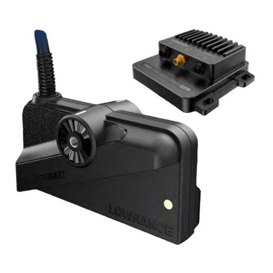
INTRODUCTION ActiveTarget 2 is the next-generation ActiveTarget live sonar, offering improved, single- view images of fish locations around your boat. In addition, if connected to a Lowrance HDS Pro multi-function display, you can install two ActiveTarget 2 systems and view simultaneous dual images without transducer interference. - Page 5 A Transducer B Sonar module C Sonar module mounting screw, 4x D M4 sonar module grounding screw E Power cable F Ethernet cable Shaft mount clamp (pre-assembled) G M6x20 cap screw, 4x H Shaft back collar Rubber shaft collar insert, 2x J Shaft front collar K M6 nut, 4x L Shaft mount bracket arm...
-
Page 6: Sonar Module Installation
SONAR MODULE INSTALLATION WARNING: Always wear appropriate eye wear, ear protection and dust mask ⚠ when drilling, cutting, or sanding. Remember to check the reverse side of all surfaces whenever drilling or cutting. Choose location Choose a mounting location carefully. Make sure there are no hidden electrical wires or other parts behind the panel before you drill or cut. -
Page 7: Transducer Installation: Single View
TRANSDUCER INSTALLATION: SINGLE VIEW You can mount the transducer to the shaft or motor of your trolling motor to achieve three possible views: • Down. Use for vertical fishing to see what is below the transducer. Watch your lure and fish movements in real-time. •... -
Page 8: Down, Forward Or Scout View
Down, forward or scout view Use one knob and washer to attach the short side of the bracket arm to the shaft front collar. Align the lines on the arm with the lines on the collar to achieve the desired view. ¼... - Page 9 WARNING: Tighten the screws by hand and not electric drill. Tighten them just ⚠ enough to prevent movement under normal use. Do not use any type of thread- locking compound on the cap screws or nuts as it may degrade the quality of the bracket and cause it to break.
-
Page 10: Motor Mounting
Motor mounting A transducer mounted to the trolling motor can be positioned for all three views: Down Forward Scout Down and forward views can be achieved on the port or starboard side of the motor: Port Starboard Down or forward view Use the shoulder bolt, M8 metal washer then rubber washer to attach the down/forward mounting bracket to the transducer. -
Page 11: Scout View
Transom mounting If you don’t have a trolling motor on your vessel, you can install a single ActiveTarget 2 on the transom. A transom bracket is sold as a separate accessory and allows a transducer to be oriented in down or forward view. -
Page 12: Transducer Installation: Dual Views
To view two sonar images on your multi-function display (MFD), you can install two ActiveTarget 2 systems (two sonar modules and two transducers) on your boat. The sonar modules are synchronized using the blue wire in the power cable and run simultaneously without interference between them. - Page 13 To attach both forward and scout transducers on the motor, prepare a transducer for each view by following the instructions in the “Motor mounting” section of this manual. Then use a single hose clamp to attach both assemblies to the motor. Align the mounting brackets to the motor just as you would in a single-view installation.
-
Page 14: 180° View
180° view 180° view (composite forward and back) is achieved by installing: • both the forward and back transducers on the shaft • the forward transducer on the shaft and back transducer on the motor. To achieve the 180° view with two transducers on the shaft, attach one shaft mount clamp with transducer in forward (starboard) view and the other in forward (port) view. -
Page 15: Scout Wide View
The scout wide bracket is sold as a separate accessory and holds two ActiveTarget 2 transducers at proper scout angles. For mounting instructions, see the ActiveTarget 2 Scout Wide Bracket Installation... -
Page 16: Wiring
WIRING WARNING: Before starting the wiring, turn the electrical power off. If power is left ⚠ on or turned on while wiring, fire, electrical shock or other serious injury may occur. Make sure the power supply voltage is compatible with the unit. Do not: •... -
Page 17: Connect Transducer
Wiring diagram for a dual-view system: Grounding Ethernet Ethernet ¼ Note: For alternative ways to connect the yellow wire, refer to page 18. Connect transducer Connect the transducer cable to the SONAR port of the sonar module. Securely support the cable with cable ties. WARNING: Leave enough slack in the cable so you can adjust the transducer to all ⚠... - Page 18 Power controlled by external switch To turn the sonar module ON/OFF when power is applied/removed by an external switch, connect the yellow wire to the red wire via a switch after the fuse. Description Color Synchronization wire (used Blue only in dual view systems) Accessory wake up Yellow + 12/24 V DC...
-
Page 19: Ground Sonar Module
Ground sonar module You can earth-ground the sonar module using the terminal on the top of the case. This terminal is DC isolated from power to eliminate the risk of galvanic corrosion. For installations that suffer from noise issues, the grounding terminal allows you to connect to various possible ground points. -
Page 20: Dimensions
DIMENSIONS Sonar module 219.3 mm (8.63”) 197.3 mm (7.76”) 115.48 mm 192.1 mm (4.54”) (7.56”) 175.1 mm (6.89”) 72.9 mm (2.86”) -
Page 21: Transducer
Transducer 7.62 m (25 ft) 82.4 mm (3.24”) 149.8 mm 58.0 mm (5.90”) (2.28”) -
Page 22: Technical Specifications
TECHNICAL SPECIFICATIONS Sonar module Environmental Storage temperature -30°C to 70°C (-22°F to 158°F) Operating temperature -15°C to 55°C (5°F to 131°F) IP class IP67 Electrical Power supply 12/24 V DC Operating voltage 10.8 V DC - 31.2 V DC Current drain (maximum) 1.5A at 13.8 V Reverse polarity protection Fuse rating... - Page 24 ®Reg. U.S. Pat. & Tm. Off, and ™ common law marks. www.lowrance.com Visit www.navico.com/intellectual-property to review the global trademark rights and accreditations for Navico Holding AS and other entities.
Need help?
Do you have a question about the ActiveTarget 2 and is the answer not in the manual?
Questions and answers