
Related Manuals for Lowrance HDS12 Live


Summary of Contents for Lowrance HDS12 Live
- Page 1 Live ® Operator manual ENGLISH Software version 23.3 Scan here www.lowrance.com to save a copy...
- Page 3 Preface Disclaimer Warning: Refer to important safety information in the user app guides, product documentation and review all warnings, limitations, and disclaimers before using this product. This product is not a substitute for proper training and prudent seamanship. It is the owner’s sole responsibility to install and use the equipment in a manner that will not cause accidents, personal injury or property damage.
- Page 4 Apple, Inc. Link™ is a trademark of Navico Group. Live™ is a trademark of Navico Group. Lowrance® is a trademark of Navico Group. Mercury® is a trademark of Brunswick Corporation. microSD® is a trademark of SD-3C, LLC.
- Page 5 Brunswick Corporation. Warranty The warranty card is supplied as a separate document. In case of any queries, refer to the brand website of your unit or system: www.lowrance.com Compliance statements Europe Hereby, Navico Group declares that the radio equipment complies with CE under RED Directive 2014/53/EU.
- Page 6 Declaration of conformity is available in the product's section at the following website: • www.lowrance.com United States of America This device complies with Part 15 of the FCC Rules. Operation is subject to the following two conditions: (1) this device may not...
- Page 7 Warning: The user is cautioned that any changes or modifications not expressly approved by the party responsible for compliance could void the user’s authority to operate the equipment. Ú Note: This equipment generates, uses and can radiate radio frequency energy and, if not installed and used in accordance with the instructions, may cause harmful interference to radio communications.
- Page 8 The latest available manual version can be downloaded from the following website: • www.lowrance.com Viewing the manual on the screen The PDF viewer included in the unit makes it possible to read the manuals and other PDF files on the screen.
- Page 9 Preface | HDS Live Operator Manual...
- Page 10 Preface | HDS Live Operator Manual...
-
Page 11: Table Of Contents
Contents 19 Introduction The front panel keys Card reader Feature unlock Device registration Lowrance mobile app 23 The user interface The Home page Multiple panel pages Application pages System controls dialog 27 Basic operation Removing the suncover Turning the system on and off... - Page 12 Panning the chart Chart orientation Look ahead Displaying information about chart items Using the cursor on the panel Find objects on chart panels Color trails 3D charts Chart overlay C-MAP charts Navionics® charts Chart settings 58 Waypoints, routes, and trails Waypoints, Routes, and Trails dialogs Waypoints Routes...
- Page 13 88 SideScan About SideScan The SideScan panel Zooming the image Using the cursor on the panel Viewing history Recording SideScan data Setting up the image Advanced options More options 93 DownScan About DownScan The DownScan panel Zooming the image Using the cursor on the panel Viewing DownScan history Recording DownScan data Setting up the DownScan image...
- Page 14 111 ActiveTarget 111 About ActiveTarget 111 ActiveTarget forward panel 112 ActiveTarget down panel 113 ActiveTarget scout panel 113 Zooming the image 113 Stopping the Sonar 114 Using the cursor on the panel 114 Recording ActiveTarget video 114 Modes and image settings 116 More options 118 ActiveTarget 2 118 About ActiveTarget 2...
- Page 15 130 Autopilot indication 130 Autopilot modes 134 Trolling motor speed control 134 Recording and saving a trail 135 Autopilot settings 139 Outboard autopilot 139 Safe operation with the autopilot 139 Selecting active autopilot 140 The autopilot controller for outboard motors 141 Engaging and disengaging the autopilot 141 Autopilot indication 141 Autopilot modes...
- Page 16 174 Radar target symbols 175 Dangerous targets 176 MARPA targets 180 Radar settings 184 Audio 184 About the audio function 184 The audio controller 185 Setting up the audio system 185 Selecting audio source 186 Using an AM/FM radio 186 Navico WM-4 marine satellite receiver support 187 Sirius radio 188 Viewing DVD video 189 AIS...
- Page 17 207 Dual mode Wi-Fi® 208 Lowrance mobile app 208 Connecting via a hotspot 209 Connecting to an MFD acting as an access point 209 Managing Wi-Fi® connected remotes 210 LR-1 Remote controller 212 Using your phone with the MFD 212 About phone integration...
- Page 18 233 Integration of 3 party devices 233 SmartCraft VesselView integration 233 FLIR® camera control 235 Suzuki® engine integration 236 Yamaha® engine integration 236 BRP® engine integration 237 FUSION-Link™ integration 237 BEP® CZone® integration 239 Power-Pole® anchors 241 ITC lighting 243 NMEA 2000® RGBW lighting Contents | HDS Live Operator Manual...
-
Page 19: Introduction
Introduction The front panel keys Pages key • Press once to activate the Home page. Repeat short presses to cycle the favorite buttons Press and hold is configurable. Refer to "Configuring the quick • access keys" on page 35 Waypoint key •... -
Page 20: Card Reader
Enter key • Press to select or save your settings Zoom keys and MOB key • Zoom keys for panels and images • Simultaneous pressing both keys saves a Man Overboard (MOB) waypoint at the current vessel position Menu key •... -
Page 21: Feature Unlock
Connect and Register option in the system settings dialog or system controls dialog. Lowrance mobile app You can download the Lowrance: Fishing & Navigation app from the Apple® App Store® and Google Play® stores. Ú Note: The mobile app is an optional offering and will not affect the normal operation of your display unit. - Page 22 description to check the app's compatibility with your mobile device. Once connected, you can use the app to: • Register your display unit. • View and download product documentation. • Create and synchronize waypoints, routes, and tracks. • Explore points of interest (POI). •...
-
Page 23: The User Interface
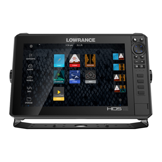
The user interface The Home page The Home page is accessed from any operation by a short press on the home key. Settings button Opens the settings dialog. Use it to configure the system. Applications Select a button to display the application as a full page panel. -
Page 24: Multiple Panel Pages
Multiple panel pages Panel sizes in a multiple panel page can be adjusted from the System Controls dialog. Refer to "Adjusting the split on multiple panel pages" on page 33. In a multiple panel page, only one panel can be active at a time. The active panel is outlined with a border. -
Page 25: System Controls Dialog
Predefined split pages A predefined split page shows more than one application page on a panel. You can adjust the split on a predefined split page. Refer to "Adjusting the split on multiple panel pages" on page 33. Favorites bar The favorites bar lists preconfigured pages and favorite pages you have made. - Page 26 The user interface | HDS Live Operator Manual...
-
Page 27: Basic Operation
Basic operation Removing the suncover The protective suncover of your MFD is designed to have a tight fit and must be carefully removed to avoid damaging the MFD or the cover. To remove the suncover, hold the edges from the slots located on the sides of the cover, and use your thumbs to gently press the center of the cover before lifting the cover. -
Page 28: Display Illumination
Switch from Standby mode to normal operation by a short press on the Power key. Display illumination Brightness You can cycle the preset backlight levels by short presses on the Power key. The display backlighting can also be adjusted from the System Controls dialog. -
Page 29: Man Overboard Waypoint
To return to previous menu level: • Select the back menu option • Press the exit key To hide a panel menu: • Swipe the menu to the right • On menu level one press the exit key Man Overboard waypoint If an emergency situation should occur, you can save a Man Overboard (MOB) waypoint at the vessel’s current position. -
Page 30: Locking The Touchscreen
Locking the touchscreen You can temporarily lock the touchscreen to prevent accidental operation of the system. You lock the touchscreen from the System Controls dialog. You remove the lock function by pressing and holding the power key. Single Sign-On Use the Single Sign-On (SSO) authentication method to log on to your app account and automatically gain secure access without having to enter your login credentials via the multi-function display (MFD). -
Page 31: Screen Capture
MFD, and your user ID is displayed on the My Lowrance account page. To log out, go to Settings > Services > My Lowrance account, and select Log out. You can also access Synchronize my data from the System controls dialog. - Page 32 Screen captures are saved to internal memory. Basic operation | HDS Live Operator Manual...
-
Page 33: Customizing Your System
Customizing your system Customizing the Home page wallpaper The Home page's wallpaper can be customized. You can select one of the pictures included with the system, or you can use your own picture in .jpg or .png format. The images can be available on any location that can be seen in the files browser. -
Page 34: Data Overlay
Data overlay You can have data information as overlay on chart and sonar pages. The data overlay is set individually for each default page, favorite pages and for the predefined split pages. The information can be any data available on the network. You turn overlay data on or off from the system controls dialog. -
Page 35: Configuring The Quick Access Keys
Save the page layout. The system displays the new favorite page, and the new page is included in the list of favorite pages on the Home page. Edit favorite pages Select the edit icon in the favorite panel: - Select the X icon on a favorite icon to remove the page - Select the tool icon on a favorite icon to display the page editor dialog Add or remove panels in the page editor dialog... -
Page 36: Enabling Or Disabling Features
Select a configuration from the drop-down list for each of the keys you want to configure. Enabling or disabling features A compatible device connected to the unit should automatically be identified by the system. If not, enable the feature from the advanced settings dialog. -
Page 37: Charts
Charts The Chart panel North indicator Vessel Chart range scale Grid lines* Range rings* * Optional chart items. Optional chart items can be turned on/off individually from the chart settings dialog. Chart data The system can be delivered with preloaded cartography. For a full selection of supported charts, visit the product web site. -
Page 38: Selecting Chart Source
will be displayed until you re-insert the card or manually switch back to the preloaded cartography. Selecting chart source Available chart sources are listed in the menu. If you have identical chart sources available, the system automatically selects the chart with most chart details for your displayed region. -
Page 39: Chart Orientation
Chart orientation You can specify how the chart is rotated in the panel. North up Displays the chart with north upward. Heading up Displays the chart with the vessel’s heading (A) directed upward. Heading information is received from a compass. If heading is not available, then the COG from the GPS is used. -
Page 40: Look Ahead
Look ahead Moves the vessel icon on the panel to maximize your view ahead of the vessel. Displaying information about chart items When you select a chart item, a waypoint, a route, or a target, basic information for the selected item is displayed. Select the chart item's pop-up to display all available information for that item. -
Page 41: Find Objects On Chart Panels
The cursor assist function The cursor assist function allows for fine tuning and precision placement of the cursor without covering details with your finger. Activate the cursor on the panel, then press and hold your finger on the screen to switch the cursor symbol to a selection circle, appearing above your finger. -
Page 42: Color Trails
Activate the cursor on the panel to search from the cursor position. If the cursor is not active, the system searches for items from the vessel's position. Ú Note: You must have a SiriusXM® Marine subscription to search for fueling stations. Ú... -
Page 43: Chart Overlay
Panning the 3D chart You can move the chart in any direction by selecting the Pan icon and then panning in the desired direction. To return the chart to vessel position use the return to vessel option. Chart overlay You can add overlays on the chart panel. When an overlay is selected, the chart menu expands to include basic menu options for the selected overlay. - Page 44 Deletes all heat map data gathered up to the moment it is selected. Heat map data is automatically deleted when the unit is turned off. Genesis live overlay Ú Note: Only available when viewing Lowrance or C-MAP chart source. Ú Note: A microSD™ memory card with available space must be inserted into the unit before data can be recorded.
- Page 45 Genesis live menu options Transparency Adjusts the transparency of the overlay. Contour interval Defines the density of live depth contours shown. Depth palette Controls the color palette used to color the depth areas. • Chart sync – syncs the Genesis live layer to the same palette as the chart depth palette defined in the chart menu (under Chart options, View, Depth palette).
-
Page 46: Map Charts
Selecting radar overlay source on chart panels To select the radar source of the radar overlay displayed on the chart panel, use source menu option. This option is available under Radar options when radar is selected as the overlay. For chart pages with more than one chart with radar overlay, it is possible to set up different radars sources for each chart panel. - Page 47 Static Current and Tide icons Dynamic Current icons C-MAP specific chart options Photo overlay Photo overlay enables you to view satellite photo images of an area as an overlay on the chart. The availability of such photos is limited to certain regions, and cartography versions. You can view photo overlays in either 2D or 3D modes.
- Page 48 Minimum transparency Transparency at 80 Raster charts Changes the view to that of a traditional paper chart. Raster transparency Controls the transparency of raster imagery. High resolution bathymetry Enables and disables higher concentration of contour lines. Chart detail • Full - displays all available information for the chart in use. •...
- Page 49 Depth palette Controls the Depth palette used on the map. Depth filter Filters out depth values shallower than the selected depth filter limit. Safety depth Charts use different shades of colors to distinguish between shallow and deep water. After enabling the safety shading depth palette, specify the desired safety depth limit and the color/shading for different depths.
-
Page 50: Navionics® Charts
3D exaggeration Graphical settings that are available in 3D mode only. Exaggeration is a multiplier applied to the drawn height of hills on land, and troughs in water to make them look taller or deeper. Ú Note: This option is grayed out if the data is not available in the map card inserted. - Page 51 Photo transparency The Photo transparency sets the opaqueness of the photo overlay. With minimum transparency settings the chart details are almost hidden by the photo. Minimum transparency Maximum transparency Chart shading Shading adds terrain information to the chart. Fishing range Select a range of depths between which Navionics®...
- Page 52 No shallow water highlighted Shallow water highlight: 0 m - 3 m Safety depth The Navionics® charts use different shades of blue to distinguish between shallow and deep water. Safety depth, based on a selected limit, is drawn without blue shading.
- Page 53 Transparency The SonarChart Live overlay is drawn on top of other chart data. The chart data is completely covered at minimum transparency. Adjust the transparency to allow the chart details to be seen. Minimum depth Adjusts what SonarChart Live rendering treats as the safety depth. This affects the coloring of the SonarChart Live area.
- Page 54 The following icons and symbology are used: Current speed The arrow length depends on the rate, and the symbol is rotated according to flow direction. Flow rate is shown inside the arrow symbol. The red symbol is used when current speed is increasing, and the blue symbol is used when current speed is decreasing.
-
Page 55: Chart Settings
Chart settings The options in the chart settings dialog depends on which chart source is selected in the system. 3D boat selection Determines which icon to use on 3D charts. Range rings The range rings can be used to present the distance from your vessel to other panel objects. - Page 56 The length of the extension line is either set as a fixed distance, or to indicate the distance the vessel moves in the selected time period. If no options are turned on for the vessel then no extension lines are shown.
- Page 57 Waypoints, Routes, Trails Opens the Waypoints, Routes, and Trails dialog where these items can be created, edited, deleted, and searched. Charts | HDS Live Operator Manual...
-
Page 58: Waypoints, Routes, And Trails
Waypoints, routes, and trails Waypoints, Routes, and Trails dialogs These dialogs give access to advanced edit functions and settings for these items. Waypoints A waypoint is a user generated mark positioned on a chart, on a radar image or on the Sonar image. Each waypoint has an exact position with latitude and longitude coordinates. - Page 59 New Waypoint icon When selected, the dialog with waypoint symbol alternatives is displayed. Selecting a waypoint symbol creates the waypoint at cursor or vessel position with the selected symbol. This mode is persistent, the next time you create a new waypoint the same dialog opens and if you select a symbol a waypoint is created with the symbol.
-
Page 60: Routes
Delete a waypoint You can delete a waypoint from the Edit Waypoint dialog or by selecting the Delete menu option when the waypoint is activated. You can also delete waypoints from the Waypoints tool on the Home page. You can delete MOB waypoints the same way. Waypoint alarm settings You can set an alarm radius for each individual waypoint you create. - Page 61 Creating a new route on the chart panel Activate the cursor on the chart panel Select the new route option from the menu Position the first waypoint on the chart panel Continue positioning new routepoints on the chart panel until the route is completed Save the route by selecting the save option in the menu.
- Page 62 Converting trails to routes You can convert a trail to a route from the Edit Trail dialog. The dialog is activated by activating the trail, then selecting the trail's pop-up, or the Trail menu option. The Edit Trail dialog can also be accessed by selecting the Waypoints tool on the Home page, then the trail tab and then selecting the trail in the Trail dialog.
- Page 63 Ú Note: If no compatible cartography is available, the Dock-to- dock Autorouting or Easy Routing menu option is not available. Compatible cartography includes C-MAP MAX-N+, C-MAP Discover, C-MAP Reveal, Navionics+, and Navionics Platinum. For a full selection of available charts, visit www.c-map.com or www.navionics.com.
- Page 64 • Selection option used for autorouting part of a route. Two routepoints selected Result after automatic routing The edit route dialog You can manage routes and routepoints, and change route properties using the Edit Route dialog. This dialog is activated by selecting an active route's pop-up or from the menu by selecting the route then the details option.
-
Page 65: About Trails
About trails Trails are a graphical presentation of the historical path of the vessel. They allow for retracing where your boat has travelled. Trails can be converted to routes from the edit dialog. From the factory, the system is set to automatically track and draw the vessel's movement on the chart panel. - Page 66 Trails settings Trails are made up of a series of points connected by line segments whose length depends on the frequency of the recording. You can select to position trail points based on time settings, distance, or by letting the system position a trail point automatically when a course change is registered.
-
Page 67: Synchronize My Data
Controls dialog or the Services settings dialog. Using the synchronize feature You can use a browser to sign-in at https://appchart.lowrance.com or you can sign-in to your LOWRANCE® app account from your mobile device or tablet to manage (create new, change, move, and delete): •... - Page 68 • To synchronize, the unit must be connected to the internet. Synchronizing To synchronize the MFD data and your LOWRANCE® app account data (includes your data at https://appchart.lowrance.com), open the Synchronize my data feature from the System Controls dialog or the Services settings dialog.
-
Page 69: Navigating
Navigating About navigating The navigation function included in the system allows you to navigate to the cursor position, to a waypoint, or along a predefined route. For information about positioning waypoints and creating routes, refer to "Waypoints, routes, and trails" on page 58. Steer panel The Steer panel can be used to display information when you are navigating. -
Page 70: Navigate To Cursor Position
Vessel symbol Indicates distance and bearing relative to the intended course. If the XTE (Cross Track Error) exceeds the defined XTE limit, this is indicated with a red arrow including the distance from the track line. Refer to "XTE limit" on page 72. Navigate to cursor position You can start navigating to a cursor position on any chart, radar, or sonar panel. -
Page 71: Navigating With The Autopilot
• Selecting the waypoint tool from the home page and then selecting the routes tab • Selecting the route details option from the menu Navigating with the autopilot When you start navigation on a system with autopilot functionality, you are prompted to set the autopilot to navigation mode. If you choose not to engage the autopilot, the autopilot can be set to navigation mode from the Autopilot Controller later on. -
Page 72: Navigation Settings
Navigation settings Arrival radius Sets an invisible circle around the destination waypoint. The vessel is considered arrived at the waypoint when it is within this radius. XTE limit XTE alarm (Cross track error) Turns on/off the XTE alarm. Trails Opens the Trails dialog where trails settings can be adjusted and trails can be converted into routes for navigation. - Page 73 • Time - select the Time field and enter the time you want to record. Phantom Loran Enables use of Phantom Loran positioning system. Loran settings Defines Loran chains (GRI) and preferred station for waypoint entry, cursor position and position panel. The graphic example shows a cursor position window with Loran position information.
-
Page 74: Sonar
Sonar The image Fish arches History preview* Temperature graph* Depth at cursor Amplitude scope* Zoom (range) buttons Water depth and Water temperature at cursor location Range scale Bottom * Optional items that you can turn on/off individually. Refer to "More options"... -
Page 75: Zooming The Image
For more information on how to select the source for a panel, refer to "Source" on page 81. Zooming the image To zoom the image: • Press the +/- keys. • Select the range (+/-) buttons. • Use the range menu setting. When zooming in, the sea floor is kept near the bottom of the screen. -
Page 76: Viewing History
Select the finish measuring menu option to resume normal image scrolling. Viewing history Use the preview feature to view and pan history, refer to "Preview" on page 84. Recording sonar log data Start recording sonar log data You can start recording sonar log data and save the file internally in the unit, or save it onto a storage device connected to the unit. - Page 77 Filename Specify the name of the recording (log). File format Select a file format from the drop-down, slg (Sonar only), xtf (Structure only*), sl2 (Sonar and Structure) or sl3 (includes StructureScan 3D). Ú Note: XTF format is for use only with select 3rd party Sonar viewing tools.
- Page 78 The log file can also be converted to StructureMap format from the files manager. Ú Note: StructureMap logs cannot be created on a commercial charting card (e.g., C-Map, Navionics etc). Upload sonar logs to C-MAP Genesis To upload sonar logs to C-MAP Genesis do one of the following: •...
-
Page 79: Setting Up The Image
Viewing recorded data Both internally and externally stored sounder records can be reviewed when the view sonar log option is selected in the sonar settings dialog. Refer to "Sonar settings" on page 85. Setting up the image Use menu options to set up the image. Fishing mode This feature consists of preset packages of sonar settings designed for specific fishing conditions. - Page 80 Ú Note: Setting a deep range in shallow water may cause the system to lose track of the depth. Preset range levels Select a preset range level manually from the menu. Auto range In auto range, the system automatically displays the whole range from the water surface to the bottom.
-
Page 81: Advanced Options
Source Ú Note: Available only if multiple sources with the same capability are available. Used to specify the source for the image in the active panel. You can display different sources simultaneously, using a multi- panel page configuration. Menu options for each panel are independent. -
Page 82: More Options
Ping speed Ping speed controls the rate the transducer transmits the signal into the water. By default, the ping speed is set to max. It may be necessary to adjust the ping speed to limit interference. Manual mode Manual mode is an advanced user mode that restricts digital depth capability, so the unit only processes sonar signals in the selected range. - Page 83 The Zoom mode presents a magnified view of the sounder image on the left side of the panel. By default, the zoom level is set to 2x. You can select up to 8x zoom. The range zoom bars on the right side of the display shows the range that is magnified.
- Page 84 When overlay DownScan is activated, the Sonar panel menu expands to include basic DownScan options. Temperature graph The temperature graph is used to illustrate changes in water temperature. When toggled on, a colored line and temperature digits are shown on the Sonar image. Depth line A depth line can be added to the bottom surface to make it easier to distinguish the bottom from fish and structures.
-
Page 85: Sonar Settings
Sonar settings Internal sonar Used for making the internal sonar available for selection in the sonar panel menu. When de-activated, the internal sonar will not be listed as a sonar source for any unit on the network. De-activate this option on units which do not have a transducer connected. - Page 86 View Sonar log Used to view Sonar recordings. The log file is displayed as a paused image, and you control the scrolling and display from the menu. You can use the cursor on the image, measure distance, and set view options as on a live Sonar image. If more than one channel was recorded in the selected Sonar file, you can select which channel to display.
- Page 87 Use depth and temp data from Selects from which source the depth and temperature data is shared on the NMEA 2000® network. Installation Used for installation and setup. See the separate Installation manual. Restore sonar defaults Restore sonar settings to the factory supplied defaults. Sonar | HDS Live Operator Manual...
-
Page 88: Sidescan
SideScan About SideScan SideScan provides a wide coverage in high detail of the seabed to the sides of your boat. The SideScan panel is available when a SideScan capable transducer is connected to the system. The SideScan panel Left-side bottom Structure on bottom Center water column Right-side bottom... -
Page 89: Using The Cursor On The Panel
• Press the +/- keys. • Select the range buttons. • Use the range menu setting. Using the cursor on the panel When you position the cursor on the panel, the image pauses and the cursor information window is activated. The left/right distance from the vessel to the cursor are shown at the cursor position. - Page 90 Source Ú Note: Available only if multiple sources with the same capability are available. Used to specify the source for the image in the active panel. You can display different sources simultaneously, using a multi- panel page configuration. Menu options for each panel are independent.
-
Page 91: Advanced Options
Ú Note: If your SideScan transducer supports just one frequency, the Frequency option won't show in the SideScan panel. Contrast Determines the brightness ratio between light and dark areas of the screen. Ú Note: We recommend you use the auto contrast option. Palettes Used for selecting the image's color palette. - Page 92 When FishReveal is enabled, the menu expands to include FishReveal options. Sensitivity Controls the sensitivity of the FishReveal data. Increasing sensitivity shows more detail on the screen. Decreasing sensitivity displays less. Too much detail clutters the screen. If the sensitivity is set too low, weak fish arch data might not be displayed.
-
Page 93: Downscan
DownScan About DownScan DownScan provides detailed images of structure and fish directly below your boat. The DownScan panel is available when a DownScan capable transducer is connected to the system. The DownScan panel Surface Fish arch Under water brush pile Bottom Depth scale Depth range (zoom) buttons... -
Page 94: Using The Cursor On The Panel
• Press the +/- keys. • Select the range (+/-) buttons. • Use the range menu setting. Using the cursor on the panel When you position the cursor on the panel, the image pauses and the cursor information window is activated. The depth of the cursor is shown at the cursor position. - Page 95 For source setup information, refer to the HDS Live Installation Manual. Range The range setting determines the water depth that is visible on the image. Preset range levels Select a preset range level manually from the menu. Auto range In auto range, the system automatically displays the whole range from the water surface to the bottom.
-
Page 96: Advanced Options
Advanced options Surface clarity Wave action, boat wakes and temperature inversions can cause onscreen clutter near the surface. This option reduces surface clutter of DownScan data by decreasing the sensitivity of the receiver near the surface. More options Stop sonar When selected, stops the sonar from pinging. - Page 97 Palette Select between several display palettes optimized for a variety of fishing conditions. Ú Note: Palette choice is often a user preference, and may vary depending on the fishing conditions. It is best to select a palette that provides good contrast between the image details and FishReveal arches.
-
Page 98: 3D Sonar
3D Sonar About 3D Sonar 3D Sonar is a multi-beam sonar technology that allows anglers to see fish, underwater structures and bottom contours in customizable, three-dimensional views. The 3D panel In 3D view, the sea floor image is built up in real-time directly under the vessel as the boat moves. -
Page 99: Zooming The Image
Zooming the image You can zoom the image. The zoom level is shown on the image. If the cursor is active, the system zooms in where the cursor is positioned. Using the cursor on a 3D image By default, the cursor is not shown on the image. On a 3D image, select the Cursor Enable panel button to use the cursor. -
Page 100: 3D Mode Options
If the cursor is positioned on a 3D image, no depth information is included for the waypoint. The waypoint on a 3D image is drawn with a line beneath it to indicate its point on the sea floor. 3D mode options There are two modes for the 3D panel: •... -
Page 101: Fish Renderings
In cursor mode, the image does not move with the vessel. The image can be zoomed, and the camera can be rotated in any direction by dragging on the screen. Cursor mode includes the cursor functions described in "Using the cursor on a 3D image"... - Page 102 Source Ú Note: Available only if multiple sources with the same capability are available. Used to specify the source for the image in the active panel. You can display different sources simultaneously, using a multi- panel page configuration. Menu options for each panel are independent.
-
Page 103: Advanced Options
Advanced options Surface clarity Wave action, boat wakes and temperature inversions can cause onscreen clutter near the surface. This option reduces surface clutter of FishReveal data by decreasing the sensitivity of the receiver near the surface. Flip left/right If required, flips the left/right side of the image to match the direction of the transducer installation. - Page 104 View lock When enabled, the camera will maintain the set relative rotation from the vessel. For example, if you rotate to face the starboard side of the vessel, the camera will rotate to maintain the starboard view when the vessel rotates. Depth highlighting Highlights (A) the specified depth range.
-
Page 105: Ghost 360
Ghost 360 Use the Ghost 360 feature to get up to a 360 degree view of the underwater environment in relation to your boat's position. This feature is available when an Active Imaging 3-in-1 nosecone is attached to your Ghost Trolling Motor, allowing anglers to pinpoint key underwater elements such as fish, standing structures, and resting structures on the bottom. -
Page 106: Setting Up The Image
Setting up the image Use the Ghost 360 settings menu to set up the image. When the cursor is active, some options in the menu are replaced with cursor mode features. Select the clear cursor option to return to the default menu. - Page 107 Frequency Two frequencies are supported. 800 kHz provides the sharpest image without sacrificing range, while 455 kHz can be used in deeper waters, or for expanded range capabilities. Ú Note: If your SideScan transducer supports just one frequency, the Frequency option won't show in the SideScan panel. Contrast Determines the brightness ratio between light and dark areas of the screen.
- Page 108 Position Adjustment Use this option to align the image with the direction of your vessel to have an accurate view of the structure and targets in relation to the vessel's position. Scan/Stop scan Use the Scan option to start the transducer scanning process. To stop the scanning, select the Stop scan option.
- Page 109 More options Stop sonar Use this option to stop the transducer pinging. When enabled during an active 360 scan, the motor continues to sweep and the image is paused. When enabled before a new scan is started, the motor doesn’t sweep and the image is paused.
- Page 110 • Low - for best clarity • Medium - for the best balance of clarity and speed • High - for fastest turn rate Ghost 360| HDS Live Operator Manual...
-
Page 111: Activetarget
ActiveTarget About ActiveTarget This feature is available if an ActiveTarget transducer and its sonar module are connected to the Ethernet network. When an ActiveTarget transducer and its sonar module are connected to the Ethernet network, the ActiveTarget button is available on the home page. The ActiveTarget transducer can be used in forward (ActiveTarget Forward), down (ActiveTarget Down) or horizontal (ActiveTarget Scout) looking mode. -
Page 112: Activetarget Down Panel
Down range scale (distance below the transducer) ActiveTarget down panel Distance range scale (distance away from the transducer) ActiveTarget icon, indicating beam direction School of fish Underwater brush with schooling fish in and around it School of fish Single larger fish Down range scale (distance below the transducer) ActiveTarget| HDS Live Operator Manual... -
Page 113: Activetarget Scout Panel
ActiveTarget scout panel ActiveTarget icon, indicating beam direction Fish Range grid lines, the range grid lines can be turned off/on, and set to straight or arc from the More menu. Distance range scale (distance to the left/right of the transducer) Underwater structure (rock edge) Range scale (distance in front of the transducer) Zooming the image... -
Page 114: Using The Cursor On The Panel
out of the water, then use this option to stop the transducer from pinging. Using the cursor on the panel By default, the cursor is not shown on the image. When you position the cursor on the panel, the image pauses and the cursor information window is activated. - Page 115 Changing modes Select the mode button and then the mode you want to use. When the Down, Forward or Scout mode is selected the menu expands with options for that mode. All modes have More options which provides additional image settings. Forward mode menu Scout mode menu Down mode menu...
-
Page 116: More Options
Ú Note: This option is only available when in Forward mode. Range The range setting determines the range that is visible on the image. Ú Note: This option is only available when in Scout mode. Sensitivity Increasing sensitivity shows more detail on the screen. Decreasing sensitivity displays less. - Page 117 Flip view If required, flips the left/right side of the image to match the direction of the transducer installation. Palettes Use for selecting the image's color palette. Range grid lines The range grid can be added to the image. The grid lines are useful for determining the distance to targets.
-
Page 118: Activetarget 2
ActiveTarget 2 About ActiveTarget 2 ActiveTarget 2 is the next-generation ActiveTarget live sonar, offering higher-resolution, single-view images of fish locations around your boat. If you install two ActiveTarget 2 systems (two sonar modules and two transducers) on your boat, it also allows you to view forward and Scout views as a split screen (two images side by side) or as full screens on two separate MFDs. -
Page 119: Structuremap
StructureMap About StructureMap The StructureMap feature overlays SideScan images from a SideScan source on the map. This makes it easier to visualize the underwater environment in relation to your position, and aids in interpreting SideScan images. The StructureMap image StructureMap can be displayed as an overlay on your chart panel. When the Structure overlay is selected, the chart menu increases to show the Structure options. -
Page 120: Structuremap Tips
Live data When live data is selected, the SideScan imaging history is displayed as a trail behind the vessel icon. The length of this trail varies depending on available memory in the unit and range settings. As the memory fills up, the oldest data is automatically deleted as new data is added. -
Page 121: Using Structuremap With Mapping Cards
Using StructureMap with mapping cards StructureMap allows you to maintain full chart capability and can be used with preloaded cartography as well as C-MAP, Navionics®, and other third-party charting cards compatible with the system. When using StructureMap with mapping cards, copy the StructureMap (.smf) files to the unit’s internal memory. - Page 122 Frequency Sets the transducer frequency used by the unit. 800 kHz offers the best resolution, while 455 kHz has greater depth and range coverage. Clear live history Clears existing live history data from the screen and begins showing only the most current data. Log sonar data Displays the log sonar dialog.
-
Page 123: Instruments
Instruments About Instrument panels The panels consist of multiple gauges that can be arranged on dashboards. The panels can be created with analog, digital, and bar gauges. Pre-defined dashboards and templates are included. Example: Dashboards You can define up to ten dashboards. A set of dashboard styles are predefined. - Page 124 Creating a dashboard Use the new menu option to create your own dashboard. Starting from blank Select to create your own dashboard from scratch. Use menu options to name the dashboard and manage gauges on the dashboard. Copying an existing layout Select to copy an existing layout that you have made.
- Page 125 Customizing the dashboard You can use edit menu options to: • change the data for each of the gauges in any dashboard • set limits for analog gauges • change the dashboard layout Ú Note: You cannot change the layout of pre-defined dashboards or dashboards you have created using built-in templates.
- Page 126 • swiping left or right on the panel • selecting the dashboard from the menu Instruments| HDS Live Operator Manual...
-
Page 127: Video
Video About the video function The video function allows you to view video or camera sources on your system. For information about how to connect the camera, see the unit's separate installation manual. The video panel The video image is proportionally scaled to fit into the video panel. Areas not covered by the image are colored black. -
Page 128: Trolling Motor Autopilot
Trolling motor autopilot Safe operation with the autopilot Warning: An autopilot is a useful navigational aid, but DOES NOT replace a human navigator. Warning: Ensure the autopilot has been installed correctly, commissioned and calibrated before use. Ú Note: For safety reasons a physical standby key should be available. -
Page 129: The Autopilot Controller For Trolling Motor
If both an autopilot computer and a trolling motor are configured for MFD control, only one of them can be active at a time. Buttons for both autopilots are shown in the control bar. Activate an autopilot by selecting the relevant button in the control bar, then select the switch button in the autopilot controller. -
Page 130: Engaging And Disengaging The Autopilot
Engaging and disengaging the autopilot To engage the autopilot: • Select the preferred mode button The autopilot will engage in the selected mode, and the autopilot controller will change to show active mode options. To disengage the autopilot: • Select the standby button When the autopilot is in standby, the boat must be steered manually. - Page 131 The following anchor options are available: Cursor Navigates to cursor position, and then maintains the vessel at that position. Waypoint Navigates to the selected waypoint, and then maintains the vessel at that position. Here Maintains the vessel at the current position. Change the position in anchor mode Use the arrow buttons to reposition the vessel when in anchor mode.
- Page 132 In NAV mode the autopilot automatically steers the vessel to a specific waypoint location, or along a pre-defined route. Position information is used to change the course to steer to keep the vessel on the track line and to the destination waypoint. When arriving at the destination, the autopilot switches to the selected arrival mode.
- Page 133 Turn variables All turn patters have settings that you can adjust before you start a turn, or at any time when the boat is in a turn. U-turn Changes the current set heading by 180°. Turn variable: • Turn radius C-turn Steers the vessel in a circle.
-
Page 134: Trolling Motor Speed Control
• Course change per leg • Leg distance • Number of legs Square Steers the vessel in a square pattern, doing 90° course changes. Turn variable: • Leg distance • Number of legs S-turn Makes the vessel yaw around the main heading. Turn variables: •... -
Page 135: Autopilot Settings
For more information, refer to "Waypoints, routes, and trails" on page 58. Autopilot settings The options in the Autopilot settings dialog can vary. Chart compass Select to display a compass symbol around your boat on the chart panel. The compass symbol is off when the cursor is active on the panel. - Page 136 Course lock Locks the course and automatically steers the vessel along the course line. Heading lock Locks and maintains the last vessel heading. Anchor Anchors the vessel at the destination point. Anchor point setup The trolling motor can store a number of anchor points, labelled with MTG prefix.
- Page 137 Prop-out Turns the lower unit of your trolling motor with the propeller facing out (away from the boat) when stowing the Ghost trolling motor. Prop-in Turns the lower unit of your trolling motor with the propeller facing in when stowing the Ghost trolling motor. Anchor point setup The trolling motor can store a number of anchor points, labelled with MTG prefix.
- Page 138 Trolling motor autopilot| HDS Live Operator Manual...
-
Page 139: Outboard Autopilot
Outboard autopilot Safe operation with the autopilot Warning: An autopilot is a useful navigational aid, but DOES NOT replace a human navigator. Warning: Ensure the autopilot has been installed correctly, commissioned and calibrated before use. Ú Note: For safety reasons a physical standby key should be available. -
Page 140: The Autopilot Controller For Outboard Motors
If both an autopilot computer and a trolling motor are configured for MFD control, only one of them can be active at a time. Buttons for both autopilots are shown in the control bar. Activate an autopilot by selecting the relevant button in the control bar, then select the switch button in the autopilot controller. -
Page 141: Engaging And Disengaging The Autopilot
Engaging and disengaging the autopilot To engage the autopilot: • Select the preferred mode button The autopilot will engage in the selected mode, and the autopilot controller will change to show active mode options. To disengage the autopilot: • Select the standby button When the autopilot is in standby, the boat must be steered manually. - Page 142 Activate this mode by selecting the port or starboard button when the autopilot is in standby. To change the rudder position • Select a port or starboard button. The rudder moves as long as the button is pressed. Heading hold mode (A) In this mode the autopilot steers the vessel on the set heading.
- Page 143 NAV mode Warning: NAV mode should only be used in open waters. Prior to entering NAV mode you must be navigating a route or towards a waypoint. In NAV mode the autopilot automatically steers the vessel to a specific waypoint location, or along a pre-defined route. Position information is used to change the course to steer to keep the vessel on the track line to the destination waypoint.
- Page 144 There is a limit for the allowed automatic course change to next waypoint in a route: • If the required course change to the next waypoint is less than the course change limit, the autopilot will automatically change the course •...
- Page 145 U-turn Changes the current set heading by 180°. When activated, the autopilot is switched to Auto mode. The turn rate is identical to Turn rate setting. C-turn Steers the vessel in a circle. Turn variable: • Rate of turn. Increasing the value makes the vessel turn a smaller circle.
- Page 146 • Turn radius Depth contour tracking Makes the autopilot follow a depth contour. Ú Note: DCT turn pattern is only available if the system has a valid depth input. Warning: Do not use the DCT turn pattern unless the seabed is suitable. Do not use it in rocky waters where the depth is varying significantly over a small area.
-
Page 147: Autopilot Settings
Port option Starboard option (depth decreases to port) (depth decreases to starboard) Turn variables • Ref. depth: this is the reference depth for the DCT function. When DCT is initiated the autopilot reads the current depth and set this as the reference depth. The reference depth can be changed when the function is running •... - Page 148 Chart compass Select to display a compass symbol around your boat on the chart panel. The compass symbol is off when the cursor is active on the panel. Select active autopilot Selects if the autopilot controls the trolling motor or the outboard motor(s).
-
Page 149: And Nac-3 Autopilot Computer Support
tighter steering. A too high response level will cause the boat to make S movements. NAC-2 and NAC-3 autopilot computer support If a NAC-2 or NAC-3 autopilot computer is connected to the system, autopilot functionality is available in the system. The system does not allow for more than one autopilot computer on the network. - Page 150 value the more rudder is applied. If the value is too small it will take a long time to compensate for a heading error, and the autopilot will fail to keep a steady course. If the value is set too high the overshoot will increase and the steering will be unstable.
- Page 151 than this set limit, you are prompted to verify that the upcoming course change is acceptable. Outboard autopilot| HDS Live Operator Manual...
-
Page 152: Steadysteer
SteadySteer Requirements • A SteadySteer compatible autopilot connected to the system, with the latest software installed. • If your SteadySteer compatible autopilot uses a hydraulic steering system, a SteadySteer flow switch connected to the autopilot hydraulic steering system is required. Steering by wire autopilot systems do not require the flow switch. -
Page 153: Simulator
Simulator About The simulation feature lets you see how the unit works without being connected to sensors or other devices. Retail mode In this mode a retail demonstration for the selected region is shown. If you operate the unit when retail mode is running, the demonstration pauses. -
Page 154: Advanced Simulator Settings
Advanced simulator settings The advanced simulator settings allows for manually controlling the simulator. GPS source Selects the file for the simulated GPS data. Speed and Course Used for manually entering values when GPS source is set to Simulated course. Otherwise, GPS data including speed and course come from the selected source file. -
Page 155: Radar
Radar About radar Several radar sensors are supported. This chapter describes features and options for a variety of supported radars. The features and options available to you are dependent on the radar antenna(s) connected to your system. The Radar panel Radar information window Heading line* Compass*... -
Page 156: Radar Overlay
Ú Note: Interference will be seen on the Broadband Radar on most ranges when a pulse or Halo radar, and a Broadband radar are transmitting at the same time on the same vessel. We recommend to only transmit on one radar at a time. For example, transmit Broadband radar for typical navigational usage, or pulse or Halo radar to locate weather cells, defined coastlines at a distance and to trigger Racons. -
Page 157: Sector Blanking
Note: Not all radars can be powered off using the Power off menu option. For alternative power ON/OFF options refer to the radar installation manual. Standby The power to the radar scanner is on, but the radar is not transmitting. Ú... -
Page 158: Adjusting The Radar Range
Main radar PPI Radar overlay on a chart Adjusting the radar range The radar range is shown in the system information area on the radar image. Use the zoom keys or zoom buttons to increase or decrease the range. Dual range Ú... -
Page 159: Using The Cursor On A Radar Panel
Using the cursor on a radar panel By default, the cursor is not shown on a radar panel. When you position the cursor on the radar panel, the cursor position window is activated. The cursor assist function The cursor assist function allows for fine tuning and precision placement of the cursor without covering details with your finger. - Page 160 longer range, rain clutter settings can be adjusted without affecting the echoes in the sea clutter area. The radar image can be adjusted as described in the next sections. Radar modes Use modes are available with preset control settings for different environments.
- Page 161 Custom Harbor Offshore Weather Threshold Adj. Target Adj. Medium Expansion Interf. Reject Adj. Adj. Adj. Adj. Target Adj. Medium Separation Fast scan Adj. High High Modes in dual ranges When connected to a radar with dual range capability, it is possible to run the radar in Dual Range mode.
- Page 162 Sea state settings of Calm, Moderate or Rough are available in the menu to better optimize the radar image to your liking. Gain The gain controls the sensitivity of the radar receiver. A higher gain makes the radar more sensitive to radar returns, allowing it to display weaker targets.
-
Page 163: Advanced Radar Options
value, the sensitivity of the long distance field clutter caused by rain is reduced. The value should not be increased too much as this may filter out real targets. If the precipitation is located over the ship's position, the adjustment of rain clutter will affect the presentation of near echoes. Advanced radar options Menu options can vary depending on your radar's capability and the selected operation mode. -
Page 164: More Options
The IR must be chosen according to the environment around own ship: • IR off when the maximum signal from the receiver is needed • IR on when the interference or second trace echoes disturb the radar image To avoid missing weak targets, the interference rejection should be set to OFF when no interference exists. - Page 165 VelocityTrack Ú Note: When VelocityTrack is enabled antenna rotation speed may be reduced. Ú Note: When operating the radar in Dual range mode with one of the ranges set to 36 nm or more, increased VelocityTrack coloring noise over land areas may be seen. Doppler coloring is a navigation aid to distinguish moving targets approaching or diverging from your vessel.
- Page 166 option is selected, newly connected radars will use the specified values automatically. VelocityTrack examples Approaching and diverging moving targets can be indicated as neutral (not colored) in some circumstances. The navigator should be aware of these situations to safely use the VelocityTrack feature as an aid for collision avoidance.
- Page 167 Red (C1/C2 and D1/D2), indicating the target is on an • approaching path to own vessel. Its relative speed at that point is greater than the VelocityTrack speed threshold. Not colored (C3 and D3/D4), indicating it is temporarily neutral • because its relative speed at that point is less than the VelocityTrack speed threshold.
- Page 168 activated. When the ship turns the bearing scale remains fixed, while the heading line rotates with the ship's yawing and course change. The course up orientation is reset by re-selecting the course up mode. Offsetting the PPI center You can set the antenna position origin to a different location on the radar PPI.
- Page 169 Relative motion In relative motion your vessel remains in a fixed location on the Radar PPI, and all other objects move relative to your position. You select the position of the fixed location as described in "Offsetting the PPI center" on page 168. True motion In true motion your vessel and all moving targets move across the Radar PPI as you travel.
- Page 170 You can set the length of the trails. The length represents the time it takes for the trails to fade out. You can also turn OFF target trails. Clear trails The clear trails option clears target trails from your radar panel temporarily.
-
Page 171: Ebl/Vrm Markers
Placing EBL/VRM markers by using the cursor Position the cursor on the radar image Activate the menu Select one of the EBL/VRM markers - The EBL line and the VRM circle are positioned according to the cursor position. Offsetting an EBLVRM marker Ensure that the cursor is not active. - Page 172 The EBL/VRM is now positioned on the radar image. Select the adjustment option from the menu if you need to reposition the marker. Adjust the marker by dragging it into position. Save your settings. Turning EBL/VRM markers on and off When an EBL/VRM marker is positioned, you can turn the EBL/VRM on/off by: •...
-
Page 173: Setting A Guard Zone Around Your Vessel
Data box Displays ELB/VRM data overlay on the panel. Setting a guard zone around your vessel A guard zone is an area (either circular or a sector) that you can define on the radar image. When activated, an alarm alerts you when a radar target enters or exits the zone. -
Page 174: Radar Target Symbols
Alarm settings An alarm is activated when a radar target breaches the guard zone limits. You can select if the alarm is activated when the target enters or exits the zone. Sensitivity The guard zone sensitivity can be adjusted to eliminate alarms for small targets. -
Page 175: Dangerous Targets
Associated target. When the radar and the AIS signal acquire the same target, the system will display the target with one symbol. This reduces the number of AIS symbols and radar targets on the PPI. The association function also compensates for a possible failure in one of the two targets, e.g., if the radar target is positioned behind an island, the system keeps tracking and visualizing the AIS target. -
Page 176: Marpa Targets
Dangerous target alert messages When a vessel meets the dangerous target criteria set in the Vessels and tracked targets dialog (TCPA/CPA settings) and if the Dangerous target alert option in the Alarms settings dialog is enabled, a dangerous target alert message dialog is displayed. The following options are available in the message dialog: Disable, closes the message dialog and cancels the dangerous •... - Page 177 MARPA target, not moving. Tracking MARPA target, not moving or at anchor. Tracked targets have a ring around them. They also show the target ID number. Tracking and safe MARPA target with extension lines. Shows the tracked target ring and the target ID number.
- Page 178 Tracked associated MARPA target. Shows the tracked target ring and the target ID number. When the radar and the AIS signal acquire the same target for tracking, the system will display the target with one symbol. This reduces the number of AIS symbols and radar targets on the PPI.
- Page 179 Viewing MARPA target information Detailed information for MARPA targets can be displayed. Select the desired target and then either select the target pop-up, or select the target details menu option. MARPA alarm settings You can define the following MARPA alarms: MARPA target lost •...
-
Page 180: Radar Settings
Radar settings Radar panel symbology Select to show or deselect to hide symbology on the radar panel: • North indicator • Range rings You can specify the number of rings to be displayed on the radar panel from the Advanced settings dialog. •... - Page 181 Bearings Used for selecting whether the bearing should be measured in relation to True/Magnetic North (°T/°M), or relative to own vessel (°R). Ú Note: True/Magnetic bearing can only be selected when a compass is available. Data bar Turns on/off the radar data bar. Refer to the radar panel illustration. By default, the data shows targets arranged with the most dangerous targets on top.
- Page 182 - Show - specify to show all targets, dangerous targets, or no targets. - Max AIS targets - specify to show all AIS targets or specify a maximum number of AIS targets to be shown. - Hide slower than - specify to hide targets slower than a specific speed or all targets regardless of speed.
- Page 183 The antenna height is the height of the antenna above the water line, when vessel is carrying a typical load. It is very important to set the antenna height correctly as this will affect the sea clutter function. Enter the antenna height, in meters, above the waterline. The antenna span is the total length of the antenna.
-
Page 184: Audio
Audio About the audio function If a compatible audio server is properly installed/connected and setup with your system, you can use the unit to control and customize the audio system on your vessel. For audio device installation, setup and connection information, refer to the documentation included with the audio device. -
Page 185: Setting Up The Audio System
Setting up the audio system Audio server If multiple audio sources are connected to the same network, one of the devices must be selected as the audio server. If only one device is present, it is the selected audio server by default. Setting up the speakers Ú... -
Page 186: Using An Am/Fm Radio
Using an AM/FM radio Selecting the tuner region Before using FM, AM or a VHF radio, you must select the appropriate region for your location. Radio channels To tune in to an AM/FM radio channel: • press and hold the left or right audio control button To save a channel as a favorite: •... -
Page 187: Sirius Radio
Sirius radio Ú Note: SiriusXM® radio is available in North America only. If you have a compatible SiriusXM® receiver connected to your system, you can control the receiver from the Audio control bar. Sirius service covers inland U.S. waters and coastal areas into the Atlantic and Pacific oceans, Gulf of Mexico, and the Caribbean Sea. -
Page 188: Viewing Dvd Video
Viewing DVD video If your audio server supports DVD playback, you can control the DVD player from the audio controller when the audio source is set to DVD. Video standard Select the video format for the Audio server to match the display connected to the Audio server. -
Page 189: Ais
About AIS If a compatible AIS (Automatic Identification System) is connected to the system, AIS targets can be displayed and tracked. You can also see messages and position for DSC transmitting devices within range. AIS targets can be displayed as overlay on chart and radar images. The AIS is an important tool for safe travelling and collision avoidance. - Page 190 By default, the dialog lists targets, arranged by distance to own vessel. You can select to change the sort order, and to display only a selected target type. The vessels dialog also lists received AIS messages. AIS vessel details Detailed information about an AIS target is available from the AIS vessels details dialog.
-
Page 191: Calling An Ais Vessel
AIS information on radar panels The radar data bar includes information about targets. The targets are listed with the closest target on top, and are color coded to indicate target status. Calling an AIS vessel If the system includes a VHF radio supporting DSC (Digital Select Calling) calls over NMEA 2000®... -
Page 192: Ais Sart
AIS SART When an AIS SART (Search and Rescue Transponder) is activated, it starts transmitting its position and identification data. This data is received by your AIS device. If your AIS receiver is not compliant with AIS SART, it interprets the received AIS SART data as a signal from a standard AIS transmitter. -
Page 193: Vessel Alarms
• Save the waypoint - The waypoint is saved to your waypoint list. This waypoint name is prefixed with MOB AIS SART - followed by the unique MMSI number of the SART. For example, MOB AIS SART - 12345678. • Activate the MOB function - The display switches to a zoomed chart panel, centered on the AIS SART position. -
Page 194: Dangerous Targets
Dangerous targets AIS targets are defined as dangerous targets in the Vessels and tracked targets dialog (TCPA/CPA settings), refer to "Vessels and tracked targets" on page 197. Dangerous target alerts When a vessel meets the dangerous target criteria set in the Vessels and tracked targets dialog (TCPA/CPA settings) and if the Dangerous target alert option in the Alarms settings dialog is enabled, a dangerous target alert message dialog is displayed. - Page 195 Symbol Description AIS dangerous target (purple). The purple color is shown when the radar palette is white/red. AIS dangerous target (red). The red color is shown when the radar palette is black/yellow. AIS scaled target. The symbol is scaled according to physical size of the vessel as obtained from AIS info, if available.
- Page 196 Symbol Description Associated target. When the radar and the AIS signal acquire the same target, the system will display the target with one symbol. This reduces the number of AIS symbols and radar targets on the PPI. The association function also compensates for a possible failure in one of the two targets, e.g., if the radar target is positioned behind an island, the system keeps tracking and visualizing the AIS target.
-
Page 197: Vessel Settings
Symbol Description AIS SART 'tests' icons are green. Vessel settings MMSI Used for entering your own MMSI (Maritime Mobile Service Identity) number into the system. You need to have this number entered to receive addressed messages from AIS and DSC vessels. You also need to have your MMSI number entered to avoid seeing your own vessel as an AIS target. - Page 198 Ú Note: For radar specific settings, refer to "Vessels and tracked targets" on page 181. By default, all targets are shown on the panel if an AIS device is connected to the system. You can select not to show any targets, or to filter the icons based on security settings, distance, and vessel speed using this option.
-
Page 199: Siriusxm® Weather
SiriusXM® weather Navico WM-4 marine satellite receiver support The Navico WM-4 marine satellite weather/audio receiver is supported. When the Navico WM-4 receiver is connected to your system and if you have the appropriate SiriusXM® subscription you can include SiriusXM® marine weather services and SiriusXM® radio on your system. -
Page 200: Sirius Weather Panel
The status panel shows signal strength is indicated as 1/3 (weak), 2/3 (good) or 3/3 (preferred). It also includes antenna status, service level, and the electronic serial number for the weather module. Sirius weather panel Sirius weather can be displayed as an overlay on your chart panel. When weather overlay is selected, the chart menu increases to show the available weather options. -
Page 201: Showing Weather Details
Wind barb Sea Surface Temperature (SST) color shading SST color bar Showing weather details If pop-up is enabled, you can select a weather icon to display the identity of the observation. If you select the pop-up, more information about the observation is displayed. You can also display weather information from the menu when the weather icon is selected and the 'Info - Weather item' menu option is selected. -
Page 202: Weather Options
Weather options View options Precipitation Shades of color are used to show precipitation type and intensity. The darkest color indicates the highest intensity. Rain From light green (light rain) - yellow - orange - to dark red (heavy rain) Snow Blue Mixed Pink... - Page 203 Small barb = 5 knots Large barb = 10 knots Arrow barb = 50 knots If a combination of 5 and 10 knot barbs are shown on a tail, then add them together to give you the total wind speed. The example below shows 3 x large barb + 1 x small barb = 35 knots, and 60 knots indicated with 1 x arrow barb + 1 x large barb.
- Page 204 Marine zone Depending on your selected subscription, SiriusXM® services includes access to weather reports for U.S. and Canadian marine zones, with the exception of the high seas zones. You can select a marine zone and view its forecast. You can also select a marine zone as your current zone of interest to be notified of any weather warnings in that zone.
-
Page 205: Weather Alarms
Waves higher than the maximum value are indicated with progressively darker red. Waves lower than the minimum value are not color coded. Animating weather graphics The weather information you have turned on is recorded. This information can be used to animate past or future weather conditions. - Page 206 SiriusXM® weather| HDS Live Operator Manual...
-
Page 207: Remote Control Of The Mfd
The internal Wi-Fi® module acts as an access point when a phone or tablet is connected for remote control of the unit via the Lowrance: Fishing & Navigation app on the phone or tablet. The internal Wi-Fi® module acts as a client when connected to a Wi-Fi®... -
Page 208: Lowrance Mobile App
Lowrance mobile app You can download the Lowrance: Fishing & Navigation app from the Apple® App Store® and Google Play® stores. Ú Note: The mobile app is an optional offering and will not affect the normal operation of your display unit. Refer to the app store description to check the app's compatibility with your mobile device. -
Page 209: Connecting To An Mfd Acting As An Access Point
Connecting to an MFD acting as an access point If you do not have access to a Wi-Fi® network, you can connect your phone/tablet directly to the MFD. The MFD network name (SSID) will be displayed as an available network in the phone/tablet. Managing Wi-Fi®... -
Page 210: Lr-1 Remote Controller
LR-1 Remote controller The LR-1 Remote controller can be used to control the MFD. Ú Note: The LR-1 and the unit must be Bluetooth® paired. If they are not paired, the system provides prompts to guide you through the pairing process when you select the Wireless remote settings option. - Page 211 Operating the LR-1 Press the dedicated key on the LR-1 to remotely control the MFD. A green LED on the remote flashes for each key press to indicate that the remote is connected and working. Remote control of the MFD| HDS Live Operator Manual...
-
Page 212: Using Your Phone With The Mfd
Using your phone with the MFD About phone integration The following functions are available when connecting a phone to the unit: • read and send text messages • view caller ID for incoming calls iPhone® limitations: • only incoming calls and messages received while the phone is connected to the MFD are available •... -
Page 213: Disconnect The Phone From The Unit
To pair a phone listed as other devices in the dialog: • select the phone you want to pair, and follow the instructions on the phone and on the MFD When paired, the phone is moved to the paired device section in the dialog. - Page 214 By default, the message list shows all messages. The list can be filtered to show only sent or received messages. Creating a text message Ú Note: This option is not available for iPhone®. To create a new text message: • select the new message option in the message dialog To respond to a text message or to a phone call: •...
-
Page 215: Phone Troubleshooting
Message settings You can define message templates and set how you want the alert to appear in the settings dialog. Phone troubleshooting Not possible to connect an iPhone® The first time an MFD attempts to connect to an iPhone®, the following errors might appear: •... -
Page 216: Managing Bluetooth® Devices
The connection profile should be changed to alternative if one of the following issues occurs: • the phone is connected and the alert type is set to pop-up or notification, but there is either no alert or the alert is very delayed •... -
Page 217: Tools And Settings
Tools and settings This chapter includes description for toolbar tools and for settings that are not specific to any application panel. For application settings, refer to the relevant chapter for the application. The options described in this chapter are available by selecting the toolbar or settings option from the Home page. -
Page 218: Settings
Storage Access to the file management system. Use to browse and manage the contents of the unit's internal memory and storage devices connected to the unit. Phone Used for connecting a phone to the MFD. See "Using your phone with the MFD"... - Page 219 Text size Used for setting the text size in menus and dialogs. Key beeps Controls the loudness of the beep sound when a key is pressed. Time Configure time settings to suit vessel location, along with time and date formats. Quick access keys Sets action when configurable keys are pressed.
- Page 220 WAAS (and EGNOS) differential position correction can be configured to ON or OFF. Restore defaults Allows you to select which settings are to be restored to their original factory settings. Warning: If waypoints, routes, and trails are selected, they are permanently deleted. Advanced Used for configuration of advanced settings and how your system displays various user interface information.
- Page 221 Connect to a hotspot Used for connecting to a hotspot. When connected, the text changes to show the hotspot name (SSID). Change back to an access point Changes the unit back to an access point and disconnects the unit from the wireless hotspot. This option is only available if the unit is connected to a hotspot.
- Page 222 Advanced Tools are available within the software to assist in fault-finding and setting up the wireless network. DHCP Probe The wireless module contains a DHCP server that allocates IP addresses for all the MFDs, and devices in a network. If integrating with other devices, such as a 3G modem or satellite phone, other devices in the network may also be acting as DHCP servers.
- Page 223 • connect, disconnect or remove (forget) the device from the device list Built-in Wi-Fi® Select this option to enable or disable the internal Wi-Fi®. Disabling the internal Wi-Fi® reduces the unit’s power consumption. Tools and settings| HDS Live Operator Manual...
-
Page 224: Alarms
Alarms Alarm system The system continuously checks for dangerous situations and system faults while the system is running. Type of messages The messages are classified according to how the reported situation affects your vessel. The following color codes are used: Color Importance Critical alarm... -
Page 225: Acknowledging A Message
Acknowledging a message The alarm dialog options for acknowledging a message vary depending on the alarm: Close. Sets the alarm state to acknowledged. The siren/buzzer • stops and the alarm dialog is removed. However, the alarm remains active in the alarm listing until the reason for the alarm has been removed. -
Page 226: Maintenance
Maintenance Preventive maintenance The unit does not contain any field serviceable components. Therefore, the operator is required to perform only a very limited amount of preventative maintenance. Checking the connectors Push the connector plugs into the connector. If the connector plugs are equipped with a lock or a position key, ensure that it is in the correct position. -
Page 227: Nmea® Data Logging
Continue pressing the waypoint key during power on until the calibration utility screen closes. NMEA® data logging All serial output sentences sent over the NMEA® TCP connection are logged to an internal file. You can export and review this file for service and fault finding purposes. - Page 228 Update the software when connected to internet If the unit is connected to the internet, the system will automatically check for software updates for the unit and for connected devices. Ú Note: Some software files may be larger than the available free space on the unit’s internal memory.
-
Page 229: Service Report
Update the software from a storage device You can download the software update from: www.lowrance.com Transfer the update file(s) to a compatible storage device, and then insert the storage device in the unit. Ú Note: Do not add software update files to a chart card. -
Page 230: Backing Up Your System Data
Ú Note: There is a 20MB limit for the report attachments. The report can be saved to a storage device and emailed to support. You can also upload it directly if you have an internet connection. Backing up your system data It is recommended to regularly copy user data and your system settings database as part of your back-up routine. - Page 231 Ú Note: Do not use chart cards to export/import data. Export region The export region option allows you to select the area from where you want to export data. Select the export region option. Drag the boundary box to define the desired region. Select the export option from the menu.
- Page 232 Used to export waypoints and routes with a standardized universally unique identifier (UUID), which is very reliable and easy to use. The data includes such information as the time and date when a route was created. User Data File version 4 •...
-
Page 233: Integration Of 3 Rd Party Devices
Integration of 3 party devices Several 3 party devices can be connected to the unit. The applications are displayed on separate panels or integrated with other panels. A device connected to the NMEA 2000® network should automatically be identified by the system. If not, enable the feature from the advanced option in the System settings dialog. - Page 234 When the connection is established to a compatible FLIR® camera, the menu changes to include access to FLIR® camera controls. Ú Note: You can take over camera control from any unit connected to the Ethernet network. Establishing connection with the FLIR® video camera When a video panel is active, the unit automatically recognizes the compatible FLIR®...
-
Page 235: Suzuki® Engine Integration
• Digital zoom Only available when the camera is in Infrared mode. In this mode, the zoom is represented in levels (0, 2 and 4 times zoom). Each press on a zoom button increments or decrements the zoom level. • Optical zoom Available in daylight mode. -
Page 236: Yamaha® Engine Integration
Yamaha® engine integration If a compatible Yamaha® gateway is connected to the NMEA 2000® network, the engines can be monitored from the unit. When the feature is also enabled in the advanced settings features dialog: • A Yamaha® icon is added to the home page - select it to display the engine instrument panel. -
Page 237: Fusion-Link™ Integration
FUSION-Link™ integration Compatible FUSION-Link™ devices connected to the system can be controlled from the system. The FUSION-Link™ devices appear as additional sources when using the audio function. No additional icons are available. Refer to "Audio" on page 184 for more information. BEP®... - Page 238 The digital switching bar is displayed in the control bar automatically when the CZone® digital switching device is configured to be included in the control bar. For information on how to configure the device to be included in the control bar, refer to the CZone®...
-
Page 239: Power-Pole® Anchors
CZone® digital switching control bar If configured and setup properly, the CZone® digital switching device can be operated from the control bar. Control bar buttons The button indicates the status of the switch. Off (black) The switch is OFF. On (blue) The switch is ON. - Page 240 The Power-Pole® controller displays control buttons for each Power- Pole® that is paired to the unit. Single press the AUTO buttons to raise and lower the Power-Pole® anchors automatically all the way up and down. The manual up and down buttons raise and lower the poles as high or low as you want. Single Power-Pole®...
-
Page 241: Itc Lighting
Pairing with dual Power-Pole® If two Power-Pole® anchors are installed on your boat, the one that is paired first automatically becomes Port and the second is set to Starboard in the Power-Pole® controls. To swap them around, unpair the connected Power-Pole® anchors. And then, toggle off and on Bluetooth®... - Page 242 Zone management button Select to toggle zones. The zone displayed is controlled with the buttons below. Brightness adjustment of lights in the zone. Activates/deactivates Quick White mode. Select to turn all unlocked and active zones immediately white, select again to return all zones back to previous state. Color adjustment of lights in the zone.
-
Page 243: Nmea 2000® Rgbw Lighting
NMEA 2000® RGBW lighting Warning: IT IS THE USER'S RESPONSIBILITY TO OPERATE THIS DEVICE IN COMPLIANCE WITH ALL APPLICABLE LAWS, REGULATIONS AND ORDINANCES. Navico does not assume any responsibility for any fines, penalties, or damages that may be incurred as a result of any state or local law or ordinance relating to the alteration of your vessel’s lighting. - Page 244 No connection If a connection problem occurs between the MFD and the lighting controller, a not connected message displays on the control bar. The NMEA 2000® RGBW Lighting control bar Close button - hides the control panel. Manage Lights button - opens the Manage Lights dialog.
- Page 245 All lights menu options Use the All lights button on the NMEA 2000® RGBW lighting control bar to view all lighting zones and individual lights. From this menu, you can turn the lights on/off, configure the lighting color, and apply various effects to zones. Zone lights are identified using a square and power icon.
- Page 246 Lighting zone icon - On Lighting zone icon - Off Lighting zone icon - with color sequence effect started. Individual light icon - On Individual light icon - Off Intensity slider - adjusts the brightness/intensity. If effects are started, the slider controls the intensity of the effects.
- Page 247 Effect program menu options You can customize the lighting effects from the effect program's menu. The programs and menu options available vary depending on your lighting controler. Create new color sequence You can create a custom color sequence from the Effects menu. To create a new color sequence: Select the label of a lighting zone.
- Page 248 When finished, select Back. The color sequence created is automatically selected. To select a sequence, tap on a color block; the selection is marked with a pencil icon. To delete a sequence, tap it (tap twice if it is not the current selection), and select Delete.
- Page 249 From the Diagnostics tab, you can also verify the details of your lighting controllers and refresh data. Create new zone The NMEA 2000® RGBW lighting controller allows you to easily create and manage multiple zones of lighting on your vessel. To create a new zone: Open the lighting control bar on your MFD.
- Page 250 Create new scene Selecting a scene causes all zones assigned to the scene to change to a specified color, intensity, and effect. To create a new scene: From the lighting control bar, select the Scenes button. Select Create New Scene. The Manage scene dialog displays. From the Manage scene dialog, add a name to the new scene, and select the lights you want to assign to it.
- Page 251 The Manage effects dialog Zone lights and individual lights included in a scene can be customized individually from the Manage effects dialog. The dialog is accessed via the Configure button. From the Manage effects dialog you can access the following settings: State - select to turn the program on/off.
- Page 252 Edit a scene To edit an existing scene, from the lighting control panel, navigate to the scene and select the ellipsis icon to open the Manage scene dialog. Make the desired lighting changes and select Save. Integration of 3 party devices| HDS Live Operator Manual...
- Page 254 © 2023 Navico Group. All Rights Reserved. Navico Group is a division of Brunswick Corporation. ®Reg. U.S. Pat. & Tm. Off, and ™ common law marks. Visit www.navico.com/intellectual-property to review the global trademark www.lowrance.com rights and accreditations for Navico Group and other entities.
Need help?
Do you have a question about the HDS12 Live and is the answer not in the manual?
Questions and answers
How do I brighten the screen
To brighten the screen on a Lowrance HDS12 Live, adjust the Contrast setting. The contrast determines the brightness ratio between light and dark areas of the screen. It is recommended to use the auto contrast option for optimal brightness.
This answer is automatically generated