
Related Manuals for Emerson Rosemount 402


Summary of Contents for Emerson Rosemount 402
- Page 1 Quick Start Guide 00825-0100-3402 Rev. AA May 2019 ™ Rosemount 402 and 402VP Contacting Conductivity Sensors...
- Page 2 hasgkas...
- Page 3 Essential Instructions Read this page before proceeding! Emerson designs, manufactures and tests its products to meet many national and international stan- dards. Because these sensors are sophisticated technical products, you MUST properly install, use, and maintain them to ensure they continue to operate within their normal specifications. The following instructions MUST be adhered to and integrated into your safety program when installing, using, and maintaining Rosemount products.
-
Page 5: Table Of Contents
Section 2: Installation Unpacking and Inspection ...................3 Sensor Installation ....................3 Installation and Retraction of Sensor..............4 Section 3: Wiring Wiring for Rosemount 402/402VP ...............7 Section 4: Calibration and Maintenance Cleaning the Sensor ...................11 Calibrating the Sensor..................11 Section 5: Troubleshooting Troubleshooting ....................13 Section 6: Accessories Accessories ......................15... - Page 6 Table of Contents Quick Start Guide May 2019 00825-0100-3402 Table of Contents...
-
Page 7: Section 1: Specifications
Quick Start Guide Specifications 00825-0100-3402 May 2019 Section 1: Specifications Specifications Table 1-1: Rosemount 402/402VP contacting conductivity sensor specifications Wetted Materials Electrodes Titanium Insulator Glass Filled PEEK Sensor tube 316 Stainless Steel O-ring EPDM Washer Neoprene Temperature range Standard 32 to 212 °F (0 to 100 °C) - Page 8 Specifications Quick Start Guide May 2019 00825-0100-3402 Table 1-3: Retraction Assembly Specifications Assembly includes Ball valve, retraction body, and pipe nipple. Wetted materials Ball valve 32 to 212 °F (0 to 100 °C) Nipple 316 Stainless Steel Packing rings Graphite Packing bushing 303 Stainless Steel Retraction body...
-
Page 9: Section 2: Installation
Quick Start Guide Installation 00825-0100-3402 May 2019 Section 2: Installation Unpacking and Inspection Inspect the outside of the carton for any damage. If damage is detected, contact the carrier immediately. Inspect the instrument and hardware. Make sure all items in the packing list are present and in good condition. -
Page 10: Installation And Retraction Of Sensor
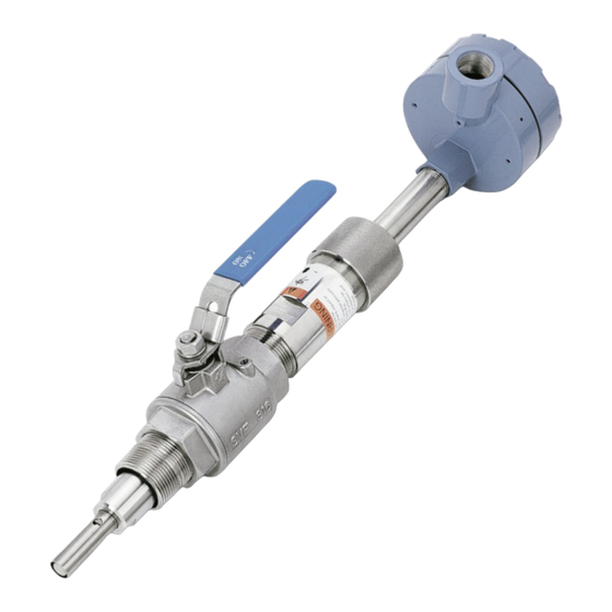
Installation Quick Start Guide May 2019 00825-0100-3402 Installation and Retraction of Sensor Figure 2-3 Label 2.1.1 Installation Retraction assembly kit (PN 23765-00) consists of items 1 through 7 shown in Figure 2-4 as well as a hex key and pipe tape. The sensor assembly includes items 8 through 11. IMPORTANT Do not remove or alter the guard (10) on the sensor tube (9). - Page 11 Quick Start Guide Installation 00825-0100-3402 May 2019 Slide the handle lock up on the ball valve handle and close the ball valve (2). If the process will be restarted before the sensor is installed, make sure the system pressure is at or below 542 kPa abs (64 psig) before proceeding.
- Page 12 Failure to withdraw the sensor completely may result in damage to the electrodes when the valve is closed. Unscrew the packing adapter (3) from the ball valve (2) to remove the sensor and retraction assembly. Figure 2-6 Rosemount 402 Contacting Conductivity Sensor in Retracted Position Installation...
-
Page 13: Section 3: Wiring
Quick Start Guide Wiring 00825-0100-3402 May 2019 Section 3: Wiring Wiring for Rosemount 402/402VP For other wiring diagrams not shown below, please refer to the Liquid Transmitter Wiring Diagrams. Figure 3-1: Wire color and connections in sensor Figure 3-2: Wiring for integral junction box... - Page 14 Wiring Quick Start Guide May 2019 00825-0100-3402 Figure 3-3: Wiring for Rosemount 56 and 1056 transmitters Figure 3-4: Wiring for Rosemount 56 and 1056 transmitters Wiring...
- Page 15 Quick Start Guide Wiring 00825-0100-3402 May 2019 Figure 3-5: Wiring for Rosemount 5081 transmitter 3.1.1 Wiring through a Junction Box If wiring connections are made through a remote junction box (PN 23550-00), wire point-to-point. Use interconnecting cable 23747-00 (factory-terminated) or 9200275 (no terminations). Figure 3-6: Pin out diagram for Rosemount 402VP contacting conductivity sensors with Variopol cable connection Wiring...
- Page 16 Wiring Quick Start Guide May 2019 00825-0100-3402 Wiring...
-
Page 17: Section 4: Calibration And Maintenance
Calibrating the sensor Rosemount 402 conductivity sensors are calibrated at the factory and do not need calibration when first placed in service. Simply enter the cell constant printed on the label into the transmitter. After a period of service, the sensor may require calibration. The sensor can be calibrated against a solution having known conductivity or against a referee meter and sensor. - Page 18 Calibration and Maintenance Quick Start Guide May 2019 00825-0100-3402 Calibration and Maintenance...
-
Page 19: Section 5: Troubleshooting
Quick Start Guide Troubleshooting 00825-0100-3402 May 2019 Section 5: Troubleshooting Troubleshooting Table 5-1: Troubleshooting Trouble Probable Cause Remedy Wiring is incorrect. Verify wiring. Temperature element is open or shorted. Check temperature element for open or short circuits. See Figure 5-1. Off-scale reading Sensor is not in process stream. - Page 20 Troubleshooting Quick Start Guide May 2019 00825-0100-3402 5.1.1 Checking the temperature element Disconnect leads and measure resistance shown. The measured resistance should be close to the value in the table. Figure 5-1 Checking the temperature element Temperature Resistance in ohms (°C) Pt 100 Pt 1000...
-
Page 21: Section 6: Accessories
Quick Start Guide Accessories 00825-0100-3402 May 2019 Section 6: Accessories Accessories Table 6-1: Accessories for Rosemount 402/402VP Contacting Conductivity Sensor accessories information Part Number Description 23550-00 Remote junction box without preamplifier 23747-00 Interconnect cable, prepped (must specify length) 9200275 Extension cable, unprepped (must specify length) - Page 22 Quick Start Guide May 2019 00825-0100-3402...
- Page 23 Quick Start Guide 00825-0100-3402 May 2019...
- Page 24 ©2018 Emerson Automation Solutions. All rights reserved. Emerson Automation Solutions The Emerson logo is a trademark and service mark of Emerson Electric Co. Rosemount is a mark of 8200 Market Blvd. one of the Emerson family of companies. All other marks are the property of their respective Chanhassen, MN 55317, owners.
Need help?
Do you have a question about the Rosemount 402 and is the answer not in the manual?
Questions and answers