
Related Manuals for Emerson Rosemount 499ACL-03


Summary of Contents for Emerson Rosemount 499ACL-03
- Page 1 Quick Start Guide 00825-0300-3499, Rev AB November 2019 ™ Rosemount 499ACL-03 Monochloramine Sensor...
-
Page 2: Table Of Contents
Physical security is an important part of any security program and fundamental to protecting your system. Restrict physical access by unauthorized personnel to protect end users’ assets. This is true for all systems used within the facility. Contents First steps............................. 3 Install............................5 Wire............................. 7 Calibrate............................ 12 Maintenance..........................14 Accessories..........................16 Emerson.com/Rosemount... -
Page 3: First Steps
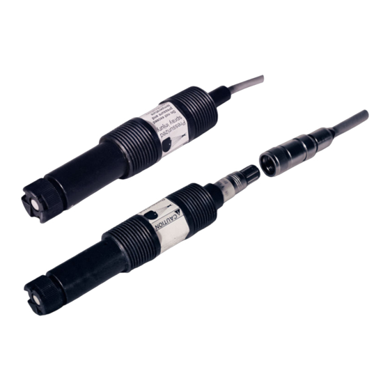
2. If there is no apparent damage, unpack the container. Be sure all items shown on the packing list are present. If items are missing, notify Emerson immediately. Product description Figure 1-1: Rosemount 499ACL-03 Sensor Parts A. Membrane retainer B. Membrane assembly C. O-ring D. - Page 4 316 stainless tubing steel, and silicone Flow cell must drain to open atmosphere. Do not install the sensor in a pressurized line. Temperature and pressure specifications for the low flow cell exceed the temperature and pressure specifications for the sensor. Emerson.com/Rosemount...
-
Page 5: Install
November 2019 Quick Start Guide Install Install sensor in the low flow cell (PN 24091-01) only. Keep the flow as constant as possible between 1 and 4 gph (3.8 to 15 L/hr). The flow cell must drain to open atmosphere. Figure 2-1: Sensor Orientation Install sensor within 45 degrees of vertical. - Page 6 Quick Start Guide November 2019 Figure 2-2: Low Flow Cell (PN 24091-00) A. Inches B. Millimeters C. Outlet D. Inlet Emerson.com/Rosemount...
-
Page 7: Wire
Liquid Transmitter Wiring Diagrams. Figure 3-1: Rosemount 499ACL-03 Sensor Wiring to Rosemount 1056 and 56 Transmitters Table 3-1: Rosemount 499ACL-03 Sensor Wiring to Rosemount 1056 and 56 Transmitters Terminal Letter Wire color... - Page 8 Quick Start Guide November 2019 Table 3-1: Rosemount 499ACL-03 Sensor Wiring to Rosemount 1056 and 56 Transmitters (continued) Terminal Letter Wire color Description number Orange Cathode Figure 3-2: Rosemount 499ACL-03 Sensor Wiring to Rosemount 5081 Transmitter Table 3-2: Rosemount 499ACL-03 Sensor Wiring to Rosemount 5081 Transmitter...
- Page 9 November 2019 Quick Start Guide Table 3-2: Rosemount 499ACL-03 Sensor Wiring to Rosemount 5081 Transmitter (continued) Terminal Letter Wire color Description number White/red RTD sense RTD in Reference guard Reference in Clear Solution ground pH guard pH in -5 V...
- Page 10 Quick Start Guide November 2019 Figure 3-3: Rosemount 499ACL-03 Sensor Wiring to Rosemount 1066 Transmitter Note Connect clear shield wires to solution ground terminal on TB 2. Use wire nut and pigtail if necessary. Table 3-3: Rosemount 499ACL-03 Wiring to Rosemount 1066...
- Page 11 November 2019 Quick Start Guide Figure 3-4: Rosemount 499ACL-03-01-54-VP Sensor Pin-out Diagram (Top View of Connector End of Sensor) Table 3-4: Pin-out Diagram Terminal number Description Cathode RTD sense Anode RTD return RTD in When making a connection through a junction box (PN 23550-00), wire point-to-point.
-
Page 12: Calibrate
4. Adjust the concentration so that it is near the upper end of the operating range. 5. Wait for the readings to stabilize. 6. Follow the transmitter prompts to complete the calibration. Note Refer to the manual for the transmitter you are using (Rosemount 56, 1056, or 1066). Emerson.com/Rosemount... - Page 13 November 2019 Quick Start Guide Be sure taking the sample does not alter flow to the sensor. 7. After calibration, go to the Diagnostics menu and check the sensitivity. The sensitivity should be between 250 and 450 nA/ppm. For more information, refer to the transmitter manual.
-
Page 14: Maintenance
4. Remove the fill plug. 5. Allow the electrolyte solution to drain out. 6. Remove the old pipe tape from the plug. 7. Wrap the plug with one or two turns of pipe tape.. 8. Prepare a new membrane. Emerson.com/Rosemount... - Page 15 November 2019 Quick Start Guide a) Hold the membrane assembly with the cup formed by the membrane and membrane holder pointing up. b) Fill the cup with electrolyte solution. 9. Hold the sensor at about a 45 degree angle with the cathode end pointing up.
-
Page 16: Accessories
9550094 O-ring, Viton 2-014 33521-00 Membrane retainer 23501-09 Monochloramine membrane assembly: includes one membrane assembly and one O-ring 23502-09 Monochloramine membrane kit: includes three membrane assemblies and three O-rings 9210372 Monochloramine sensor fill solution, 4 oz (120 mL) Emerson.com/Rosemount... - Page 17 November 2019 Quick Start Guide Quick Start Guide...
- Page 18 Quick Start Guide November 2019 Emerson.com/Rosemount...
- Page 19 November 2019 Quick Start Guide Quick Start Guide...
- Page 20 Linkedin.com/company/Emerson- Automation-Solutions The Emerson logo is a trademark and service mark of Emerson Electric Co. Rosemount is a twitter.com/rosemount_news mark of one of the Emerson family of companies. Facebook.com/Rosemount All other marks are the property of their youtube.com/RosemountMeasurement respective owners.
Need help?
Do you have a question about the Rosemount 499ACL-03 and is the answer not in the manual?
Questions and answers