
Related Manuals for Emerson Rosemount 499AOZ


Summary of Contents for Emerson Rosemount 499AOZ
- Page 1 Quick Start Guide 00825-0100-3492, Rev AA May 2019 ™ Rosemount 499AOZ Dissolved Ozone Sensor...
-
Page 2: Table Of Contents
Physical security is an important part of any security program and fundamental to protecting your system. Restrict physical access by unauthorized personnel to protect end users’ assets. This is true for all systems used within the facility. Contents First steps............................. 3 Install............................6 Wire............................10 Calibrate............................ 17 Maintenance..........................19 Accessories..........................22 Emerson.com/Rosemount... -
Page 3: First Steps
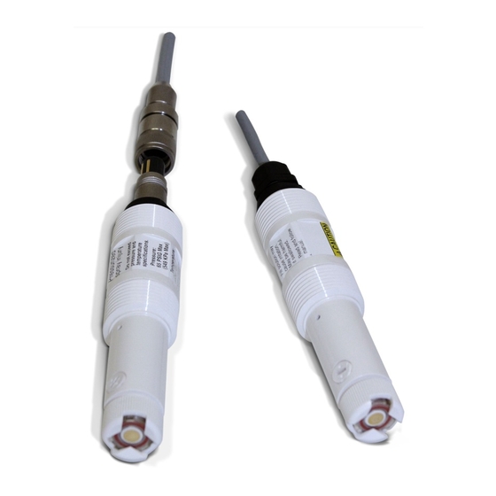
1. Inspect the shipping container. If it is damaged, contact the shipper immediately for instructions. 2. If there is no apparent damage, unpack the container. Be sure all items shown on the packing list are present. If items are missing, notify Emerson immediately. Product description ™ Figure 1-1: Rosemount 499AOZSensor Parts A. - Page 4 80 915240-05 1-1/2 in. NFPT Low flow 24091-00 and Polycarbonat Compression 70 °C (158 °F) 90 psig (722 cell 24091-01 e/polyester, fitting for 1/4 kPa abs) 316 stainless in. O.D. steel, and tubing or 1/4 silicone in. FNPT Emerson.com/Rosemount...
- Page 5 May 2019 Quick Start Guide Table 1-2: Other Specifications (continued) Type Wetted Process Maximum Maximum materials connection temperature pressure Valved 9390004 for Acrylic, 316 1/4 in. NFPT 65 °C (150 °F) 100 psig (858 rotameter use with low stainless (316 stainless kPa abs) flow cell steel, and...
-
Page 6: Install
Sample flow unit Flow limits Flow through 1 to 5 gpm (3.8 to 19 L/min) Open channel 1 ft/sec (0.3 m/sec) Low flow cell 2 to 5 gph (7.6 to 19 L/hr) Figure 2-1: Sensor Orientation Emerson.com/Rosemount... - Page 7 May 2019 Quick Start Guide Figure 2-2: Flow Through 1-1/2 in. Tee A. Union coupler B. 1 in. NPT (2 places) C. Sensor body: Rosemount 499A D. 1 in. NPT flow cell adapter E. O-ring 2-222 F. 1 1/2 in. sched 80 CPVC tee body Quick Start Guide...
- Page 8 Quick Start Guide May 2019 Figure 2-3: Flow Through 2 in. Tee A. Union coupler B. Adapter C. 1 in. NPT (2 places) D. Sensor body: Rosemount 499A E. O-ring 2-222 F. 2 in. sched 80 PVC tee body Emerson.com/Rosemount...
- Page 9 May 2019 Quick Start Guide Figure 2-4: Low Flow Cell (PN 24091-00) Quick Start Guide...
-
Page 10: Wire
Quick Start Guide May 2019 Wire NOTICE For additional wiring information on this product, including sensor combinations not shown here, please refer to the Liquid Transmitter Wiring Diagrams. ™ Figure 3-1: Rosemount 499AOZ-54 Sensor Wiring to Rosemount 1056 and 56 Transmitters Emerson.com/Rosemount... - Page 11 May 2019 Quick Start Guide Figure 3-2: Rosemount 499AOZ-54-60 and Rosemount 499AOZ-54-VP Sensor Wiring to Rosemount 1056 and 56 Transmitters Quick Start Guide...
- Page 12 Quick Start Guide May 2019 Figure 3-3: Rosemount 499AOZ-54 Sensor Wiring to Rosemount 5081 Transmitter Emerson.com/Rosemount...
- Page 13 May 2019 Quick Start Guide Figure 3-4: Rosemount 499AOZ-60 and 499AOZ-VP Sensor Wiring to Rosemount 5081 Transmitter Quick Start Guide...
- Page 14 Quick Start Guide May 2019 Figure 3-5: Rosemount 499AOZ-54 Sensor Wiring to Rosemount 1066 Transmitter Note Connect clear shield wires to sol gnd terminal on TB 2. Use wire nut and pigtail if necessary. Emerson.com/Rosemount...
- Page 15 May 2019 Quick Start Guide Figure 3-6: Rosemount 499AOZ-60 and 499AOZ-54-VP Sensor Wiring to Rosemount 1066 Transmitter Note Connect clear shield wires to solution ground terminal on TB 2. Use wire nut and pigtail if necessary. Figure 3-7: Rosemount 499AOZ Sensor Pin-out Diagram...
- Page 16 Quick Start Guide May 2019 When making a connection through a junction box (PN 23550-00), wire point-to-point. NOTICE Use a wire nut and pigtail (included) when connecting several wires to the same terminal. Emerson.com/Rosemount...
-
Page 17: Calibrate
Calibrate Zero point calibration Even in the absence of ozone, the Rosemount 499AOZ sensor generates a small signal called the zero current. Failing to correct for the zero current can introduce a bias, particularly if the ozone concentration is small (<0.4 ppm). - Page 18 Quick Start Guide May 2019 7. After calibration, go to the Diagnostics menu and check the sensitivity. The sensitivity should be between 250 and 450 nA/ppm. For more information, refer to the transmitter manual. Emerson.com/Rosemount...
-
Page 19: Maintenance
May 2019 Quick Start Guide Maintenance Periodic maintenance and cleaning are required for best performance of the sensor. Generally, the membrane and fill solution should be replaced every four to six months. Sensors installed in harsh or dirty environments require more frequent maintenance. - Page 20 Be sure the holes remain covered with electrolyte solution. 20. Place a drop of electrolyte solution on the cathode; then place the membrane assembly over the cathode. 21. Screw the membrane retainer in place. Emerson.com/Rosemount...
- Page 21 May 2019 Quick Start Guide The sensor may require several hours operating at the polarizing voltage to equilibrate after the electrolyte solution has been replenished. Quick Start Guide...
-
Page 22: Accessories
Dissolved ozone membrane assembly; includes 1 membrane assembly and 1 O-ring 23502-11 Dissolved ozone membrane assembly; includes 3 membrane assemblies and 3 O-rings 9210299 #3 Dissolved ozone sensor fill solution, 4 oz (125 ml) 33521-02 Membrane retainer 33523-03 Fill plug Emerson.com/Rosemount... - Page 23 May 2019 Quick Start Guide Quick Start Guide...
- Page 24 Linkedin.com/company/Emerson- Automation-Solutions The Emerson logo is a trademark and service mark of Emerson Electric Co. Rosemount is a twitter.com/rosemount_news mark of one of the Emerson family of companies. Facebook.com/Rosemount All other marks are the property of their youtube.com/RosemountMeasurement respective owners.
Need help?
Do you have a question about the Rosemount 499AOZ and is the answer not in the manual?
Questions and answers