ZyXEL Communications Omni TA128 User Manual
Hide thumbs
Also See for Omni TA128:
- User manual (169 pages) ,
- Quick start manual (33 pages) ,
- Brochure & specs (2 pages)
Table of Contents
Advertisement
Quick Links
Advertisement
Table of Contents

Subscribe to Our Youtube Channel
Related Manuals for ZyXEL Communications Omni TA128


Summary of Contents for ZyXEL Communications Omni TA128
- Page 1 Omni TA128 User’s Manual...
-
Page 2: Foreword
The contents of this book may not be reproduced (in any part or as a whole) or transmitted in any form or by any means without the written permission of the publisher. Published by ZyXEL Communications, Inc. All rights reserved. Notice: ZyXEL does not assume any liability arising out of the application or use of any products, or software described herein. -
Page 3: Fcc Part 15 Information
Shielded RS-232 cables are required to be use d to ensure compliance with FCC Part 15, and it is the responsibility of the user to provide and use shielded RS-232 cables. Omni TA128; FCC ID# i88OMNITA128U... -
Page 4: Information For Canadian Users
Foreword Information for Canadian Users The Industry Canada (IC, formerly DOC) label identifies certified equipment. This certification means that the equipment meets certain telecommunications network protective, operational, and safety requirements. IC does not guarantee that the equipment will operate to a user’s satisfaction. Before installing this equipment, users should ensure that it is permissible to be connected to the facilities of the local telecommunications company. -
Page 5: Table Of Contents
Chapter 2 - Installing your Omni TA128......2-1 Connecting Your Omni TA128 to the Power Supply..........2-1 Connecting the Omni TA128 to Your Computer...........2-2 Connecting the Omni TA128 to Your ISDN Line ..........2-3 S/T Interface Model ..................2-3 U Interface Model ..................2-4 Power On and Self Diagnostics ................2-4 Omni TA128 Front Panel ...................2-5... - Page 6 Table of Contents Chapter 4 - ISDN Communication Basics .....4-1 Outgoing Calls ....................4-1 Dialing out using ISDN mode ................4-1 Dialing out using ISDN mode optional Speech Bearer Service ......4-1 Dialing out for Analog Adapter Port 1............4-2 Manually switching communication modes .............4-2 Placing the Call ....................4-2 Incoming Calls....................4-2 Answering a Call using MSN .................4-5...
- Page 7 Table of Contents Answering an X.75 call..................8-1 Making an X.75 Call ..................8-2 Making a Bundled Call with X.75..............8-2 Dynamic Bandwidth Allocation ..............8-3 Invoking V.42bis Data Compression ..............8-4 Data Encryption....................8-5 Manual DES Key Generation .................8-6 Control of Data Encryption................8-8 Chapter 9 - V.110 ISDN Communications......9-1 Answering a V.110 call..................9-1 Making V.110 Calls....................9-2 Asynchronous V.110 Calls................9-2...
- Page 8 Table of Contents Non-password Auto Call Back Function............. 12-3 Chapter 13 - Upgrading Your Omni TA128....13-1 Upgrading with Flash EPROM................13-1 Chapter 14 - Usage of DTE Port 2........14-1 Selection of the Two DTE Port Mode ............... 14-1 Configuration of the DTE Port 2 ............... 14-2 Basic "AT"...
- Page 9 Table of Contents Terminal Adapter..................... 18-1 Basic Rate Interface (BRI)................18-1 D channel Protocol..................18-1 Rate Adaptation & B channel Protocol ............18-2 Out-of-band signaling.................. 18-2 ISDN Basic Rate Interface Points ..............18-3 Chapter 19 - Ordering Your ISDN Line ......19-1 ISDN Service Ordering Information .............
-
Page 10: Chapter 1 - Introduction
EPROMs, which allow for convenient uploading of newly available firmware which preserves your hardware investment. The Omni TA128 supports both D and B Channels protocols. For the D Channel, it supports DSS1, 1TR6, DMS-100, AT&T Custom, and NI-1. For the B Channels, X.75 SLP, V.120, V.110, PPP Async-to-sync Conversion and Bundle (128Kbps). -
Page 11: U-Interface Option
- Asynchronous: Data Rate up to 230.4Kbps - Synchronous mode Note: At the time of its initial release on the market, the Omni TA128’s Synchronous DTE mode is not available. This feature will be firmware upgradeable at a later time (date to be confirmed). -
Page 12: Unpacking Your Omni Ta128
Chapter 1 - Introduction Unpacking Your Omni TA128 Your Omni TA128 modem should come with the equipment listed below. If any item is missing or damaged, please contact your Dealer or ZyXEL Customer Service Department immediately. one (1) Omni TA128 ISDN Terminal Adapter... -
Page 13: Chapter 2 - Installing Your Omni Ta128
Plug the power supply unit to an AC wall jack then turn on the power switch on the Omni TA128. Observe the LED light status on the front panel of your Omni TA128 and make sure PWR LED is on. -
Page 14: Connecting The Omni Ta128 To Your Computer
(the one with 25 pin connector) should be used Your Omni TA128 comes with a 25 pin, male to female cable, which is to be used to connect the main serial port of Omni TA128 to your computer serial port. Please see... -
Page 15: Connecting The Omni Ta128 To Your Isdn Line
Omni TA128U comes with a U interface. This allows you to connect directly to your ISDN wall jack. S/T Interface Model If you have purchased the Omni TA128 or Omni TA128S/T model, you will need an NT-1 device to connect to the network. Figure 2-3... -
Page 16: U Interface Model
Chapter 2 - Installing your Omni TA128 The cable connecting the NT-1 device to the Omni TA128 is provided for you. It is an RJ-45 to RJ-45 cable with four conductors running through it. Once everything is set up, connect the Omni TA128 to your ISDN line: Use the phone cable (RJ-45) that is included, connect the Omni TA128 “ISDN S”... -
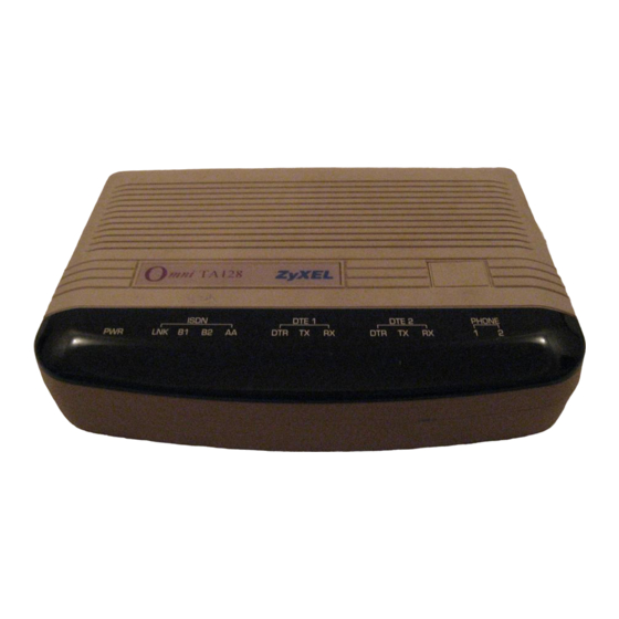
Page 17: Omni Ta128 Front Panel
Figure 2-4 The LED Indicators P o w e r on indicator; lights up when the Omni TA128's power is turned ON. Physical layer (layer 1) active indicator; lights up when Layer 1 of the S0 interface is active; flashes when the data link layer of D channel is in multiple frame mode. -
Page 18: Front Panel Switch
Command statements must be written in a specific form in order for the Omni TA128 to recognize them. A command statement begins with the letters “AT” or “at”. It is then followed by one or more commands and then by a<Enter>. -
Page 19: Supported At Command Types
ATB0 since both B1 and B0 can not co-exist. If you see duplicated characters for each one you type, your Omni TA128 and software both have their echo feature turned on (the Omni TA128 defaults to enable command echo). -
Page 20: Chapter 3 - Configuring Your Isdn Line And Network
ZyXEL ISDN Configuration Manager. Figure 3-1 ISDN Configuration Manager If your Omni TA128 is not going to be set-up by a computer running Windows, you will need some type of terminal program that allows you to send AT commands to the... -
Page 21: Configuring Your Modem Using A Terminal Program
Configuring your Modem using a Terminal program Getting a Terminal Program Ready If you are not using the ISDN configuration utility that is packaged with the Omni TA128, you will need a terminal program to from which to configure the unit. The Omni should work with any asynchronous terminal program that can communicate directly with one of the communication ports on your system. -
Page 22: Configuring Your Isdn Line Switch Type And Spid
The ATPn command is used to program the D channel protocol. This is to allow the Omni TA128 to work with the type of switch your ISDN line is connected to. “n” is a digit that indicates the type of switch. Please use the following table for the “n” value. -
Page 23: Spid Setup
SPID Error! This indicates an error entering the SPID number. Once the SPID(s) are entered and accepted, toggle the Omni TA128 power off then back on. Wait until you see the LNK LED light up (this indicates an open communication link between your TA and the local switch). -
Page 24: Testing Your Connection
TA128 to connect and then communicate over the line. Making Your First ISDN Data Connection Your Omni TA128 should already be connected to you ISDN line properly. Also make sure that the LNK LED light is on. If the LED is unlit, check that your ISDN switch setup and SPID number(s) are correct. - Page 25 To make a bundled connection, follow the above instructions, with one change. You must let the Omni TA128 know that you want to make a bundled connection. Typing AT&J3 will tell the Omni TA128 to set up a bundled call.
- Page 26 Chapter 3 - Configuring Your ISDN Line and Network FrontDoor 2.20c.mL/OX000046; MultiLine Press <Esc> twice for ZyXEL BBS From this screen, you can either continue or hang up.
-
Page 27: Chapter 4 - Isdn Communication Basics
At your terminal program, proceed with the following instructions: Dialing out using ISDN mode The command “ATDI” tells your Omni TA128 that you want to make an ISDN data call and to therefore use the ISDN mode to call out. Type: ATDI17142630398<enter>... -
Page 28: Manually Switching Communication Modes
Be aware that the Omni TA128 will not automatically answer a call unless S- register S0 is set to a value greater than 0 (zero). If S-register S0=0, the Omni TA128 will only report “RING” to your terminal program. It can also respond with an audible tone... - Page 29 Chapter 4 - ISDN Communication Basics When an ISDN data call comes in, the Omni TA128 will try to negotiate a connection using the proper ISDN protocol. When an analog call comes in, the Omni TA128 will send the call to the analog port as the factory default, Phone 1 and then Phone 2.
-
Page 30: Answering A Call Using Msn
Called_Party_Subaddress information within the incoming SETUP message is not used by the Omni TA128 to select the protocols or services. It just indicates the subaddress (if any) to the DTE. Data over Speech Channel If you are expecting ISDN data calls through Speech (Voice) channel, you would need to setup MSN for it. -
Page 31: Best-Effort Call Answering
Phone 1. Multi auto-answering of data calls When an ISDN data call comes in, the Omni TA128 can determine the protocol to be used in one of two exclusive ways. By way of the information conveyed by the SETUP message (for DSS1, these include the Bearer-Capability, Low-Layer-Compatibility, or High-Layer- Compatibility information elements;... - Page 32 TA128 will go into its “Multi Auto-answering Routine,” by examining the B channel data pattern and hence determine the protocol to use. When alerted, the Omni TA128 will send a RING message to the DTE in the following format: RING...
-
Page 33: Chapter 5 - Setup For Windows 95 And Nt
Chapter 5 - Setup for Windows 95 and NT This chapter contains step by step procedures for installing the Windows 95 and NT drivers, and configuring Dial-up Networking for the Omni TA128. Installing the Windows 95 Driver (INF file) Step 1 - Open the Control Panel by double clicking the “Control Panel” icon in your “My Computer”... - Page 34 “Browse” to find the location of the updated .INF file, click “Open,” then click “OK.” Step 6 - Select the Omni TA128 driver with the protocol that your host is using. Generally, the samples listed below will work. However, we recommend that you check with your ISP to verify the protocol they use.
-
Page 35: Configuring Windows 95 Dial-Up Networking
Click “Finish.” You should see a window similar to the one below. Step 8 - Click “Close.” This completes the installation of your Omni TA128 modem driver. You may now use programs such as “Dial-Up Networking” with your Omni TA128. - Page 36 Chapter 5 - Setup for Windows 95 and NT Step 2 - Choose a name for your connection and select your modem type from the drop down window. Then click on the “Next” button. Step 3 - Type the phone number of your ISP or whatever host you will be calling. Click on the “Next”...
- Page 37 Chapter 5 - Setup for Windows 95 and NT Step 5 - Make sure your Omni TA128 modem appears in the “Connect Using” box. Then click on the “Server Type” button. These options are mostly host or server specific. If you are using PPP, use the default settings shown above.
- Page 38 “Dial-up Networking” folder, and double click on it. Step 8 - If the User name and Password are incorrect or are not there, type them in. Click on the Connect button and your Omni TA128 will dial the number and establish a connection.
-
Page 39: Windows Nt Ras Setup
Chapter 5 - Setup for Windows 95 and NT Windows NT RAS Setup From the NT Program Manager open the “Main” program group and double click on “Control Panel,” then double click on Network. This will bring up Network Settings. If you have not already done so, create a Computer name and Workgroup name for your system. - Page 40 “Security” button. The rest of this is dependent on your ISP. If you are making an NT to NT server just check “Accept Authentication,” and click OK. 18) Finally Click OK again, then click “Dial.” Your Omni TA128 will dial the number and establish a connection.
-
Page 41: Chapter 6 - Async To Sync Ppp And Slip
Making Async to Sync PPP and SLIP calls In order to communicate with an ISDN LAN router (from vendors such as Ascend and Cisco), you’ll need to set the Omni TA128 B channel protocol to one of the following: ATB40<Enter> (HDLC PPP) ATB41<Enter>(HDLC SLIP) -
Page 42: Keeping A Line Connection During Idle Time
The value in register S124 (in seconds) is used as the idle time gauge. If the idle time exceeds this guarding period, the Omni TA128 will send out a dummy PPP packet to the Server to keep it from disconnecting the line. -
Page 43: Endpoint Discriminator
Chapter 6 - Async to Sync PPP and SLIP By default, the Omni TA128 dials the same number for both Multilink PPP connections. If the destination you are dialing requires two different telephone numbers to establish a two channel Multilink PPP connection, then the following command can be used: ATDIphone_number_1+phone_number_2 where phone_number_1 and phone_number_2 are the phone numbers of the destination. -
Page 44: Dynamic Bandwidth Allocation
Omni TA128 automatically reestablishes that channel for Multilink PPP operation. The dynamic bandwidth allocation function can only be effective when the Omni TA128 is in the calling site (the client site). The following command can be used to select the DBA function:... -
Page 45: Chapter 7 - V.120 Isdn Communications
TA128 to 56K mode using the AT&E1 command (AT&E0 to set it back to 64k mode.) If your Omni TA128 is on the receiving end, you can keep the setting at AT&E0, 64k data mode. The Omni TA128 will automatically switch between the two speeds in answer mode. -
Page 46: Answering Incoming Calls
In most cases, there is no need to configure the Omni TA128 to properly answer calls. The Omni TA128 is able to decide which protocol to use by detecting the type of data that is coming in. All you need to do is set S0 to greater than or equal to 1, so the Omni TA128 will automatically answer an incoming call. -
Page 47: Making A Bundled Call With V.120
“ATD” command: ATDI[phone_number_1]+[phone_number_2]<Enter> The answering Omni TA128 determines that the call is a bundle request: when AT&J3 is set, and two consecutive SETUP messages are received. The two data calls are established as one message. The phone company’s ISDN line splits it off into two messages. -
Page 48: Dynamic Bandwidth Allocation
(and only one) from a device that is attached to one of the a/b adapters while a CCB call is active. The Omni TA128 automatically removes one of the CCB connections and uses it for the voice call. Once the voice call ends, the Omni TA128 automatically reestablishes that channel for CCB operation. - Page 49 Chapter 7 - V.120 ISDN Communications It takes extra time for the calling ISDN TA to negotiate V.42bis. If you know in advance that the called site has no V.42bis capability, it would be better to issue the AT&K00 command beforehand in order to get a quick connection. V.42bis is an international data compression standard commonly used in modem communications.
-
Page 50: Selecting V.120 For European Isdn (Dss1) Switch
If the called TA doesn't get any B channel protocol information from the incoming SETUP message and the remote device is a ZyXEL ISDN device, the Omni TA128 will be able to identify the V.120 protocol automatically with the Multi Auto-answer routine. -
Page 51: Chapter 8 - X.75 Isdn Communications
AT&ZI0=n. Please refer to the section entitled “Data over Speech Channel” in Chapter 4 for details. To allow the Omni TA128 to answer the incoming call, you need to set S0 to a value greater than 0 (i.e. ATS0=1). The Omni TA128 will answer the call and use asynchronous to synchronous conversions to and from the DTE. -
Page 52: Making An X.75 Call
CAPI 1.1a specifies X.75 with T.70 NL as its default. CAPI 2.0 specifies X.75 with transparent layer 3 as its default. The default data protocol of the Omni TA128 is ATB20 (V.120). X.75 protocols can be chosen using the following AT commands: ATB00 X.75 with transparent layer 3... -
Page 53: Dynamic Bandwidth Allocation
(and only one) from a device that is attached to one of the a/b adapters while a CCB call is active. The Omni TA128 automatically removes one of the CCB connections and uses it for the voice call. Once the voice call ends, the Omni TA128 automatically reestablishes that channel for CCB operation. -
Page 54: Invoking V.42Bis Data Compression
Chapter 8 - X.75 ISDN Communications Bundle Type S100=0 S100=1 Selection V.42bis Yes (AT&K44) Yes (AT&K44) In-band Bundle Negotiation End Point Optional Discrimination Invoking V.42bis Data Compression The following AT commands are used to switch the V.42bis data compression on or off for ISDN data calls when using X.75 or V.120 protocols. -
Page 55: Data Encryption
But the weak keys will be automatically avoided by Omni TA128. One major criticism of the DES standard is that its key is too short to survive the brute force (exhaustive search) attack of today’s technology. -
Page 56: Manual Des Key Generation
65. The AT command interpreter will convert the string DES_Key to a real DES key. The Omni TA128 will check to see if the converted key is a weak key for DES, if so, it modifies the key according to a predetermined algorithm to get a non-weak key. -
Page 57: Control Of Data Encryption
Chapter 8 - X.75 ISDN Communications Control of Data Encryption The AT commands to control the data encryption are as follows : S Register setting Description ATS89.0 = 1 DES is desired ATS89.0 = 0 DES is disabled (Default) ATS89.1 = 1 Triple DES is preferred ATS89.1 = 0 Single DES is preferred (Default) -
Page 58: Chapter 9 - V.110 Isdn Communications
AT&ZI1=n. Please refer to the section entitled “Data over Speech Channel” in Chapter 4 for details. To allow the Omni TA128 to answer the incoming call, you need to set S0 to a value greater than 0 (i.e. ATS0=1). Omni TA128 will answer the call and use asynchronous to... -
Page 59: Making V.110 Calls
Making V.110 Calls Asynchronous V.110 Calls Before ATDIxxx command is issue to make the dialing, you need to make sure that the Omni TA128 is in the asynchronous mode (AT&M0). Then use the following commands to configure V.110: AT Command... - Page 60 User rate = 56000bps ATB11 User rate = 64000bps Table 9-3 Note : The Omni TA128 does not support network independent clock compensation. The synchronous timing source must be supplied by the Omni TA128, which is phase locked to the network synchronous clock.
-
Page 61: Chapter 10 - Handling Analog Calls
DTMF tone/pulse dialing can be plugged into any one of the two RJ-11 sockets (labeled phone 1 and phone 2) of the Omni TA128. This chapter will outline the steps you need to take to place and answer analog calls via your ISDN line. -
Page 62: Placing A Call From The Analog Adapter
Use ATDAs (ATDBs) to place a call for the analog adapter 1 (analog adapter 2) The way the analog ports work for Omni TA128 is: once the analog adapter's hook sensor detects that the telephone device’s handset is picked up (off hook), it sends a SETUP message to the ISDN central exchange to request a connection. -
Page 63: Chapter 11 - Advanced Isdn Call Control
Chapter 11 - Advanced ISDN Call Control Chapter 11 - Advanced ISDN Call Control Call Control for DSS1 (Digital Subscriber Signaling #1) In order to initiate an DSS1 ISDN call, two information elements are necessary: The Bearer Capability element indicates what kind of bearer service is desired. It is also used for compatibility checking in the addressed entity. -
Page 64: Control Of Isdn Phone Number And Sub-Address
Chapter 11 - Advanced ISDN Call Control Bearer-Capability and Low-Layer-Compatibility information elements will be determined when you configure the B channel protocols using the command ATBnn. The outgoing Low-Layer-Compatibility information element can be turned on or off by setting S80 bit ‘n’ as follows: n = 4 for the analog adapter 2 n = 6 for ISDN data calls n = 7 for the analog adapter 1... -
Page 65: Call Control For 1Tr6 (Old German Isdn)
The default settings of the Phone Number and Subaddress of all the types of calls are UNASSIGNED - meaning the SETUP message sent by the Omni TA128 contains neither Calling-Party-Number nor Calling-Party-Subaddress information elements. The command AT&ZO? can be used to browse the current settings of the own numbers and subaddresses. -
Page 66: Control Of Endgeräteauswahlziffer (Eaz)
If this suffix digit is omitted, the switch will assume the EAZ as 0. Each type of outgoing call of the Omni TA128 can be assigned with one origination EAZ by using the command AT&ZO x =Origination_EAZ , (where x = I for ISDN data calls, A for the analog adapter 1, and B for the analog adapter 2). -
Page 67: Answering A Call
(e.g. the calling user) and the addressed entity, can be used for the same purpose as the MSN. Since the Omni TA128 is highly integrated and multi-functional, it can be imagined as a “black box” that contains multiple distinct terminals. Each of these "internal terminals"... -
Page 68: Best-Effort Call Answering
TA128 will, by default, ignore the call as it may be intended for other devices that share the same S/T interface (S0 bus) with the Omni TA128. If you want the Omni TA128 to answer inbound calls as often as possible, you can set the best-effort call answering bit as follows: Answer call only when number matched (by default) S119.3=0... -
Page 69: Disable Inbound Call Connection
Chapter 11 - Advanced ISDN Call Control Data Call Indication Data calls are accepted the same way as in any modem. When alerting, the Omni TA128 will send the first RING message to the DTE with a format as follows: RING <CR><LF>... -
Page 70: Placing A Call
Chapter 11 - Advanced ISDN Call Control Placing a Call To initiate a call, configure the Omni TA128 according to the Bearer Service (or protocol) you want to use. ATBnn for ISDN data call Placing a call for DSS1 The ATDx command is used for dialing as follows. -
Page 71: User-To-User Information
Omni TA128. User-To-User Information Omni TA128 supports user-to-user information exchange via the D channel. To transmit a message, use ATT4<message..> command. The angle brackets '<' and '>' are part of the this command. The message will be included in an User-To-User Information Element which is sent with the first valid MESSAGE that follows. -
Page 72: Chapter 12 - Security Functions
Omni TA128’s pre-stored password list. With a Type 2 connection, the remote terminal will be prompted to enter the password at the initial connection and the local Omni TA128 will match the entered password with the pre- stored password list. -
Page 73: Setting And Modifying Passwords
Supervisory password is required for adding or to modify the entries. The default supervisor password is ZyXEL when Omni TA128 is shipped from the factory. This supervisory password is send to remote if Type 1 security is set at remote end. -
Page 74: Non-Password Auto Call Back Function
Non-password Auto Call Back Function In addition to the standard modem-like security functions described in the previous section, the Omni TA128 provides another simpler call back function. The Calling Party Number (origination address) will be checked against the 5 pre-stored call-back numbers before the B channel is connected. -
Page 75: Chapter 13 - Upgrading Your Omni Ta128
This chapter describes how to upgrade flash EPROM firmware when it is available. Upgrading with Flash EPROM Your Omni TA128 modem employs a flash EEPROM that lets you conveniently download updated firmware and program the modem with new features and enhanced functions. - Page 76 In the unlikely event that your modem fails to respond to AT commands after upgrading the EEPROM follow the procedure below. Power cycle the Omni TA128. The Cold reset will prompt the TA to check the integrity of the codes in the flash EEPROM.
-
Page 77: Chapter 14 - Usage Of Dte Port 2
Chapter 14 - Usage of DTE Port 2 Chapter 14 - Usage of DTE Port 2 This chapter describes how to set the TA128 into Two-DTE Port and One Analog Port mode in which two users can use the TA128 simultaneously to place two independent calls to access the Internet. -
Page 78: Basic "At" Command Set
<any key> Terminate current connection attempt when entered in handshaking state. Escape sequence code, entered in data state, wait for the Omni TA128 to return to command state. All the Following Commands Require an “AT” Prefix Go on-line in answer mode. - Page 79 1282 (DSS1) 1283 (1TR6) Display product information and ROM checksum Results: Omni TA128 <switch>: V x.xx where <switch>= USA, DSS1, or 1TR6 Display Microsoft PnP code Return to on-line state S0=n Set S-register s0. 'n' must be a decimal number...
-
Page 80: Extended "At&" Command Set
Chapter 14 - Usage of DTE Port 2 n=0-7 Result code options, see the Options Table in S131.3-5 Chapter 16 “AT Command Set Reference” Extended "AT&" Command Set Command Options Function & Description Ref. &Cn Carrier Detect (CD) options &C1 * CD tracks presence of carrier All other values are invalid &Dn... -
Page 81: Setting Of Dte Port 2 Speed
Chapter 14 - Usage of DTE Port 2 &ZOn=x Write own phone number (including subaddress, if any). The number specified will be used as the calling party number while dialing. Value for “n” I = ISDN data A= analog adapter, Phone 1 B= analog adapter, Phone 2 Setting of DTE port 2 Speed The DTE speed of DTE port 2 can be configured ONLY through DTE port 1. -
Page 82: Chapter 15 - Diagnostics And Protocol Analyzer
Chapter 15 - Diagnostics and Protocol Analyzer Chapter 15 - Diagnostics and Protocol Analyzer This chapter provides quick easy-reference diagnostic tables for the Omni TA128. The Omni TA128 can perform its own diagnostic tests, which can provide invaluable information about each of its functions. -
Page 83: Loopback With Self-Test (At&T10)
Omni TA128. Some of the tests are interactive operations, just follow the indications prompted on the screen to carry out the tests. If the Omni TA128 is in the normal condition, the test results will be as follows: System address &... -
Page 84: Using The Embedded Protocol Analyzer
The EPA enables you to examine messages exchanged between your Omni TA128 and the Central Exchange office when making an ISDN call. You can review the packets sent or received through the B channel (for X.75 or V.120) to or from the remote site. -
Page 85: Analyzing The Captured Data
Chapter 15 - Diagnostics and Protocol Analyzer The following commands determine the kind of protocol data to be captured by the EPA: AT Command Description ATCDn Disable the capture of D channel protocols Enable the capture of D channel protocols (default) ATCBn Disable the capture of B channel protocols (default) Enable the capture of B channel protocols... -
Page 86: Chapter 16 - At Command Set Reference
Multiplex mode is used as an internal interface for ZyXEL CAPI drivers. Simplex mode In simplex mode, the Omni TA128 is used just like an ordinary modem. The DTE interface will be either in the command state or in the data state. At most, only one data connection session is possible at any time. -
Page 87: Basic "At" Command Set
The following tables list all of the AT commands supported by the Omni TA128. An asterisk * following a command option or value indicates that it is a default setting when the modem is shipped. - Page 88 Chapter 16 - AT Command Set Reference Command Options Function & Description Ref. SLIP async to sync conversion Configuration of embedded protocol analyzer S84.1 Disable the capture of B channel protocols Enable the capture of B channel protocols Configuration of embedded protocol analyzer S84.0 Disable the capture of DTE-DCE interface protocols...
- Page 89 Chapter 16 - AT Command Set Reference Command Options Function & Description Ref. Wait for second dial tone. Remaining digits will be dialed as in-band DTMF. <ISDN numbering options> Unknown type of number International number National number Network specific number Subscriber number Abbreviated number Type of sub-address, NSAP with AFI=$50, IA5...
- Page 90 (USA) 1282 (DSS1) 1283 (1TR6) Display product information and ROM checksum Results: Omni TA128 <switch>: V x.xx where <switch>= USA, DSS1, or 1TR6 Display link status report Display Microsoft PnP code n=0-3 Speaker volume control. The higher the value, S24.4-5...
- Page 91 Chapter 16 - AT Command Set Reference Command Options Function & Description Ref. Tn<string> The <string> will be sent to the called party via a user-to-user information element in the next message. Characters other than the alpha- numeric values can be represented by <nnn> in the string, where nnn is the unsigned value of the character.
-
Page 92: Extended "At&" Command Set
Chapter 16 - AT Command Set Reference Description of ATI3 Output: The Link Status Report output appears as follows: ZyXEL ISDN MODEM LINK STATUS REPORT Connect DTE Speed Error Control Level Protocol Link Speed Bytes Received Bytes Sent Cause Cause Value HDLC FCS Error HDLC Receive Over-run HDLC Transmit Under-run: 0... - Page 93 Chapter 16 - AT Command Set Reference Command Options Function & Description Ref. &Hn Data flow control, DTE/DCE. S27.3-5 &H0 Flow control disabled. &H3 * Hardware (CTS/RTS) flow control &H4 Software (XON/XOFF) flow control. &Jn Bundle selection (See also S100) S87.5-6 &J0 * Bundle connection is disabled...
- Page 94 Chapter 16 - AT Command Set Reference Command Options Function & Description Ref. &Zn=s n=0-39 Write phone number/s to NVRAM at location n (n=0-39) use AT*Dn or ATS29=n to set the default dial pointer. &ZIn=s n=0-7 MSN setting. Assign the phone number s=phone (including subaddress, if any) for various B number...
-
Page 95: Extended "At*" Command Set
Chapter 16 - AT Command Set Reference Extended "AT*" Command Set Command Function & Description Ref. n=0-7 DTE speed for second DTE port S43.0-2 230400 115200 76800 57600 38400 19200 9600 2400 n=0-3 Character length, including start, stop and S15.3-4 parity bit. -
Page 96: Chapter 17 - Status Registers And Result Codes
At the time this manual was written, Omni TA128 was equipped with 124 S-registers, from S0 to S124. S0 to S11 are standard AT S-registers, and S12 to S124 are mostly bit- map configured. - Page 97 Chapter 17 - Status Registers and Result Codes Setting S-registers In order to change the value in S-register ‘r’ to value ‘n’ use: ATSr=n (range 0-255) In order to change the value in a specific bit (b) of S-register r, use: ATSr.b=n (range 0-1) In both commands, n is a decimal number in the given range.
-
Page 98: S-Register Descriptions
Chapter 17 - Status Registers and Result Codes S-Register Descriptions The descriptions for each S-register. In most bit-mapped S-registers, the default bit value is 0 (which is the normal situation) and only the non-default situation is described. Some reserved bits are for factory use and the user should not change them. Values followed by an asterisk * are the factory default settings. - Page 99 Chapter 17 - Status Registers and Result Codes Command Function and description Ref. S18= Force modem or TA to fix baud rate when +000 idle Disable fixed baud function Enable baud rate fixing at idle, n=0-15 baud rate value settings (n) the same as S20 value S20= DTE speed (bps).
- Page 100 Chapter 17 - Status Registers and Result Codes Command Function and description Ref. Display result code in numeric format (see S35.7) Display result code in verbose format S24= Bit mapped register Ring volume control, increments of 1 in N0-3 decimal Ignore S21.1-2 when Phone 1 key pad dialed Do not ignore S21-2 when Phone 1 key...
- Page 101 Chapter 17 - Status Registers and Result Codes Command Function and description Ref. Enable CCITT signals 140 and 141 on EIA-232D interface S42= Bit mapped register +000 Disable escape sequence code in answer mode Disable Data/Voice button Disable <RINGING> result code S43= Second DTE port speed setting +003...
- Page 102 Chapter 17 - Status Registers and Result Codes Command Function and description Ref. V.120 56000 X.75 64000 Transparent X.75 56000 Transparent X.75 64000 T.70 X.75 56000 T.70 X.75 64000 BTX X.75 56000 BTX V.110 64000 V.110 56000 PPP async to sync 64K PPP async to sync 56K SLIP to sync HDLC conversion 64K SLIP to sync HDLC conversion 56K...
- Page 103 Chapter 17 - Status Registers and Result Codes Command Function and description Ref. AT&T proprietary point-to-point AT&T proprietary point-to-multi-point (1 SPID mode) AT&T custom point-to-multipoint (2 SPID mode) S87= Bundle connection is disabled &Jn Bundle connection is enabled in answer mode only Bundle connection is enabled in call mode only...
- Page 104 Chapter 17 - Status Registers and Result Codes Command Function and description Ref. SI=2 2 Fax Gruppe 3 Daten Ober Modem Btx Ober Modem SI=7 0 Daten bertragung 64 Kbps (X.75 SLP) 11------ Async. V.110 01------ Extensions of async. --0----- * Number of data bits: 8 --1----- Number of data bits: 7 ---0---- * Number of stop bits: 1...
- Page 105 Chapter 17 - Status Registers and Result Codes Command Function and description Ref. S117= V.110 user rate S118= Enable dial-in call Disable dial-in call (dial out only) Default B channel line speed is 64Kbps for &E0 ISDN data call Default B channel line speed is 56Kbps for &E1 ISDN data call Use 3.1KHz Bearer service whenever...
-
Page 106: Atxn" Result Code Option Table
Factory default when listed in 'Reference' column. "ATXn" Result Code Option Table The following table shows the different options available when setting the ATXn command. The default value for ‘n’ is 5 when the Omni TA128 is shipped. ATV0 ATV1... -
Page 107: Result Code Field Descriptions
Chapter 17 - Status Registers and Result Codes ATV0 ATV1 CONNECT 51200 CONNECT 62400 CONNECT 124800 CONNECT 62400 CONNECT 41600 CONNECT 31200 CONNECT 249600 CONNECT 20800 CONNECT 33600 CONNECT 28800 CONNECT 26400 CONNECT 24000 CONNECT 21600 CONNECT 48000 CONNECT 56000 CONNECT 64000 CONNECT 112000 CONNECT 128000... - Page 108 Chapter 17 - Status Registers and Result Codes 17-13...
-
Page 109: Connect Strings For Error Corrected Connections
Chapter 17 - Status Registers and Result Codes Connect Strings for Error Corrected Connections To enable the following numerical (ATV0) and verbose (ATV1) result codes when an error corrected connection is made, set S35 bit 7 to 1. ATS35.7=1<enter> ATV0 ATV1 ATV0 ATV1... -
Page 110: Chapter 18 - Isdn General Reference
NI-1 will make the installation of ISDN equipment much easier. Currently, many different types of custom signaling protocols are used. Therefore, you will need to configure your ZyXEL Omni TA128 for the type of signaling that is used by the network it is connected to. -
Page 111: Rate Adaptation & B Channel Protocol
Chapter 18 - ISDN General Reference channel signaling protocol that is causing the problem. Currently, the Omni TA128 does not allow the user to use the D channel for sending and receiving user data. The Omni TA128 currently supports the following switch types and D channel protocols: AT&T 5ESS Custom and National ISDN-1 protocol... -
Page 112: Isdn Basic Rate Interface Points
The Omni TA128 comes with a S/T interface The Omni TA128U comes with a U interface You can connect the Omni TA128-U direct to the ISDN jack installed by the phone company. The Omni TA128 requires an NT-1 interface in between. -
Page 113: Chapter 19 - Ordering Your Isdn Line
Local ISDN Switch The Omni TA128 series supports the switch types and protocols listed below. Before you order your ISDN line you will need to call your local phone company and find out what switch they use. After you have got this information simply fax them the appropriate order form created below. - Page 114 Chapter 19 - Ordering Your ISDN Line ISDN Order Form - Switch: AT&T 5ESS NI-1, Point-to-Point or Multipoint To order ISDN service for the AT&T switch, simply provide the table below to your local phone company. You can normally photocopy and fax this order form to them. General Information: First Name:___________________ Last Name:______________________...
- Page 115 Chapter 19 - Ordering Your ISDN Line ISDN Order Form - Switch: DMS-100 NI-1 or Custom To order ISDN service for the DMS-100 switch, simply provide the table below to your local phone company. You can normally photocopy and fax this order form to them. General Information: First Name:___________________ Last Name:______________________...
- Page 116 Chapter 19 - Ordering Your ISDN Line ISDN Order Form - Switch: EWSD NI-1 only To order ISDN service for the EWSD switch, simply provide the table below to your local phone company. You can normally photocopy and fax this order form to them. General Information: First Name:___________________ Last Name:______________________...
-
Page 117: Isdn Service Ordering Checklist
3. If the line is not an AT&T Point-to-Point, you should receive a unique SPID number for each of the B channels. Then both SPID numbers must be programmed into the Omni TA128. The configuration will be explained in the following chapters. Please take careful note of the prefixes and suffixes. -
Page 118: Chapter 20 - Contacting Zyxel
Chapter 20 - Contacting ZyXEL Chapter 20 - Contacting ZyXEL ZyXEL takes pride in it products and its customers. We are continually striving to improve our line by engineering them with your current and future needs in mind. To help us in that effort, we encourage your comments. For your convenience, we have listed below various means by which you can contact ZyXEL directly. -
Page 119: Online Access
Chapter 20 - Contacting ZyXEL Online Access You can also contact ZyXEL via the Internet using E-mail, our Web site, or FTP, and through CompuServe. Internet E-mail Sales inquiries: sales@zyxel.com Technical support: support@zyxel.com ; in the U.S. or support@zyxel.hinet.net ; outside the U.S. World Wide Web ZyXEL has a home page on the World Wide Web(WWW). -
Page 120: Appendix A - Phone Jack Pinout Assignments
Appendix A - Phone Jack Pinout Assignments Appendix A - Phone Jack Pinout Assignments The Omni TA128 features one RJ-45 phone jack and two RJ-11 phone jacks. The RJ-45 labeled “ISDN S” jack is for ISDN line connection (S/T interface), and the RJ-11 jack labeled “PHONE”... -
Page 121: Appendix B - Serial Port Interface
Appendix B - Serial Port Interface Appendix B - Serial Port Interface EIA-232D 25 Pin Serial Port Interface ITU-TSS Signal/Pin Description Signal Number Signal Signal Direction Name Name DTE -DCE ⇔ Protective Ground (GND). ⇒ Transmitted Data(TXD). ⇐ Received Data(RXD). ⇒... -
Page 122: Async. Hardware Flow Control Cable Connection
Appendix B - Serial Port Interface Async. Hardware Flow Control Cable Connection Modem to PC to DCE to NeXT (DCE) Signal (DTE) (Null) 68,040 DB25 DB 9 DB25 Mini 8 Mini 8 Ground CD (DCD) -
Page 123: Appendix C - Index
Appendix C - Index Appendix C - Index understanding ......2-6 V.110......... 9-2 V.42bis compression ....7-4 AT&T 1TR6........... 11-4 5ESS Answering a call ......11-5 Order Form......19-2 Placing a call....11-3, 11-8 ATDI ..........8-2 auto answer........8-1 Automatic call detection .... - Page 124 Appendix C - Index Switching........4-2 EWSD connecting........2-1 Order Form ......19-4 Contacting ZyXEL......20-1 CSD ..........4-3 Customer Service......20-1 factory settings restoring........2-6 firmware 1-1, 1-2, 13-1, 13-2, 16-6, 18-1 D channel 2-5, 3-3, 11-9, 13-1, 15- Frame Reject Frame ....See FRMR 3, 15-4, 16-5, 17-7, 18-1 FRMR ...........
- Page 125 Appendix C - Index Loopback 1-4, 15-1, 15-2, 16-3, 16-8, DMS-100 ......... 19-3 17-3, B-1 EWSD ........19-4 Loopback test....... 15-1 Ordering Checlkist ......19-5 Low-Layer-Compatibility 4-5, 7-6, 8-2, outgoing calls....See Placing a call 11-1, 11-2, 11-6. See LLC Outgoing Service Indicator.....
- Page 126 Appendix C - Index Security levels........12-1 non passwords ......12-3 V.110 passwords......... 12-2 Answering ........9-1 types ........12-1 AT Commands ......9-2 self test ..........2-4 Placing calls........ 9-2 Service Profile Identifier See SPID V.120 Speech bearer..4-2, 8-1, 11-3, 11-8 Bundled calls ......
Need help?
Do you have a question about the Omni TA128 and is the answer not in the manual?
Questions and answers