Advertisement
Quick Links
EN
KNX S4-B10 230 V
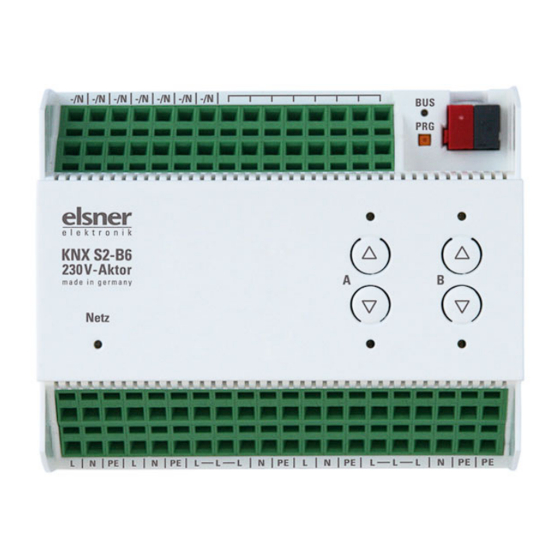
KNX S2-B6 230 V
KNX S1-B2 230 V
Multifunctional Actuators
Technical specifications and installation instructions
Item numbers 70530 (KNX S4-B10 230 V), 70531 (KNX S2-B6 230 V), 70532 (KNX S1-B2 230 V)
1.
Description
The Actuators KNX S4-B10 230 V, KNX S2-B6 230 V and KNX S1-B2 230
V with integrated facade control have multifunctional outputs, pairs of buttons and
monitoring LEDs. Each of the multifunctional outputs can connect to either a drive
with Up/Down control (blinds, awnings, shutters, windows) or two switchable de-
vices (On/Off for light and ventilation). The connected drives and devices can be
operated directly on the actuator or via connected hand switches.
The automation can be specified externally or internally. Internally, there are nu-
merous options available for blocking, locking (e.g. master-slave) and priority defi-
nition (e.g. manual-automatic). Scenes can be saved and called up via the bus
(scene control with 16 scenes per drive).
Binary inputs can be used either for direct operation (e.g. hand switches) or as bus
switches (or also for e.g. alarm notifications). The desired behaviour can be de-
fined precisely through selection of the response times in Standard, Comfort or
Deadman mode.
Functions:
•
Multifunctional outputs each for a 230 V drive (shade, window) or for
connecting two switchable devices (light, fan)
KNX S4-B10: 4 outputs | KNX S2-B6: 2 outputs | KNX S1-B2: 1 output
•
Keypad with button pairs and status LEDs
•
Binary inputs for use as hand switches or as bus switches with variable
voltage (12...80 V DC, 12...240 V AC)
KNX S4-B10: 10 inputs | KNX S2-B6: 6 inputs | KNX S1-B2: 2 inputs
•
Automatic runtime measurement of the drives for positioning (including
fault notification object)
•
Position feedback (movement position, also slat position for blinds)
•
Position storage (movement position) via 1-bit object (storage and call-up
e.g. via button)
•
Control via internal or external automation
•
Integrated shade control for each drive output (with slat tracking
according to sun position for blinds)
•
Scene control for movement position with 16 scenes per drive (also slat
position for blinds)
•
Mutual locking of two drives using zero position sensors prevents
collisions e.g. of shade and window (master–slave)
•
Blocking objects and alarm notifications have different priorities, so safety
functions always take precedence (e.g. wind block)
•
Manual or automatic priority setting via time or communication object
•
5 Safety objects for each channel
•
Short time restriction (movement command blocked) and movement
limitation
Configuration is made using the KNX software ETS 5. The product file can be
downloaded from the ETS online catalogue and the Elsner Elektronik website on
www.elsner-elektronik.de in the "Service" menu.
1.0.1. Scope of delivery
•
Actuator
1.1. Technical Data
Housing
Plastic
Colour
White
Assembly
Series installation on mounting rails
Protection Category
IP 20
Ambient temperature
Operation -20...+45°C, Storage -
55...+90°C
Ambient humidity
max. 95% rH, avoid condensation
Operating voltage
230 V AC, 50 Hz
Current
on Bus: 10 mA
Maximum load
Each terminal contact may be loaded
with a maximum of 10 A.
Minimum current for runtime
AC effective 200 mA
measurement
Actuators KNX S4-B10 230 V, KNX S2-B6 230 V and KNX S1-B2 230 V • Version: 27.05.2020 • Technical changes and errors excepted. • Elsner Elektronik GmbH • Sohlengrund 16 • 75395 Ostelsheim • Germany • www.elsner-elektronik.de • Technical Service: +49 (0) 7033 / 30945-250
Actuators KNX S4-B10 230 V, KNX S2-B6 230 V and KNX S1-B2 230 V
Max. cable length Binary
50 m
inputs
Data output
KNX +/- Bus connector terminal
BCU type
own microcontroller
PEI type
0
Goup addresses
max. 1024
Assignments
max. 1024
KNX S4-B10 230 V (No. 70530):
Dimensions
approx. 107 x 88 x 60 (W × H × D, mm), 6 dividing
units
Weight
approx. 360 g
Power consumption
Operation max. approx. 3.5 W
Standby max. approx. 0.6 W
Outputs
4 × outputs each with 2 connections for drive up/
down or 2 devices, 230 V (PE/N/1/2),
total. max 10 A and max. 4 A per connection
Inputs
10 × binary inputs, universal voltage
(12...80V DC, 12...240 V AC)
Communication
567
objects
KNX S2-B6 230 V (No. 70531):
Dimensions
approx. 107 x 88 x 60 (W × H × D, mm), 6 dividing
units
Weight
ca. 360 g
Power consumption
Operation max. approx, 3.5 W
Standby max. ca. 0.6 W
Outputs
2 × outputs
with 2 connections for drive Up/Down or 2
devices,
230 V (PE/N/1/2),
in total max. 10 A and max. 4 A per connection
Inputs
6 × binary inputs, universal voltage
(12...80 V DC, 12...240 V AC)
Communication
295
objects
KNX S1-B2 230 V (No. 70532):
Dimensions
approx. 53 x 88 x 60 (W × H × D, mm), 3 dividing
units
Weight
approx. 170 g
Power consumption
Operation max. approx, 1.2 W
Output
1 × Output with 2 connections for drive Up/Down
or 2 devices, 230 V (PE/N/1/2),
in total max. 8 A and max. 4 A per connection
Inputs
2 × binary inputs, universal voltage
(12...80 V DC, 12...240 V AC)
Communication
141
objects
The products are compliant with the provisions of EU guidelines.
2.
Installation and start-up
2.1. Installation notes
Installation, testing, operational start-up and troubleshooting should
only be performed by an electrician.
DANGER!
Risk to life from live voltage (mains voltage)!
There are unprotected live components within the device.
•
VDE regulations and national regulations are to be followed.
•
Ensure that all lines to be assembled are free of voltage and take
precautions against accidental switching on.
•
Do not use the device if it is damaged.
•
Take the device or system out of service and secure it against
unintentional use, if it can be assumed, that risk-free operation is no
longer guaranteed.
The device is only to be used for the intended purpose described in this manual.
Any improper modification or failure to follow the operating instructions voids any
and all warranty and guarantee claims.
After unpacking the device, check it immediately for possible mechanical damage.
If it has been damaged in transport, inform the supplier immediately.
The device may only be used as a fixed-site installation; that means only when as-
sembled and after conclusion of all installation and operational start-up tasks and
only in the surroundings designated for it.
Elsner Elektronik is not liable for any changes in norms and standards which may
occur after publication of these operating instructions.
2.2. Safety notice for automatic functions
WARNING!
Risk of injury from automatically moving components!
Parts of the system can be started by the automatic controls
and be a danger to persons.
•
No persons may remain in the travelling range of parts
driven by an electric motor.
•
Adhere to the relevant building regulations.
•
Ensure that the return path/access to the building is not blocked
if spending time outside the building (danger of being locked out).
•
Correctly decommission the system for maintenance and
cleaning work.
If there is a power outage, the system does not work. Therefore, shadings should
be moved to a save position if there are anticipated weather conditions, for exam-
ple, if this has not already been done by the automatic function (product protecti-
on).
If the power supply is removed, the connected drive switches off. When the power
is restored, the consumer remains switched off until a new movement command
is received by the actuator.
2.3. Connection
Follow the guidelines and standards for SELV electric circuits
while installing and cable laying of the KNX connection and
inputs.
Binary inputs:
The connections of the binary inputs including the auxiliary voltage output meet
the requirements for SELV electrical circuits. Mixed installation with non-SELV
electrical circuits or mixing of different auxiliary voltages is not permitted.
2.3.1. Device Design KNX S4-B10 230 V
The device is designed for series installation on mounting rails and occupies 6
width units.
1
2
3
5
7
6
8
9
10
11
12
13
14
15
1) –/N (bridged internally with terminal No. 5). When an external auxiliary voltage
is used (12...80 V DC, 12...240 V AC), one of the –/N terminals is to be assigned
with – or N
2) Free contacts (bridged internally)
3) Programmer LED and programmer buttons (PRG)
4) Bus terminal slot (KNX +/-)
5) –/N (bridged internally with terminal No. 1).
6) Binary inputs 1-6 (1 and 2: two bridged connections)
7) Internal auxiliary voltage + 24 V DC. Only for binary inputs!
Do not assign any external voltage!
8) Binary inputs 7-10
9) Up/Down button pairs and LEDs channel A-D
10)Power LED, Indication of operation mode. See "Indication of operation mode
with the Power LED".
11)Operating voltage input 230 V AC L/N/PE
12)Output A1 - A2: "Up"-"Down" or "Device1"-"Device2", max. 4 A
13)Output B1 - B2: "Up"-"Down" or "Device1"-"Device2", max. 4 A
14)Output C1 - C2: "Up"-"Down" or "Device1"-"Device2", max. 4 A
15)Output D1 - D2: "Up"-"Down" or "Device1"-"Device2", max. 4 A
Nº 12-15 together max. 10 A
16)All terminals L, N, PE of the lower connection strip are bridged internally with
„Main L, N, PE".
1
4
16
Advertisement

Related Manuals for elsner elektronik KNX S4-B10 230 V


Summary of Contents for elsner elektronik KNX S4-B10 230 V
- Page 1 Actuators KNX S4-B10 230 V, KNX S2-B6 230 V and KNX S1-B2 230 V • Version: 27.05.2020 • Technical changes and errors excepted. • Elsner Elektronik GmbH • Sohlengrund 16 • 75395 Ostelsheim • Germany • www.elsner-elektronik.de •...
- Page 2 Actuators KNX S4-B10 230 V, KNX S2-B6 230 V and KNX S1-B2 230 V • Version: 27.05.2020 • Technical changes and errors excepted. • Elsner Elektronik GmbH • Sohlengrund 16 • 75395 Ostelsheim • Germany • www.elsner-elektronik.de •...
Need help?
Do you have a question about the KNX S4-B10 230 V and is the answer not in the manual?
Questions and answers