Advertisement
Quick Links
EN
KNX K4
Actuator for heating and cooling
Technical specifications and installation instructions
Item number 70320
1.
Description
The KNX K4 actuator offers four internal temperature regulators and four output
channels for controlling heating or cooling systems. The temperature regulators can
control both the outputs on the KNX K4 and other climate control system on the
KNX-Bus.
In automatic mode, the temperature regulators are set at nominal temperatures for
different modes. This way, it is easy to switch between the modes, comfort, standby,
eco and building protection. The switch is made via an object e. g. via a manual
switch, time switch or sensor switch outputs in the KNX-System.
The buttons on the device allow for direct manual switching of the connected sys-
tems. LEDs show whether the output channel was manually operated or is running
in an automatic mode.
Functions:
•
4 internal, independent temperature regulators with automatic controls
for the heating and cooling controls (one/two step heating and cooling)
•
4 output channels (230 V AC, 8 Watt per output) with pulse width
modulation control (PWM) for actuators
•
Keypad field 4 buttons and status LEDs
Configuration is made using the KNX software ETS. The product file can be dow-
nloaded from the Elsner Elektronik website on www.elsner-elektronik.de in the
"Service" menu.
1.1. Technical data
Housing
Plastic
Colour
White
Mounting
Series installation on mounting rail
Protection category
IP 20
Dimensions
approx.
53 x 88 x 60
Weight
approx. 110 g
Ambient tempera-
Operation -20...+45°C, storage -55...+90°C
ture
Ambient humidity
max. 95% RH, avoid condensation
Operating voltage
KNX bus voltage
Power
on bus: 10 mA
Outputs
4 x 230 V (OUT/N), not short-circuit-proof.
When connectiong one consumer load per sepa-
rate channel (1 to 4):
Max. load for continuous operation: 8 W per chan-
nel
Max. switch-on current:
nel
Observe the specifications in the data sheet of the
consumer load.
Maximum load
Each terminal contact may be loaded with a maxi-
mum of 10 A.
Data output
KNX +/- bus connector terminal
BCU type
unit's own microcontroller
PEI type
0
Group addresses
max. 254
Assignments
max. 254
Communication
125
objects
KNX K4 actuator • Version: 28.05.2020 • Technical changes and errors excepted. • Elsner Elektronik GmbH • Sohlengrund 16 • 75395 Ostelsheim • Germany • www.elsner-elektronik.de • Technical Service: +49 (0) 7033 / 30945-250
KNX K4 actuator
(W x H x D, mm), 3 modules
1.1 A per chan-
The product conforms with the provisions of EU directives.
2.
Installation and start-up
2.1. Installation notes
Installation, testing, operational start-up and troubleshooting should
only be performed by an electrician.
DANGER!
Risk to life from live voltage (mains voltage)!
There are unprotected live components within the device.
•
VDE regulations and national regulations are to be followed.
•
Ensure that all lines to be assembled are free of voltage and take
precautions against accidental switching on.
•
Do not use the device if it is damaged.
•
Take the device or system out of service and secure it against
unintentional use, if it can be assumed, that risk-free operation is no
longer guaranteed.
The device is only to be used for the intended purpose described in this manual. Any
improper modification or failure to follow the operating instructions voids any and
all warranty and guarantee claims.
After unpacking the device, check it immediately for possible mechanical damage.
If it has been damaged in transport, inform the supplier immediately.
The device may only be used as a fixed-site installation; that means only when as-
sembled and after conclusion of all installation and operational start-up tasks and
only in the surroundings designated for it.
Elsner Elektronik is not liable for any changes in norms and standards which may
occur after publication of these operating instructions.
2.2. Safety notice for automatic functions
WARNING!
Risk of injury from automatically moving components!
Parts of the system can be started by the automatic controls
and be a danger to persons.
•
No persons may remain in the travelling range of parts
driven by an electric motor.
•
Adhere to the relevant building regulations.
•
Ensure that the return path/access to the building is not blocked
if spending time outside the building (danger of being locked out).
•
Correctly decommission the system for maintenance and
cleaning work.
If there is a power outage, the system does not work. Therefore, shadings should be
moved to a save position if there are anticipated weather conditions, for example, if
this has not already been done by the automatic function (product protection).
If the power supply is removed, the connected drive switches off. When the power
is restored, the consumer remains switched off until a new movement command is
received by the actuator.
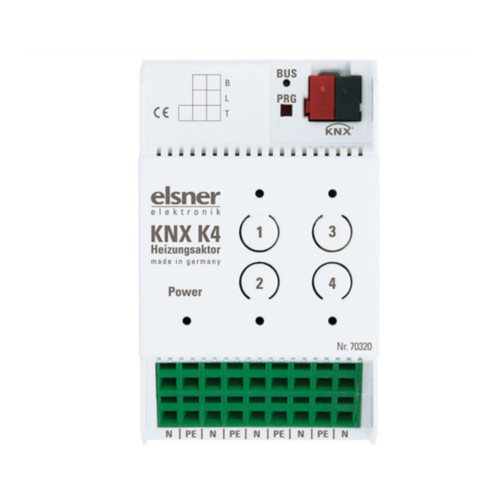
2.3. Device connection and design
1
2
4
3
5
L
PE
N
1) Programming LED and programming buttons (PRG)
2) Bus terminal slot (KNX +/-)
3) Power LED (supply voltage/Bus)
4) Buttons and LEDs outputs 1-4
5) Sample connection: L (230 V) was bridged in this example from
IN 1/2 to IN 3/4.
Actuator on output 4 (OUT 4 | N)
Each terminal contact may be loaded with a maximum of 10 A.
2.4. Notes on mounting and commissioning
Device must not be exposed to water (rain). This could result in the electronics being
damaged. A relative air humidity of 95% must not be exceeded. Avoid condensati-
on.
After the operating voltage has been applied, the device will enter an initialisation
phase lasting a few seconds. During this phase no information can be received or
sent via the bus.
Series installation on
mounting rail
(3 modules)
Internally bridged
cables
Per output max. 8 W
All terminals N or PE of the
lower connection strip are
bridged internally.
Actuator
drive
1
Advertisement

Subscribe to Our Youtube Channel
Related Manuals for elsner elektronik KNX K4


Summary of Contents for elsner elektronik KNX K4
- Page 1 During this phase no information can be received or sent via the bus. KNX K4 actuator • Version: 28.05.2020 • Technical changes and errors excepted. • Elsner Elektronik GmbH • Sohlengrund 16 • 75395 Ostelsheim • Germany • www.elsner-elektronik.de • Technical Service: +49 (0) 7033 / 30945-250...
- Page 2 Do not dispose of it with the household waste! KNX K4 actuator • Version: 28.05.2020 • Technical changes and errors excepted. • Elsner Elektronik GmbH • Sohlengrund 16 • 75395 Ostelsheim • Germany • www.elsner-elektronik.de • Technical Service: +49 (0) 7033 / 30945-250...
Need help?
Do you have a question about the KNX K4 and is the answer not in the manual?
Questions and answers