Advertisement
Quick Links
EN
KNX S2
Actuator for drives up/down
Technical specifications and installation instructions
Item number
70541
1.
Description
With the Actuator KNX S2 with integrated facade control, the drives of shutters,
awnings, blinds or windows are controlled. The connected drives can be directly
operated with the switch pairs of the actuator.
With the potential-free design of the outputs, drives of up to 30 VDC and 230 VAC
can be controlled, as well as other systems (e.g. manual switch input of a motor con-
trol unit).
The automation for the shading or window ventilation is specified externally or in-
ternally. Internally, there are numerous options available for blocking, locking (e.g.
master-slave) and priority definitions (e.g. manual-automatic). Scenes are saved
and called up via the bus (scene control with 16 scenes per drive).
Functions:
•
2 potential-free outputs for drives of shading or windows.
•
Switch panel with switch pairs and status LEDs
•
Position feedback (movement position, also slat position for shutters)
•
Position storage (movement position) via 1-bit object (storage and call-up
e.g. via buttons)
•
Control via internal or external automation functions
•
Integrated shade control for each drive output (with slat tracking
according to sun position for shutters)
•
Integrated window ventilation control
•
Scene control for movement position with 16 scenes per drive (also slat
position for shutters)
•
Mutual locking of two drives using zero position sensors prevents collisions
e.g. of shade and window (master–slave)
•
Blocking objects and alarm reports have different priorities, so that safety
functions always take precedence (e.g. wind block)
•
Manual or automatic control configuration per time or communication
object
•
5 security objects for each channel
•
Brief time limit (movement command blocked) and 2 movement limits
Configuration is made using the KNX software ETS. The product file can be dow-
nloaded from the Elsner Elektronik website on www.elsner-elektronik.de in the
"Service" menu.
1.0.1. Deliverables
•
Actuator
1.1. Technical specifications
Housing
Plastic
Colour
White
Assembly
Series installation on mounting rail according
to DIN 43880
Protection category
IP 20 (after installation in distributor)
Dimensions
approx. 53 x 88 x 60 (W x H x D, mm), 3 modu-
les
Weight
approx. 150 g
Ambient temperature
Operation -5...+45°C, storage -55...+90°C
Ambient humidity
max. 95% RH, avoid condensation
Operating voltage
bus voltage
Current at the bus
approx. 22 mA
Outputs
2 × output up/down potential-free,
up to 30 V DC or 230 V AC,
max. 4 A per output with resistive load
Load/load capacity per
up to 4 A resistive at 30 V DC
output
up to 500 VA at 230 V AC
Data output
KNX +/- bus plug terminal
Group addresses
max. 1024
Assignments
max. 1024
Communication objects
207
Actuator KNX S2 • Version: 01.08.2022 • Technical changes and errors excepted. • Elsner Elektronik GmbH • Sohlengrund 16 • 75395 Ostelsheim • Germany • www.elsner-elektronik.de • Technical Service: +49 (0) 7033 / 30945-250
Actuator KNX S2
The product is compliant with the provisions of EC guidelines.
2.
Installation and commissioning
Installation, testing, operational start-up and troubleshooting should
only be performed by an authorised electrician.
DANGER!
Risk to life from live voltage (mains voltage)!
There are unprotected live components inside the device.
• Inspect the device for damage before installation. Only put undamaged
devices into operation.
• Comply with the locally applicable directives, regulations and provisions for
electrical installation.
• Immediately take the device or system out of service and secure it against
unintentional switch-on if risk-free operation is no longer guaranteed.
Use the device exclusively for building automation and observe the operating inst-
ructions. Improper use, modifications to the device or failure to observe the opera-
ting instructions will invalidate any warranty or guarantee claims.
Operate the device only as a fixed-site installation, i.e. only in assembled condition
and after conclusion of all installation and operational start-up tasks, and only in the
surroundings designated for it.
Elsner Elektronik is not liable for any changes in norms and standards which may
occur after publication of these operating instructions.
2.1. Safety notice for automatic functions
WARNING!
Risk of injury from automatically moving components!
Parts of the system can be started by the automatic controls
and be a danger to persons.
•
No persons may remain in the travelling range of parts
driven by an electric motor.
•
Adhere to the relevant building regulations.
•
Ensure that the return path/access to the building is not blocked
if spending time outside the building (danger of being locked out).
•
Correctly decommission the system for maintenance and
cleaning work.
If there is a power outage, the system does not work. Therefore, shadings should be
moved to a save position if there are anticipated weather conditions, for example, if
this has not already been done by the automatic function (product protection).
If the power supply is removed, the connected drive switches off. When the power
is restored, the consumer remains switched off until a new movement command is
received by the actuator.
2.2. Connection
When installing and laying the cables for the KNX connection,
the regulations and standards governing SELV current circuits
must be observed!
2.2.1. Overview
The device is designed for series installation on mounting rails and occupies 3U.
4
5
7
8
Insulation properties of the clamp groups:
The Actuator KNX S2 is assigned to Overvoltage category III and Pollution degree
2 according to EN60664-1. According to this classification,
between 230 V power cables and FELV 4 kV surge voltage resistance and
between 230 V power cables and SELV 6 kV surge voltage resistance
must be provided. This provision must be observed during the installation.
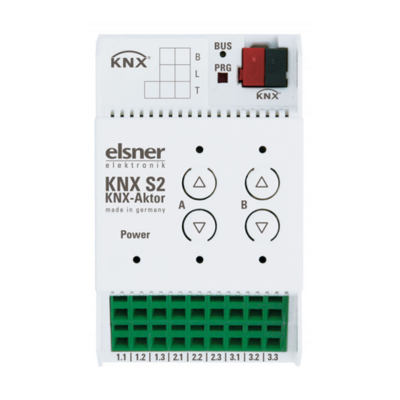
Fig. 1
1 Programmable LED and programm-
2
able buttons (PRG)
1
2 Bus terminal socket (KNX +/-)
3 Up/Down button pairs and LEDs
channel A-B
4 Power LED, operation status indica-
tor. See "Display of operating status
with the power supply LED".
3
5 Output A:
UA (voltage) / A1 (up) / A2 (down),
max. 4 A
6 Output B:
UB (voltage) / B1 (up) / B2 (down),
6
max. 4 A
7 Free clamps 1.1 to 1.3 (internally
bridged), maxi. 10 A per clamp
8 Free clamps 2.1 to 2.3 (internally
bridged), maxi. 10 A per clamp
9
9 Free clamps 3.1 to 3.3 (internally
bridged), maxi. 10 A per clamp
1
Advertisement

Subscribe to Our Youtube Channel
Related Manuals for elsner elektronik KNX S2


Summary of Contents for elsner elektronik KNX S2
- Page 1 1024 Assignments max. 1024 Communication objects Actuator KNX S2 • Version: 01.08.2022 • Technical changes and errors excepted. • Elsner Elektronik GmbH • Sohlengrund 16 • 75395 Ostelsheim • Germany • www.elsner-elektronik.de • Technical Service: +49 (0) 7033 / 30945-250...
- Page 2 ETS by overwriting the 15.15.255 address or by teaching via the pro- gramming button. Actuator KNX S2 • Version: 01.08.2022 • Technical changes and errors excepted. • Elsner Elektronik GmbH • Sohlengrund 16 • 75395 Ostelsheim • Germany • www.elsner-elektronik.de • Technical Service: +49 (0) 7033 / 30945-250...
Need help?
Do you have a question about the KNX S2 and is the answer not in the manual?
Questions and answers