Advertisement
Quick Links
Actuators
KNX S-B4T-UP 230 V and
KNX S-B4T-UP 24 V
Elsner Elektronik GmbH Steuerungs- und Automatisierungstechnik
Herdweg 7 • D-75391 Gechingen • Germany
Phone: +49 (0) 70 56/93 97-0 • Fax: +49 (0) 70 56/93 97-20
info@elsner-elektronik.de • www.elsner-elektronik.de
Technical Data
and Installation Notes
Advertisement

Related Manuals for elsner elektronik KNX S-B4T-UP 230 V


Summary of Contents for elsner elektronik KNX S-B4T-UP 230 V
- Page 1 Actuators KNX S-B4T-UP 230 V and KNX S-B4T-UP 24 V Technical Data and Installation Notes Elsner Elektronik GmbH Steuerungs- und Automatisierungstechnik Herdweg 7 • D-75391 Gechingen • Germany Phone: +49 (0) 70 56/93 97-0 • Fax: +49 (0) 70 56/93 97-20...
-
Page 2: Technical Data
(e. g. wind blocking) Configuration is accomplished by means of the KNX software ETS. The programme file (format VD2) and the manual are ready for download on the Elsner Elektronik website under www.elsner-elektronik.de in the menu "Service". - Page 3 Output: 1 x Drive mechanism 230 V version: max. 500 W, fused with microfuse T6.3 A 24 V version: max. 50 W Inputs: 4 x Binary input (for potential-free contacts) 1 x Temperature sensor input (for T-KTY82) Data output: KNX +/- bus terminal plug BCU type: Own micro controller PEI type:...
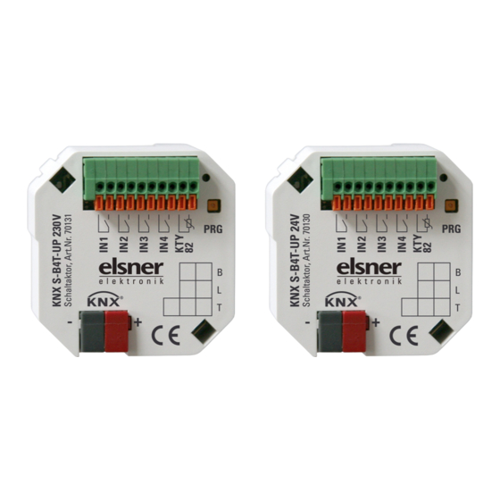
- Page 4 Structure of actuator KNX S-B4T-UP 230 V AC Fig. 1: Front side of KNX S-B4T-UP 230 V Connecting plug terminal binary inputs and temperature sensor Programming LED Programming key (PRG) Inscription space KNX plug terminal +/- Fig. 2: Rear side of KNX S-B4T-UP 230 V...
- Page 5 Structure of actuator KNX S-B4T-UP 24 V DC Fig. 3: Front side of KNX S-B4T-UP 24 V Connecting plug terminal binary inputs and temperature sensor Programming LED Programming key (PRG) Inscription space KNX plug terminal +/- Fig. 4: Rear side of KNX S-B4T-UP 24 V Connecting plug terminal for voltage supply and drive mechanism...
-
Page 6: Installation And Commissioning
The actators must only be operated as stationary system, i.e. only in a fitted state and after completion of all installation and start-up works, and only in the environment intended for this purpose. Elsner Elektronik does not assume any liability for changes in standards after publication of this instruction manual. Connection The actuators are installed in a flush-type socket.