Table of Contents

Advertisement

1.1
Specifications
Control Panel Specifications
Flexible Zone Configuration:
• 8 Fully Programmable Zones
• 38 Access Codes: 32 User, 1 System Master, 2 Partition Master, 2 Duress and 1 maintenance
• Expandable to 32 Zones
• Keypads with zone inputs available (PC/KP5508Z, PC/KP5516Z, PC/KP5532Z, LCD/KPL5500Z)
• Hardwired expansion available using the PC5108 Eight Zone Expansion module, the PC5700 Fire
module, or the PC5720 Fire and DVACS module.
• Wireless expansion available using the PC5132 Wireless Zone Expansion module (up to 32 wireless
zones, 900MHz, True Spread Spectrum Technology, Fully Supervised)
• Normally Closed, Single EOL, or Double EOL zone supervision
• 2-Wire Smoke Input (via PGM2 input)
• 27 Zone Types, 8 Programmable Zone Options
• 2 Partitions
Audible Alarm Output:
• Supervised Bell Output (current limited at 3 amps), 12 V
• Steady or Pulsed Output
EEPROM Memory:
• Will not lose programming or system status on complete AC and Battery failure
Programmable Outputs:
• Up to 14 Programmable Voltage Outputs, 23 programmable options
• One High Current (300 mA) PGM output with 2 wire smoke detector capability on main panel
• Maximum Loop Current is 1.5 mA when the 2-wire smoke detector configuration is used
• One Low Current (50 mA) PGM output on main panel
• Eight Additional Low Current (50 mA) PGM outputs available using the PC5208 module
• Four High Current (1 Amp) PGM outputs Available Using the PC5204 module
• 1 PC5204 Output Fully Supervised for Siren Output
Powerful 1.5 Amp Regulated Power Supply:
• 500 mA Auxiliary Supply, 12 V
• Positive Temperature Coefficient (PTC) components replace fuses
• Supervision for loss of AC Power, Low Battery
• Internal Clock Locked to AC Power Frequency
Power Requirements:
• Transformer = 16.5 VAC, 40VA
• Battery = 12 volt 4 Ah minimum rechargeable sealed lead acid
Remote Keypad Specifications:
• 8 Different Keypads Available:
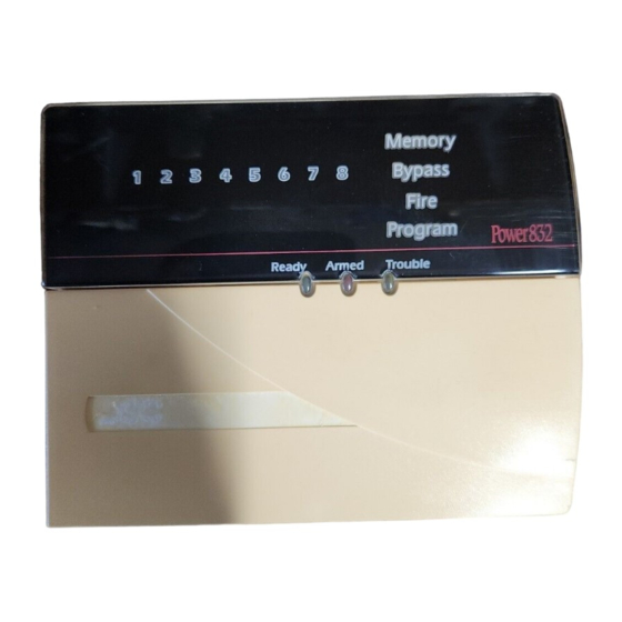
- PC5508 (Z )/KP5508 (Z) 8 Zone LED Keypad
- PC5516 (Z )/KP5516(Z) 16 Zone LED Keypad
• Each Keypad has 5 Fully Programmable Function Keys
• Four Wire (Quad) Connection to Keybus
Digital Communicator Specifications:
• Supports all Major Formats including SIA and Contact ID • Event Initiated Personal Paging
• 3 Programmable Phone Numbers
• Supports LINKS1000 Cellular Communication
• DPDT Line Seizure
• Split Reporting of Selected Transmissions to Each Telephone Number
System Supervision Features
The PC5010 continuously monitors a number of possible trouble conditions including:
• AC Power Failure
• Telephone Line Trouble
• Loss of Internal Clock
• Failure to Communicate
System Introduction
S
E
C
T
DC
• Trouble by Zone
• Low Battery Condition
• AUX Power Supply Fault
• Module Fault (Supervisory or Tamper)
I
O
N
1
DC
- PC5532 (Z )/KP5532 (Z) 32 Zone LED Keypad
- LCD5500 (Z)/ KPL5500 (Z) Alphanumeric Keypad
• Connect up to 8 Keypads
• Built in Piezoelectric Buzzer
• 2 Account numbers
• DTMF and Pulse Dialing
• Anti-jam Feature
• Fire Trouble
• Bell Output Trouble
• Tamper by Zone
1

Advertisement

Table of Contents
loading

Summary of Contents for DSC PC5508

  • Page 1: Section 1 - How To Program 1.1 Specifications

    • Battery = 12 volt 4 Ah minimum rechargeable sealed lead acid Remote Keypad Specifications: • 8 Different Keypads Available: - PC5508 (Z )/KP5508 (Z) 8 Zone LED Keypad - PC5532 (Z )/KP5532 (Z) 32 Zone LED Keypad - PC5516 (Z )/KP5516(Z) 16 Zone LED Keypad - LCD5500 (Z)/ KPL5500 (Z) Alphanumeric Keypad •...
  • Page 2: Additional Devices

    A maximum of eight (8) keypads can be connected to the control panel and can be any combination of the following listed. Different keypads (with function keys) can be used for different size systems; 8 zone, 16 zone and 32 zone. PC5508/PC5508Z PC5516 /PC5516Z PC5532 / PC5532Z...
  • Page 3: Pc5100 Addressable Service Interface Module

    WLS908 Wireless Panic Pendant The wireless Panic Pendant can be used in conjunction with the PC5132 Wireless Receiver to include personal wireless protection. The unit comes with 1 mini 12V battery. The battery is not user changeable. WLS909 Wireless Key The wireless key can be used in conjunction with the PC5132 wireless receiver to include a simple and mobile method of arming and disarming the system.
  • Page 4: Pc5700 Fire Module

    1.2.10 PC5700 Fire Module A zone expansion module with four general purpose zone inputs, two Class A supervisory waterflow zone inputs, ground fault detection and dual-supervised telephone line inputs. 1.2.11 PC5720 Fire/Printer/DVACS Module A zone expansion module with five general purpose zone inputs, two Class A supervisory waterflow zone inputs, ground fault detection, and connections for interfacing with either a serial printer or a DVACS communications network.
  • Page 5: Section 2 - Getting Started

    Getting Started The following sections provide a complete description of how to wire and configure devices and zones. Installation Steps The following steps are provided to assist with the installation of the panel. It is suggested that you read over this section briefly to get an overall understanding of the order of installation.
  • Page 6: Terminal Descriptions

    Terminal Descriptions AC Terminals - AC The panel requires a 16.5 volt, 40 VA transformer. Connect the transformer to an unswitched AC source and connect the transformer to these terminals. Do not connect the transformer until all other wiring is complete . Battery Connection The battery is used to provide back up power in the event of an AC power failure and to provide additional current when the panel demands exceed the power output of the transformer, such as when...
  • Page 7: Keybus Operation And Wiring

    Connect the PC5010 and modules which use the telephone line(s) in the following order: For example, if you are installing a PC5010 with a LINKS1000 and a PC5928 Intercom module, connect the incoming line to the LINKS1000, then from the LINKS1000 to the PC5010, then from the PC5010 to the PC5928 Intercom and then from the PC5928 to the house telephones Ensure the plugs and jacks meet the dimension, tolerance and metallic plating requirements of 47 C.F.R.
  • Page 8: Assigning Zones To Zone Expanders

    • PC5132 Wireless Module: 125 mA • PC5516 Keypad: 45 mA • PC5100 Addressable Device Interface Module: 40 mA • PC5508 Keypad: 45 mA • Escort5580 Module: 150 mA • LCD5500Z Keypad: 85 mA • PC5928 Audio Interface Module: 65 mA •...
  • Page 9: Keypad Assignment

    Keypad Assignment There are 8 available slots for keypads. LED keypads by default are always assigned to slot 1 while the LCD5500Z is always assigned to slot 8. Keypads can each be assigned to a different slot (1 to 8) which offers two advantages.
  • Page 10: Removing Modules

    Removing Modules If a module is no longer required on the system the panel must be told to no longer supervise the module. To do this remove the module from the Keybus and perform the Enable supervision function again ( See Section 2.7 “Enable Supervision”).
  • Page 11: Fire Zone Wiring - 4 Wire Smoke Detectors

    2.9.4 Fire Zone Wiring - 4 wire Smoke Detectors All zones defined as Fire (See Section 5.1 “Zone Definitions”) must be wired according to the following diagram: For a complete description of how fire zones operate, see Section 5.1 “Zone Definitions”. 2.9.5 Fire Zone Wiring - 2 wire Smoke Detectors If PGM2 has been programmed for 2 Wire Smoke Detector connection (See Section 5.10 “PGM Output”),...
  • Page 12: Keypad Zones

    2.10 Keypad Zones Keypads with zone inputs can be connected to devices such as door contacts. This saves you from running wires back to the control panel for every device. To install the keypad, open the keypad plastic by removing the screw at the bottom of the unit. Locate the five terminals on the keypad circuit board.
  • Page 13: Section 3 - Keypad Commands

    Keypad Commands All keypads provide complete information and control of the alarm panel. The panel can be completely programmed via any keypad on the system. LED keypads provide function indicator lights and individual zone indicator lights for the alarm circuits. The LCD keypad provides function indicator lights and word descriptions for zone status. The following sections describe how to arm, disarm and perform other keypad functions.
  • Page 14: Auto Bypass

    Auto Bypass When the system is armed and any zone or zone(s) on the system have been programmed as Stay/Away the panel will immediately turn on the ‘Bypass’ light. It will then monitor all zones programmed as Delay 1 and Delay 2. If no delay type zone is violated by the end of the exit delay the panel will bypass all Stay/ Away type zones.
  • Page 15: Alarm Memory

    A description of the various troubles are as follows: Trouble [1] - Service Required This light will be on if any of the following trouble conditions are detected by the control panel; Low Battery, Bell Circuit Trouble, General System Trouble, General System Tamper, General System Supervisory, PC5204 Low Battery and PC5204 AC Failure.
  • Page 16: Door Chime On/Off

    [ ]+[4] Door Chime On/Off If enabled the keypad will beep 5 times rapidly when a zone is tripped and restored. The panel will only do this for zones with the Door Chime attribute enabled and if the door chime feature is enabled (See Section 5.2 “Zone Attributes”) .
  • Page 17: User Functions

    How to erase Access Code: Select the code to be erased and press [ ]. [ ]+[6] User Functions This keypad command can be used to program several different functions. The following are the items programmable: [1] - Time and Date [4] - System Test [6] - User Initiated Call-Up [2] - Auto-Arm Enable *...
  • Page 18: Command Output Functions

    [ ]+[7] Command Output Functions There are four output functions available to the user. Each function can be performed when the system is either armed or disarmed. [ ] [7] [1-4] – Command Output Option #1-4: Press [ ] [7] [1-4] [Access Code, if required] to activate outputs programmed as PGM output option [19]- [22].
  • Page 19: Function Key Options

    “Chime” - Door Chime On/Off Pressing the key will toggle the Door Chime feature ON or OFF. One solid beep means the feature has been disabled, three short beeps means it has been enabled. “Reset” - Reset Smoke Detectors Pressing this key will cause the panel to activate for 5 seconds any output programmed as Sensor Reset. In addition two wire smoke detectors connected to PGM2 will also be reset (See Section 3.4 “[ ] Commands, [ ][7][2]”).
  • Page 20: Global And Partition Keypad Operation

    [14] - [ ]+[7]+[2] Smoke Detector Reset This function key provides the user with a simple method for activating a PGM output programmed as either option [03] Sensor Reset or [20] Command Output option 2. [15] - General Voice Prompt Help This feature can only be programmed if both the Escort5580 and the PC5928 Audio Matrix module are being used.
  • Page 21: Section 4 - How To Program

    How to Program The following section of the manual describes how to enter Installer Programming and how to program the various sections. It is extremely important that you read the following section of the manual to completely understand how to program the panel.
  • Page 22: Programming Toggle Option Sections

    If you are using a pulse format, a decimal zero [0] does not transmit. Programming a zero [0] tells the panel not to send any pulses for that digit. Decimal zero [0] is a filler digit. To make a zero [0] transmit, it must be programmed as a Hexadecimal ‘A’.
  • Page 23: Section 5 - Program Description

    Program Descriptions The following section explains all the programmable features including how the feature operates, options that pertain to the feature and a summary of program locations that require programming. Zone Definitions These sections will allow you to select how each of the 32 zones will operate. Each zone requires a 2 digit entry.
  • Page 24: Assigning Keypad Zones

    [09] 24 Hour Supervisory Zone If this zone is violated, whether armed or disarmed, the panel will report to the central station, and log the zone fault. Do not wire 24-Hour Supervisory zones on keypad zone terminals. [10] 24 Hour Supervisory Buzzer Zone Whether armed or disarmed, when this zone type is violated the panel will immediately latch the keypad buzzer until a valid user code is entered and will communicate immediately to the central station.
  • Page 25: Communicator - Dialing

    Swinger Shutdown Enable Determines if the panel will shut down the communicator for the zone after the swinger limit is reached (See Section 5.17 “Swinger Shutdown”) . Transmission (TX) Delay Enable Determines if the panel will delay communicating the alarm reporting code to the central station (See Section 5.18 “Transmission Delay”).
  • Page 26: Communicator - Account Numbers

    Communicator - Account Numbers There are two Partition Identifier Codes (or Account Numbers) programmable, one for each Partition. The Account Number is used by central station to determine which panel is calling. If the panel is programmed as two Partitions both Account Numbers must be programmed. The panel will report to the central station by Partition.
  • Page 27: Pager Format

    If the SIA Sends Automatic Reporting Codes option is disabled the panel will operate as follows: 1. If the reporting code for an event is programmed as [00] or [FF] the panel will not attempt to call central station. 2.If the reporting code for an event is programmed as anything from [01] to [FE] the panel will send the programmed reporting code.
  • Page 28: Openings

    A Partial Closing Reporting Code will be transmitted if a Partition is armed with zones manually bypassed. The code will also be transmitted if a Partition Auto Arms with zone(s) in violation. A Special Closing Reporting Code will be transmitted if the Partition(s) is armed using any of the following methods: •...
  • Page 29: Test Transmissions

    The Auxiliary Power Supply Trouble Alarm Reporting Code will be transmitted if the AUX output is shorted. The AUX output control incorporates a fuseless design. When excessive current is drawn the panel will automatically shut off the output. The panel will constantly check the AUX output and when the excessive current draw is removed the panel will reset the output and transmit an Auxiliary Power Supply Trouble Restoral Reporting Code.
  • Page 30: Downloading

    ○ ○ ○ ○ ○ ○ ○ ○ ○ ○ ○ ○ ○ ○ ○ ○ ○ ○ ○ ○ ○ ○ ○ ○ ○ ○ ○ ○ ○ ○ ○ ○ ○ ○ ○ ○ ○ ○ ○ ○ ○ ○ ○ ○ ○ Reporting Codes ..................
  • Page 31: Pgm Outputs

    Keypads can be assigned to work on either partition or can be assigned for Global operation (See Section 2.6 “Keypad Assignment”). Each partition can be programmed to report using a different Account Number (See Section 5.5 “Communicator - Account Numbers”). Some of the Programmable Output options are also selectable by Partition (See Section 5.10 “PGM Outputs”).
  • Page 32 [10] Latched System Event (Strobe Output) The output will activate when any of the selected system events (alarms) occur on the system. In the armed state, the output will deactivate only once the system is disarmed. If an alarm activates this output in the disarmed state, the output will deactivate if a user enters a valid access code while the Bell Cut-off timer is counting down.
  • Page 33: Pgm Output Attributes

    5.10.2 PGM Output Attributes In addition to programming the output type, you must also program the PGM output attributes for each output. PGM output options [09] “System Trouble” and [10] “Latched System Event” have their own unique set of attributes listed below the description of each output type. PGM output options [01], [03], [05]-[08], [11]-[24] have the following attributes: Attribute ON Partition 1 controls event...
  • Page 34: Siren

    5.12 Siren The siren will silence after the number of minutes programmed for the Bell Cut-off time have passed. The panel supervises the Bell output. If an open condition is detected, the panel will immediately indicate a trouble condition by beeping the keypad twice every 10 seconds to alert the owner of the problem. The panel can send a Bell Circuit Trouble and Trouble Restoral reporting codes to indicate the situation (see Section 5.8 “Communicator –...
  • Page 35: Entry/Exit Delay Options

    5.15 Entry/Exit Delay Options Upon arming, the panel will begin the exit delay. If Audible Exit Delay is enabled the keypad will beep every second until the exit delay expires. The keypad will beep rapidly for the last 10 seconds of exit delay to warn the user the system is about to arm.
  • Page 36: Transmission Delay

    Swinger Shutdown will be reset when the panel is armed or every day at midnight. Once reset, the panel will again communicate normally. ○ ○ ○ ○ ○ ○ ○ ○ ○ ○ ○ ○ ○ ○ ○ ○ ○ ○ ○ ○ ○ ○ ○ ○ ○ ○ ○ ○ ○ ○ ○ ○ ○ Swinger Shutdown Limit (Alarms/Tampers/Maintenance) Section [370] ○...
  • Page 37: Keypad Blanking

    5.23 Keypad Blanking If the Keypad Blanking Option is enabled the panel will turn off all lights and LCDs on the keypads if no key is pressed for 30 seconds. The keys, however, will remain backlit. The panel will turn the lights and LCDs back on if entry delay begins or an audible alarm occurs. The lights and LCDs will also come on if a key is pressed or, if the Code Required to Restore Blanking Option is enabled, a valid User Code is entered.
  • Page 38: Using The Links As A Redundant Communicator

    5.26.3 Using the LINKS as a Redundant Communicator The panel can be programmed to call using both the land line and the LINKS1000 cellular communicator when an event occurs. To program this select both the phone number and the LINKS options for the Communicator Call Direction Options for the event.
  • Page 39: On-Site Printer

    In addition, all touch tone phones on the premise also become fully functional keypads. This may help reduce the cost of the overall installation because additional keypads (and labour in running wires) can be eliminated. The Escort5580 will also act as a tutor for the system. By speaking in clear, easy to understand sentences it helps guide a user through functions they may otherwise have difficulty with.
  • Page 40: Factory Default Main Panel (Software) And Other Modules40

    5.31.2 Factory Default Main Panel (Software) and other Modules Step 1 - Enter the Installer Programming mode. Step 3 - Enter the Installer Code. Step 2 - Enter Program Section [XXX]. Step 4 - Enter Program Section [XXX] again. The panel will take a few seconds to perform the default. When the keypad is again operational the default is complete.
  • Page 41: Appendix A - Contact Id

    Appendix A Contact ID The Partition ID Codes must be 4 digits. All reporting codes must be 2 digits. The following is a list of Contact ID reporting codes. The first digit (in parentheses) will automatically be sent by the control.
  • Page 42: Appendix B - Sia Format

    Appendix B SIA Format Level 2 (Hardcoded) The SIA communication format used in this product follows the level 2 specifications of the SIA Digital Communica- tion Standard - January 1996. This format will send the Account Code along with its data transmission. At the receiver, the transmission would look similar to this example: N Ri01 BA 01...
  • Page 43 If telephone lines are used to transmit alarms, they may be out of service or busy for certain periods of Any products returned to DSC which have the Installer’s Lockout option enabled and time. Also an intruder may cut the telephone line or defeat its operation by more sophisticated means which may be difficult to detect.
  • Page 44 © 1997 Digital Security Controls Ltd. 1645 Flint Road, Downsview, Ontario, Canada M3J 2J6 Tel. (416) 665-8460 • Fax (416) 665-7498 • Tech. Line 1-800-387-3630 Printed in Canada 29002642 R0...
  • Page 45 Installation Manual PC5O1O Version 2.O DLS-1 version 6.4 or later WARNING This manual contains information on limitations regarding product use and function and information on the limitations as to liability of the manufacturer. The entire manual should be carefully read.
  • Page 46 VIS: L’étiquette de l’Industrie Canada identifie le matériel homologué. Cette étiquette certifie que le matériel est conforme à certaines normes de protection, d’exploitation et de sécurité des réseaux de télécommunications. Industrie Canada n’assure toutefois pas que le matériel fonctionnera à la satisfaction de l’utilisateur. Avant d’installer ce matériel, l’utilisateur doit s’assurer qu’il est permis de le raccorder aux installations de l’entreprise locale de télécommunication.
  • Page 47: Table Of Contents

    Table of Contents PC5010 Control Panel Hook-up Diagram ........ii Viewing Programming ............22 4.5.1 LED Keypads ..............22 Section 1 - How to Program 4.5.2 LCD Keypad ............... 22 Specifications ............... 1 Additional Devices ............... 2 Section 5 - Program Description 1.2.1 Keypads ................
  • Page 48 Hookup Diagram P C 5 0 1 0 C O N T R O L P A N E L...

Table of Contents