DSC LCD5500Z Installation Instructions Manual
Hide thumbs
Also See for LCD5500Z:
- Manual (48 pages) ,
- Instruction manual (44 pages) ,
- Quick manual (4 pages)
Table of Contents
Advertisement
LCD5500Z / PKP-LCD
v3.x Installation Instructions
Introduction
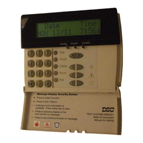
The LCD5500Z / PKP-LCD keypad displays system
status using an LCD screen. The keypad can be
used on PowerSeries security systems with up to 64
zones.
Specifications
• Connects to control panel via 4-wire Keybus
• One keypad zone input
• Current draw: 45mA (standby); 85mA (max)
• Five programmable function keys
• Ready (green), Armed (red) and Trouble (yellow)
status lights
Installation
Unpacking
The LCD5500Z / PKP-LCD package includes the
following parts:
• One LCD5500Z / PKP-LCD keypad
• Four mounting screws
• One set of Fire, Auxiliary and Panic key labels
Mounting
You should mount the keypad where it is accessible
to designated points of entry and exit. Once you
have selected a dry and secure location, perform the
following steps to mount the keypad:
1. For the PKP-LCD, remove the end-cap located at
the bottom of the keypad. This can be done by gently
inserting a small flathead screwdriver into the groove
separating the end-cap and the rest of the keypad.
2. Remove the keypad backplate by removing the
two screws located at the base of the unit.
3. Secure the keypad backplate to the wall in the
desired location. Use the screws provided.
4. Before attaching the keypad to its backplate,
complete the keypad wiring as described in the
next section.
Wiring
1. Before beginning to wire the unit, ensure that all
power (AC transformer and battery) is
disconnected from the control panel.
2. Connect the four Keybus wires from the control
panel (red, black, yellow and green) to the keypad
terminals (R B Y G). Consult the diagram below:
WARNING: Please refer to the System Installation
Manual for information on limitations regarding
product use and function and information on the
limitations as to liability of the manufacturer.
TM
Advertisement
Table of Contents

Related Manuals for DSC LCD5500Z


Summary of Contents for DSC LCD5500Z
-
Page 1: Specifications
LCD5500Z / PKP-LCD v3.x Installation Instructions Introduction The LCD5500Z / PKP-LCD keypad displays system 2. Remove the keypad backplate by removing the status using an LCD screen. The keypad can be two screws located at the base of the unit. - Page 2 I _ ___I _ ___I _ ___I _ ___I _ ___I _ ___I _ ___I _ ___I _ ___I _ ___I _ ___I _ ___I _ ___I _ ___I then generate a fault when a keypad supervisory signal is not present. There are eight available slots [065] Fire Alarm Label for keypads. LCD5500Z / PKP-LCD keypads are Default Default Default...
- Page 3 [070] First User Display Mask Default Default Default Default Default Option ON Option OFF I___I Option 1 Hold [P] Key Prompt ON Hold [P] Key Prompt OFF I___I Option 2 Zone Bypassing Prompt ON Zone Bypass Prompt OFF I___I Option 3 Troubles Prompt ON Troubles Prompt OFF I___I Option 4...
- Page 4 [075] Fourth User Display Mask Default Option ON Option OFF I___I Option 1 User-initiated Callup Prompt ON User-initiated Callup Prompt OFF I___I Option 2 Last Code to Disarm/Arm Prompt ON Last Code to Disarm/Arm Prompt OFF I___I Option 3 Walk Test Prompt ON Walk Test Prompt OFF I___I Option 4 Command Output #1 Prompt ON...
- Page 5 [103] Partition 3 Label Default P a r t i t i o n _ 3 _ _ _ _ _ I____I____I____I____I____I____I____I____I____I____I____I____I____I____I [104] Partition 4 Label Default P a r t i t i o n _ 4 _ _ _ _ _ I____I____I____I____I____I____I____I____I____I____I____I____I____I____I [105] Partition 5 Label Default...
- Page 6 [127] Partition 2 Command Output #4 Label Default Command_O/P_4_ I____I____I____I____I____I____I____I____I____I____I____I____I____I____I [128] Partition 3 Command Output #1 Label Default Command_O/P_1_ I____I____I____I____I____I____I____I____I____I____I____I____I____I____I [129] Partition 3 Command Output #2 Label Default Command_O/P_2_ I____I____I____I____I____I____I____I____I____I____I____I____I____I____I [130] Partition 3 Command Output #3 Label Default Command_O/P_3_ I____I____I____I____I____I____I____I____I____I____I____I____I____I____I [131] Partition 3 Command Output #4 Label Default Command_O/P_4_...
- Page 7 [140] Partition 6 Command Output #1 Label Default Command_O/P_1_ I____I____I____I____I____I____I____I____I____I____I____I____I____I____I [141] Partition 6 Command Output #2 Label Default Command_O/P_2_ I____I____I____I____I____I____I____I____I____I____I____I____I____I____I [142] Partition 6 Command Output #3 Label Default Command_O/P_3_ I____I____I____I____I____I____I____I____I____I____I____I____I____I____I [143] Partition 6 Command Output #4 Label Default Command_O/P_4_ I____I____I____I____I____I____I____I____I____I____I____I____I____I____I [144] Partition 7 Command Output #1 Label Default Command_O/P_1_...
-
Page 8: Limited Warranty
LIMITED WARRANTY Digital Security Controls Ltd. warrants the original purchaser that for a period which are not identified with DSC's product label and lot number or serial of twelve months from the date of purchase, the product shall be free of number;...
Need help?
Do you have a question about the LCD5500Z and is the answer not in the manual?
Questions and answers