Table of Contents
Advertisement
Quick Links
TABLE OF CONTENTS
Features .................................................................................................................................................. 3
Specifications .......................................................................................................................................... 3
Mounting the Panel ................................................................................................................................. 4
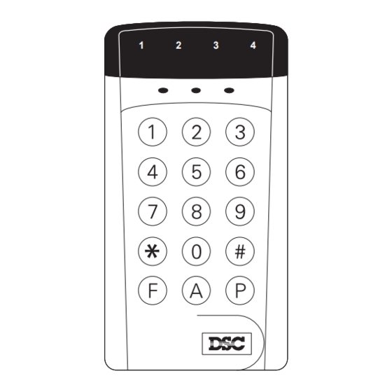
Mounting the Keypad .............................................................................................................................. 4
Wiring ...................................................................................................................................................... 5
Burglary Zone Wiring .............................................................................................................................. 5
Auxiliary Power Connection .................................................................................................................... 5
PGM Terminal Connections .................................................................................................................... 5
STR Terminal Connection ....................................................................................................................... 5
KEY Terminal Connection ....................................................................................................................... 6
AC Power Wiring ..................................................................................................................................... 6
Battery Connection ................................................................................................................................. 6
Telephone Line Wiring ............................................................................................................................ 6
Introduction ............................................................................................................................................. 7
Master Code ............................................................................................................................................ 7
Installer's Programming Code ................................................................................................................ 7
Arming ..................................................................................................................................................... 7
Auto-Bypass/Stay-Away Arming ............................................................................................................. 7
At-Home Arming ...................................................................................................................................... 7
Disarming ................................................................................................................................................ 8
∗
[
]+[0]:Quick-Arm .................................................................................................................................. 8
∗
[
]+[1]+[Access Code]: Zone Bypassing ............................................................................................. 8
∗
[
]+[2]:Display Trouble Conditions ....................................................................................................... 8
∗
[
]+[3]:Display Alarm Memory .............................................................................................................. 9
∗
[
]+[4]:Bell Test ..................................................................................................................................... 9
∗
[
]+[5]+[Master Code]: Program Access Codes ................................................................................. 9
∗
[
]+[6]:Door Chime On/Off .................................................................................................................... 9
∗
[
]+[7]:Utility Output Command ............................................................................................................ 9
∗
[
]+[8]+[Installer's Code]: Installer's Programming Command .......................................................... 10
∗
[
]+[9]+[Access Code]: At-Home Arming ........................................................................................... 10
Keypad Zones ....................................................................................................................................... 10
Adjusting the Keypad Sounder Tone and Backlighting ....................................................................... 10
∗
] Commands ...................................................................................... 8
3
4
7
1
Advertisement
Table of Contents

Related Manuals for DSC PC560


Summary of Contents for DSC PC560
-
Page 1: Table Of Contents
TABLE OF CONTENTS INTRODUCTION Features ..............................3 Specifications ............................3 INSTALLATION Mounting the Panel ..........................4 Mounting the Keypad ..........................4 Wiring ..............................5 Burglary Zone Wiring ..........................5 Auxiliary Power Connection ........................5 PGM Terminal Connections ........................5 STR Terminal Connection ........................5 KEY Terminal Connection ........................ - Page 2 PROGRAMMING GUIDE Sections [05] through [07]: Enabling System Functions ..............11 HEX Data Programming ........................11 Resetting Programming to the Factory Default Settings ............... 12 PROGRAMMING SECTIONS [01] Zone Definitions ........................... 13 [02] System Times ..........................14 [03] Installer’s Code ..........................14 [04] Programmable Output Options (PGM Terminal) ................
-
Page 3: Introduction Features
INTRODUCTION FEATURES SPECIFICATIONS • Fully featured security system with Trouble PC560 Control Panel Supervision, Alarm Memory, Master Code and 3 • Four fully programmable zones programmable Access Codes, Quick-Arming and • Zones are End-of-Line Resistor supervised At-Home Arming, Door Chime, 3 one-touch Keypad •... -
Page 4: Installation
It is recommended that appropriate wall anchors be used when securing the panel to drywall, plaster, concrete, brick or other similar surfaces using #8x1” round headed screws (or equivalent). Press the PC560 Control Panel onto the nylon mounting studs. Pull all cables into the cabinet and prepare them for connection. -
Page 5: Wiring
Wiring NOTE: Complete all wiring to the control panel before applying battery or AC power. If the neutral in the main supply is not readily identifiable, then an appropriate disconnect device that has a contact separation of at least 3mm and disconnects both poles simultaneously, must be used. In order to comply with safety requirement IEC950, ensure that when the mains cabling enters the alarm panel, it is securely clamped to prevent it from being removed. -
Page 6: Key Terminal Connection
KEY Terminal Connection The KEY terminal may be programmed for keyswitch operation or for use as a tamper zone. Refer to the Hook-up Diagram in the back of this manual for instructions on wiring the KEY terminal. AC Power Wiring Complete all wiring to the control panel before connecting AC power or the battery. -
Page 7: Keypad Functions
Master Code A default Master Code “1234” is factory programmed into the PC560. The Master Code is used to arm and disarm the panel, to silence the sounder after an alarm, and to program additional Access Codes. The Master ∗... -
Page 8: Disarming
]+[2]: Display Trouble Conditions The PC560 continuously monitors a number of trouble conditions. If one of these conditions occur, the keypad “System” light will come ON and the sounder will sound two short beeps every 10 seconds. To silence the sounder, press the [#] Key;... -
Page 9: Display Alarm Memory
∗ ]+[3]: Display Alarm Memory Alarms caused during the previous armed period are stored in memory. To display the zones that went into ∗ alarm, enter [ ][3]. The “System” light will FLASH and the alarms will be displayed on the flashing zone lights. Note that the alarm memory will be cleared the next time the system is armed. -
Page 10: Installer's Code]: Installer's Programming Command
∗ ]+[8]+[Installer’s Code]: Installer’s Programming Command ∗ The PC560 is programmed from the keypad by using commands in the [ ][8][Installer’s Code] section. These commands are described in detail in the Programming Section of this manual. The default Installer’s Code is [0560]. -
Page 11: Programming Guide
PROGRAMMING GUIDE ∗ With the panel disarmed, enter [ ][8][Installer’s Code]. The panel can only be programmed while it is disarmed. The default Installer’s Code is [0560]. The Installer’s Code should be changed after the system is installed; refer to Programming Section [03]. When the Installer’s Programming Command is entered, the “Armed”... -
Page 12: Resetting Programming To The Factory Default Settings
7 Remove the connection between the PGM and Zone 1 terminals 8 Re-connect original wiring to the PGM and Zone 1 terminals 9 Restore power to the PC560; the Programming Sections have now been restored to the factory default settings... -
Page 13: Programming Sections
PROGRAMMING SECTIONS [01] Zone Definitions Enter four 2-digit numbers in this section to determine the operating characteristics of each zone. Zone Definitions: Digit 1 The first digit of each Zone Definition determines each zone’s audible alarm characteristics. When programmed as [0] Audible, the siren will sound on alarm; when programmed as [1] Silent, the siren will not sound on alarm. Note that zone response times are factory set at 500 ms. -
Page 14: System Times
[02] System Times Three system times are programmed in Section [02]; each time requires a 3-digit number. Do not press the [#] Key during data entry. [1] Entry Delay (001 to 255 seconds) The Entry Delay determines the amount of time permitted between the activation of a Delay Zone and the disarming of the system. -
Page 15: First System Option Code
After one or two rings, the downloading computer must hang-up the line and then place another call to the PC560 within 60 seconds. The PC560 will then answer the second call on the first ring. Note that the “double call” technique is the only means of connecting to the downloading computer. -
Page 16: Third System Option Code
[07] Third System Option Code Refer to Section [05] for programming information. LIGHT [1] • ON = Restorals reported on Disarming* OFF = Restorals reported on Bell Timeout** [2] • OFF = For Future Use [3] • OFF = For Future Use For Future Use [4] •... -
Page 17: Maintenance And Priority Codes
[13] Maintenance and Priority Codes Maintenance Codes are transmitted to indicate various trouble conditions and their restorals; Priority Codes are used to indicate the activation of the [F], [A] and [P] keys. Program a 2-digit code for each of the following conditions: •... -
Page 18: For The Record
FOR THE RECORD Customer ___________________________________________________________________________________ Address ___________________________________________________________________________________ ___________________________________________________________________________________ Phone ________________________________ Installation Date ____________________________ CONTACTS Name ________________________________ Phone ________________________ Name ________________________________ Phone ________________________ Name ________________________________ Phone ________________________ ZONE INFORMATION Zone Type Protected Area ____________________ _______________________________________________________ ____________________ _______________________________________________________ ____________________ _______________________________________________________ ____________________ _______________________________________________________ Entrance Delay ____________________________ Exit Delay ________________________________ Bell Cutoff ________________________________... -
Page 19: Programming Worksheets
PROGRAMMING WORKSHEETS [01] Zone Definitions Page 13 NOTE: When defining zones, assign Delay Zones starting with Zone 1, then Zone 2, and so on. Then, assign the other zone types to the remaining zones in any order desired. Digit 1 Digit 2 Default [0] Audible... - Page 20 [06] Second System Option Code Page 15 Default Zone Light ON Zone Light OFF Zone Light 1 DTMF dialing Pulse dialing Zone Light 2 1400Hz Handshake 2300Hz Handshake Zone Light 3 DLS Answer enabled DLS Answer disabled Zone Light 4 Ringback enabled Ringback disabled [07]...
- Page 21 [11] Zone Alarm and Restoral Reporting Codes Page 16 For single digit reporting codes, enter [0] as the second digit. ∗ ∗ Zone 1 Alarm Enter [ ] (HEX A) to transmit a “0” (zero = 10 pulses) Zone 2 Alarm Zone 3 Alarm Zone 4 Alarm Tamper Alarm...
- Page 22 [13] Maintenance and Priority Codes Page 17 [P] Key Alarm [A] Key Alarm [F] Key Alarm Battery Trouble Battery Restore Periodic Test Code Police Code [14] Downloading Access Code Page 17 Default 0 5 0 5 This code allows the panel to confirm that a valid downloading computer is requesting access to the panel.
-
Page 23: Hook-Up Diagram
HOOK-UP DIAGRAM... -
Page 24: Limited Warranty
Installer’s Lockout • damage incurred in shipping or handling; Any products returned to DSC which have the Installer’s Lockout • damage caused by disaster such as fire, flood, wind, earthquake or option enabled and exhibit no other problems will be subject to a lightning;... - Page 25 WARNING Smoke Detectors Please Read Carefully Smoke detectors that are a part of this system may not properly alert occupants of a fire for a number of reasons, some of which follow. The smoke detectors Note to Installers may have been improperly installed or positioned. Smoke may not be able to This warning contains vital information.
- Page 26 © 1997 Digital Security Controls Ltd. 1645 Flint Road, Downsview, Ontario, Canada M3J 2J6 Printed in Canada 29000870 R3...
-
Page 27: Installation Manual
Installation Manual PC56O Software Version 1.O DLS-1 V5.5 and up • W A R N I N G • This manual contains information on limitations regarding product use and function and information on the limitations as to liability of the manufacturer. The entire manual should be carefully read.
Need help?
Do you have a question about the PC560 and is the answer not in the manual?
Questions and answers