
Subscribe to Our Youtube Channel
Related Manuals for Beckhoff EP6224


Summary of Contents for Beckhoff EP6224
- Page 1 Documentation | EN EP6224 and EP6228 IO-Link Master with protection class IP67 2023-04-17 | Version: 2.3...
-
Page 3: Table Of Contents
Tightening torques for plug connectors................ 60 5.1.7 Functional earth (FE) ....................... 60 Connections ............................ 61 5.2.1 Supply voltages........................ 62 5.2.2 EtherCAT ......................... 65 5.2.3 IO-Link.......................... 67 5.2.4 Digital inputs: EP6224-0042 - X01, X02, X05, X06............ 70 EP6224 and EP6228 Version: 2.3... - Page 4 Version identification of EtherCAT devices ................... 127 9.3.1 General notes on marking.................... 127 9.3.2 Version identification of IP67 modules ................ 128 9.3.3 Beckhoff Identification Code (BIC) ................. 129 9.3.4 Electronic access to the BIC (eBIC)................ 131 Support and Service........................ 133 Version: 2.3 EP6224 and EP6228...
-
Page 5: Foreword
, XTS and XPlanar are registered trademarks of and licensed by Beckhoff Automation GmbH. Other designations used in this publication may be trademarks whose use by third parties for their own purposes could violate the rights of the owners. Patent Pending... -
Page 6: Safety Instructions
All the components are supplied in particular hardware and software configurations appropriate for the application. Modifications to hardware or software configurations other than those described in the documentation are not permitted, and nullify the liability of Beckhoff Automation GmbH & Co. KG. Personnel qualification This description is only intended for trained specialists in control, automation and drive engineering who are familiar with the applicable national standards. -
Page 7: Documentation Issue Status
• EP6228-x0x2 – Technical Data updated • Safety instructions adapted to IEC 82079-1. 1.2.4 • EP6228-3032 added • EP6224-x022 – Technical Data updated • EP6228-x0x2 – Technical Data updated • EP6228-x0x2 – Introduction updated • EP622x Module overview updated • Conductor losses 7/8" added •... - Page 8 10 - year of production 2010 FF - firmware version 02 - firmware version 02 HH - hardware version 01 - hardware version 01 Further information on this topic: Version identification of EtherCAT devices [} 127]. Version: 2.3 EP6224 and EP6228...
-
Page 9: Ethercat Box - Introduction
• digital outputs with 0.5 or 2 A output current • analog inputs and outputs with 16 bit resolution • Thermocouple and RTD inputs • Stepper motor modules XFC (eXtreme Fast Control Technology) modules, including inputs with time stamp, are also available. EP6224 and EP6228 Version: 2.3... - Page 10 Fig. 3: EtherCAT Box with M12 connections for sensors/actuators Basic EtherCAT documentation You will find a detailed description of the EtherCAT system in the Basic System Documentation for EtherCAT, which is available for download from our website (www.beckhoff.com) under Downloads. Version: 2.3 EP6224 and EP6228...
-
Page 11: Product Overview
The digital inputs are independent of the IO-Link communication. You can therefore connect an IO- Link device and a digital sensor to the Class A ports, for example. This value is also the maximum sum current for a port pair. The port pairs are specified in the Technical Data. EP6224 and EP6228 Version: 2.3... -
Page 12: Io-Link Master With Class A Ports
The EP6224-0002 IO-Link module enables the connection of up to four IO-Link devices. These can be actuators, sensors or a combination of both. In addition, the EP6224-0002 offers four further digital inputs on the free pins of the M12 ports. Point-to-point connection between the box and the device. The EtherCAT Box is parameterized via the EtherCAT Master. - Page 13 Product overview 3.2.1.2 Process image EP6224-0002 Module 1 Diagnosis. See chapter Further error diagnosis [} 114]. Module 2 Status variables of the IO-Link ports. See chapter Status of the IO-Link ports [} 109]. Module 3 Process data of the IO-Link device at port X01...
- Page 14 Product overview 3.2.1.3 Scope of supply EP6224-0002 Make sure that the following components are included in the scope of delivery: • 1x EP6224-0002 • 2x protective cap for EtherCAT socket, M8, green (pre-assembled) • 1x protective cap for supply voltage input, M8, transparent (pre-assembled) •...
-
Page 15: Ep6224-0042
The EP6224-0042 IO-Link module enables connection of up to four IO-Link devices, e.g. actuators, sensors or combinations of both. In addition, the EP6224-0042 offers further digital inputs on the four upper free M12 ports. A point-to-point connection is used between the box and the IO-Link device. The terminal is parameterized via the EtherCAT master. - Page 16 Product overview 3.2.2.2 Process image EP6224-0042 Module 1 Diagnosis. See chapter Further error diagnosis [} 114]. Module 2 Status bytes of the IO-Link ports. See chapter Status of the IO-Link ports [} 109]. Module 3 Process data of the IO-Link device at port 1 (connector X03)
- Page 17 Scope of supply EP6224-0042 Make sure that the following components are included in the scope of delivery: • 1x EP6224-0042 EtherCAT Box • 1x Protective cap for supply voltage output, 7/8”, black (pre-fitted) • 2x protective cap for EtherCAT socket, M12 (pre-assembled) •...
-
Page 18: Ep6224-2022
4-channel IO-Link master The EP6224-2022 IO-Link module enables connection of up to four IO-Link devices, e.g. actuators, sensors or combinations of both. A point-to-point connection is used between the box and the device. The terminal is parameterised via the EtherCAT master. IO-Link is designed as an intelligent link between the fieldbus level and the sensor, wherein parameterisation information can be exchanged bidirectionally via the IO-Link connection. - Page 19 Product overview 3.2.3.2 Process image EP6224-2022 Module 1 Diagnosis. See chapter Further error diagnosis [} 114]. Module 2 Status bytes of the IO-Link ports. See chapter Status of the IO-Link ports [} 109]. Module 3 Process data of the IO-Link device at port 1 Module 4 Process data of the IO-Link device at port 2...
- Page 20 Scope of supply EP6224-2022 Make sure that the following components are included in the scope of delivery: • 1x EP6224-2022 EtherCAT Box • 1x protective cap for supply voltage input, M8, transparent (pre-assembled) • 1x protective cap for supply voltage output, M8, black (pre-assembled) •...
-
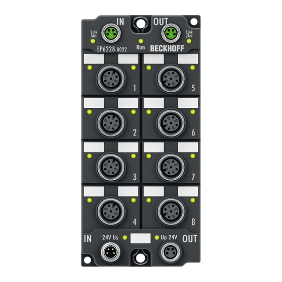
Page 21: Ep6228-0022
In the standard setting, the EP6228-0022 functions as a 8-channel input terminal, 24 V DC, which communicates with connected IO-Link devices, parameterises them and, if necessary, changes their operating mode. Quick links Technical data [} 29] Process image [} 22] Dimensions [} 57] Connections: IO-Link [} 67] Commissioning and configuration [} 73] EP6224 and EP6228 Version: 2.3... - Page 22 Process data of the IO-Link device at port 7 Module 10 Process data of the IO-Link device at port 8 The modules "Module 3" to "Module 6" only exist in the process data if the corresponding IO-Link ports have been configured. Version: 2.3 EP6224 and EP6228...
- Page 23 Module 7 State Ch6 Module 8 State Ch7 Module 9 State Ch8 Module 10 The modules "Module 3" to "Module 10" only exist in the process data if the corresponding IO-Link ports have been configured. EP6224 and EP6228 Version: 2.3...
- Page 24 Pre-assembled protective caps do not ensure IP67 protection Protective caps are pre-assembled at the factory to protect connectors during transport. They may not be tight enough to ensure IP67 protection. Ensure that the protective caps are correctly seated to ensure IP67 protection. Version: 2.3 EP6224 and EP6228...
-
Page 25: Ep6228-0042
In the standard setting, the EP6228-0042 functions as a 8-channel input terminal, 24 V DC, which communicates with connected IO-Link devices, parameterizes them and, if necessary, changes their operating mode. Quick links Technical data [} 29] Process image [} 26] Dimensions [} 59] Connections: IO-Link [} 67] Commissioning and configuration [} 73] EP6224 and EP6228 Version: 2.3... - Page 26 Module 10 Process data of the IO-Link device at port 8 Module 11 Digital inputs. The modules "Module 3" to "Module 10" only exist in the process data if the corresponding IO-Link ports have been configured. Version: 2.3 EP6224 and EP6228...
- Page 27 State Ch7 Pin 2 Ch7 Module 9 State Ch8 Pin 2 Ch8 Module 10 The modules "Module 3" to "Module 10" only exist in the process data if the corresponding IO-Link ports have been configured. EP6224 and EP6228 Version: 2.3...
- Page 28 Pre-assembled protective caps do not ensure IP67 protection Protective caps are pre-assembled at the factory to protect connectors during transport. They may not be tight enough to ensure IP67 protection. Ensure that the protective caps are correctly seated to ensure IP67 protection. Version: 2.3 EP6224 and EP6228...
-
Page 29: Technical Data
Product overview 3.2.6 Technical data All values are typical values over the entire temperature range, unless stated otherwise. EtherCAT EP6224-0002 EP6224-0042 EP6224-2022 EP6228-0022 EP6228-0042 Connection input M8 socket, M12 socket, M8 socket, M8 socket, M12 socket, 4-pin 4-pin 4-pin 4-pin... - Page 30 Signal voltage "1" +11 … +30 V +11 … +30 V - +11 … +30 V Input current 3 mA 3 mA 3 mA The digital inputs of EP6224-0002 and EP6228-0042 are located at pin 2 of the IO-Link ports. Housing data EP6224-0002 EP6224-0042 EP6224-2022 EP6228-0022 EP6228-0042 Dimensions without connector 30 mm x 60 mm x 60 mm x 60 mm x 60 mm x...
-
Page 31: Io-Link Master With Class B Ports
EtherCAT Box, 4-channel communication interface, IO-Link, master, Class B, M12 The EP6224-3002 IO-Link module enables the connection of up to four IO-Link devices. These can be actuators, sensors or a combination of both. An additional supply voltage is available on the Class B ports for IO-Link devices with higher power requirements. - Page 32 Product overview 3.3.1.2 Process image EP6224-3002 Module 1 Diagnosis. See chapter Further error diagnosis [} 114]. Module 2 Status variables of the IO-Link ports Module 3 Process data of the IO-Link device at port X01 Module 4 Process data of the IO-Link device at port X02...
- Page 33 Product overview 3.3.1.3 Scope of supply EP6224-3002 Make sure that the following components are included in the scope of delivery: • 1x EP6224-3002 • 2x protective cap for EtherCAT socket, M8, green (pre-assembled) • 1x protective cap for supply voltage input, M8, transparent (pre-assembled) •...
-
Page 34: Ep6224-3022
4-channel IO-Link master The EP6224-3022 IO-Link module enables connection of up to four IO-Link devices, e.g. actuators, sensors or combinations of both. A point-to-point connection is used between the box and the device. The terminal is parameterised via the EtherCAT master. IO-Link is designed as an intelligent link between the fieldbus level and the sensor, wherein parameterisation information can be exchanged bidirectionally via the IO-Link connection. - Page 35 Product overview 3.3.2.2 Process image EP6224-3022 Module 1 Diagnosis. See chapter Further error diagnosis [} 114]. Module 2 Status bytes of the IO-Link ports. See chapter Status of the IO-Link ports [} 109]. Module 3 Process data of the IO-Link device at port 1 Module 4 Process data of the IO-Link device at port 2...
- Page 36 Scope of supply EP6224-3022 Make sure that the following components are included in the scope of delivery: • 1x EP6224-3022 EtherCAT Box • 1x protective cap for supply voltage input, M8, transparent (pre-assembled) • 1x protective cap for supply voltage output, M8, black (pre-assembled) •...
-
Page 37: Ep6228-3032
The 7/8" power supply connectors offer an increased total current of the EtherCAT Box so that all IO-Link ports can be operated with maximum current. Quick links Technical data [} 41] Process image [} 38] Dimensions [} 58] Connections: IO-Link [} 67] Commissioning and configuration [} 73] EP6224 and EP6228 Version: 2.3... - Page 38 Process data of the IO-Link device at port 7 Module 10 Process data of the IO-Link device at port 8 The modules "Module 3" to "Module 10" only exist in the process data if the corresponding IO-Link ports have been configured. Version: 2.3 EP6224 and EP6228...
- Page 39 Module 7 State Ch6 Module 8 State Ch7 Module 9 State Ch8 Module 10 The modules "Module 3" to "Module 10" only exist in the process data if the corresponding IO-Link ports have been configured. EP6224 and EP6228 Version: 2.3...
- Page 40 Pre-assembled protective caps do not ensure IP67 protection Protective caps are pre-assembled at the factory to protect connectors during transport. They may not be tight enough to ensure IP67 protection. Ensure that the protective caps are correctly seated to ensure IP67 protection. Version: 2.3 EP6224 and EP6228...
-
Page 41: Technical Data
4.0 A in total, short-circuit proof proof C/Q input filter none C/Q output current max. 200 mA, not short-circuit proof Port pairs with common limitation of P24: • 1 + 5 • 2 + 6 • 3 + 7 • 4 + 8 EP6224 and EP6228 Version: 2.3... - Page 42 The devices have undergone the following additional tests: Test Explanation Vibration 10 frequency sweeps in 3 axes 5 Hz < f < 60 Hz displacement 0.35 mm, constant amplitude 60.1 Hz < f < 500 Hz acceleration 5 g, constant amplitude Shocks 1000 shocks in each direction, in 3 axes 35 g, 11 ms Version: 2.3 EP6224 and EP6228...
-
Page 43: Io-Link Master With Class A Ports And Class B Ports
In the standard setting, the EP6228-3132 functions as a 8-channel input terminal, 24 V DC, which communicates with connected IO-Link devices, parameterizes them and, if necessary, changes their operating mode. Quick links Technical data [} 51] Process image [} 44] Dimensions [} 58] Connections: IO-Link [} 68] Commissioning and configuration [} 73] EP6224 and EP6228 Version: 2.3... - Page 44 Process data of the IO-Link device at port 8 Module 11 Digital inputs of ports 1, 2, 5, 6 (Class A ports) The modules "Module 3" to "Module 10" only exist in the process data if the corresponding IO-Link ports have been configured. Version: 2.3 EP6224 and EP6228...
- Page 45 State Ch6 Pin 2 Ch6 Module 8 State Ch7 Module 9 State Ch8 Module 10 The modules "Module 3" to "Module 10" only exist in the process data if the corresponding IO-Link ports have been configured. EP6224 and EP6228 Version: 2.3...
- Page 46 Pre-assembled protective caps do not ensure IP67 protection Protective caps are pre-assembled at the factory to protect connectors during transport. They may not be tight enough to ensure IP67 protection. Ensure that the protective caps are correctly seated to ensure IP67 protection. Version: 2.3 EP6224 and EP6228...
-
Page 47: Ep6228-3142
In the standard setting, the EP6228-3142 functions as a 8-channel input terminal, 24 V DC, which communicates with connected IO-Link devices, parameterizes them and, if necessary, changes their operating mode. Quick links Technical data [} 51] Process image [} 48] Dimensions [} 59] Connections: IO-Link [} 68] Commissioning and configuration [} 73] EP6224 and EP6228 Version: 2.3... - Page 48 (Port Class B) Module 11 Digital inputs of ports 1, 2, 5, 6 (Class A ports) The modules "Module 3" to "Module 10" only exist in the process data if the corresponding IO-Link ports have been configured. Version: 2.3 EP6224 and EP6228...
- Page 49 State Ch6 Pin 2 Ch6 Module 8 State Ch7 Module 9 State Ch8 Module 10 The modules "Module 3" to "Module 10" only exist in the process data if the corresponding IO-Link ports have been configured. EP6224 and EP6228 Version: 2.3...
- Page 50 Pre-assembled protective caps do not ensure IP67 protection Protective caps are pre-assembled at the factory to protect connectors during transport. They may not be tight enough to ensure IP67 protection. Ensure that the protective caps are correctly seated to ensure IP67 protection. Version: 2.3 EP6224 and EP6228...
-
Page 51: Technical Data
4.0 A per port pair , short-circuit proof C/Q input filter none C/Q output current max. 200 mA, not short-circuit proof Port pairs with common limitation of P24: • Port 3 and 7 • Port 4 and 8 EP6224 and EP6228 Version: 2.3... - Page 52 The devices have undergone the following additional tests: Test Explanation Vibration 10 frequency sweeps in 3 axes 5 Hz < f < 60 Hz displacement 0.35 mm, constant amplitude 60.1 Hz < f < 500 Hz acceleration 5 g, constant amplitude Shocks 1000 shocks in each direction, in 3 axes 35 g, 11 ms Version: 2.3 EP6224 and EP6228...
-
Page 53: Io-Link Basics
The IO-Link master provides the interface to the higher-level controller and controls communication with the connected IO-Link devices. The IO-Link masters from Beckhoff have several IO-Link ports, to each of which one IO-Link device can be connected. IO-Link is not a fieldbus, but rather a point-to-point connection. -
Page 54: Establishment Of Io Link Communication
V1.0, this step is omitted and the device changes directly to OP. • Finally the cycle time is written and the device changes to OP. After that the master cyclically exchanges data with the device. Version: 2.3 EP6224 and EP6228... -
Page 55: Device Description Iodd
In order to be able to use the functionality of the parameter server, both the IO-Link master and the IO-Link device must be specified to V1.1. The IO-Link revision of the device can be read for the individual port under Settings [} 87]. All IO-Link masters from Beckhoff with current firmware support the IO-Link specification V1.1. -
Page 56: Mounting And Connections
Power feed through max. 4 A Installation position variable Protection class IP65, IP66, IP67 (conforms to EN 60529) when screwed together Dimensions (H x W x D) approx. 126 x 30 x 26.5 mm (without connectors) Version: 2.3 EP6224 and EP6228... -
Page 57: Ep622X-Xx22 Dimensions
Contacts CuZn, gold-plated Installation position variable Protection class IP65, IP66, IP67 (conforms to EN 60529) when screwed together Dimensions (H x W x D) approx. 126 x 60 x 26.5 mm (without connectors) EP6224 and EP6228 Version: 2.3... -
Page 58: Ep622X-Xx32 Dimensions
16 A at 40°C (according to IEC 60512-3) Installation position variable Protection class IP65, IP66, IP67 (conforms to EN 60529) when screwed together Dimensions (H x W x D) approx. 150 x 60 x 26.5 mm (without connectors) Version: 2.3 EP6224 and EP6228... -
Page 59: Ep622X-Xx42 Dimensions
16 A at 40°C (according to IEC 60512-3) Installation position variable Protection class IP65, IP66, IP67 (conforms to EN 60529) when screwed together Dimensions (H x W x D) approx. 150 x 60 x 26.5 mm (without connectors) EP6224 and EP6228 Version: 2.3... -
Page 60: Mounting
• Protect the plug connectors against dirt during the assembly. Mount the module with two M4 screws in the centrally located mounting holes. 5.1.6 Tightening torques for plug connectors Screw connectors tight with a torque wrench. (e.g. ZB8801 from Beckhoff) Connector diameter Tightening torque 0.4 Nm 0.6 Nm... -
Page 61: Connections
Connections Guidelines Follow these guidelines to ensure IP67 protection: • Mount connectors with the specified torque [} 60]. Use a torque wrench, e.g. Beckhoff ZB8801. • Seal unused connectors with protective caps. • Ensure the correct seating of pre-assembled protective caps. -
Page 62: Supply Voltages
In some types of EtherCAT Box modules the ground potentials GND and GND are connected. • If several EtherCAT Box modules are supplied with the same electrically isolated voltages, check whether there is an EtherCAT Box among them in which the ground potentials are connected. Version: 2.3 EP6224 and EP6228... - Page 63 White GND to U Blue GND to U Black Functional earth Grey The core colors apply to cables of the type: Beckhoff ZK2020-xxxx-xxxx 5.2.1.2 Status LEDs Fig. 6: Status LEDs for the supply voltages Display Meaning The supply voltage U is not available.
- Page 64 1.5 mm² 2.5 mm² 16 A Vert. Faktor: 0,45 cm / V Vert. Faktor: 0,4 12 A 16 A Vert. Faktor: 0,45 cm / V Vert. Faktor: 12 A Cable length (m) Cable length (m) Version: 2.3 EP6224 and EP6228...
-
Page 65: Ethercat
Assimilation of color coding for cable ZB9030, ZB9032 and ZK1090-3xxxx-xxxx (with M8 connectors) For unification, the prevalent cables ZB9030, ZB9032 and ZK1090-3xxx-xxxx were changed to the colors of EN61918 (yellow, orange, white, blue). So different color coding exists. But the electrical properties are absolutely identical. EP6224 and EP6228 Version: 2.3... - Page 66 (CAT5) according to EN 50173 or ISO/IEC 11801 should be used. EtherCAT uses four wires for signal transmission. Thanks to automatic line detection ("Auto MDI-X"), both symmetrical (1:1) or cross-over cables can be used between Beckhoff EtherCAT. Detailed recommendations for the cabling of EtherCAT devices Version: 2.3 EP6224 and EP6228...
-
Page 67: Io-Link
Wire color Sensor/logic supply (from U brown Actuator supply (from U white GND to L+ blue IO-Link data cable black GND to P24 gray The core colors apply to M12 cables from Beckhoff: ZK2000-5xxx, ZK2000-6xxx, ZK2000-7xxx EP6224 and EP6228 Version: 2.3... - Page 68 Sensor/logic supply (U brown Digital input Actuator supply (U white GND to L+ blue IO-Link data IO-Link data black GND to P24 grey The core colors apply to M12 cables from Beckhoff: ZK2000-5xxx, ZK2000-6xxx, ZK2000-7xxx Version: 2.3 EP6224 and EP6228...
- Page 69 Logic level high Port configured as digital input or output 2 - Digital input DI (EP6228-0042, EP6228-3132, EP6228-3142) The LED lights up when a high level is present on the digital input DI. EP6224 and EP6228 Version: 2.3...
- Page 70 Wire color brown Input B white blue Input A black Functional earth FE gray The wire colors apply to M12 cables from Beckhoff. See chapter Accessories [} 126]. Connection examples Input B Pin 2 GNDs Pin 3 Pin 1 GNDs Pin 3...
-
Page 71: Ul Requirements
To meet the UL requirements, EtherCAT Box Modules has to be operated only at an ambient temperature range of -25 °C to +55 °C! Marking for UL All EtherCAT Box Modules certified by UL (Underwriters Laboratories) are marked with the following label. Fig. 11: UL label EP6224 and EP6228 Version: 2.3... -
Page 72: Disposal
Products marked with a crossed-out wheeled bin shall not be discarded with the normal waste stream. The device is considered as waste electrical and electronic equipment. The national regulations for the disposal of waste electrical and electronic equipment must be observed. Version: 2.3 EP6224 and EP6228... -
Page 73: Commissioning And Configuration
Commissioning and configuration Commissioning and configuration Integrating into a TwinCAT project The procedure for integration in a TwinCAT project is described in these Quick start guide. EP6224 and EP6228 Version: 2.3... -
Page 74: Configuration Of The Io Link Master
EtherCAT XML device description and configuration files The display matches that of the CoE objects from the EtherCAT XML Device Description. We recommend downloading the latest XML file from the download area of the Beckhoff website and installing it according to installation instructions. -
Page 75: Configuration Of The Io-Link Devices
The device catalog contains an alphabetically sorted list of the IO-Link devices for which a device description (IODD) exists in the local TwinCAT installation. The IODDs for the EPIxxxx, ERIxxxx IO-Link Box modules from Beckhoff can be downloaded via the Download finder. The downloaded zip file contains the IODD device description files for the Beckhoff EPIxxxx, ERIxxxx IO-Link Box modules. -
Page 76: Integrating Io-Link Devices
• Manual integration of the IO-Link devices via “Create Device” should only be carried out if the IODD of the vendor and the IO-Link device are not available at the time of project creation. Fig. 14: Creating IO-Link devices Version: 2.3 EP6224 and EP6228... - Page 77 2. Searching for the desired IO-Link sensor/device by entering them in the search mask; see the figure below (1) 3. Selecting the desired IO-Link sensor/device. Move the mouse pointer over the figure of the desired IO- Link sensor/device. A blue download icon appears, see the following figure (2). EP6224 and EP6228 Version: 2.3...
- Page 78 (3)) that the .xml file already exists. Fig. 17: IODD Finder, display of an already imported device description ð The imported device descriptions are listed in a tree structure in the “Catalog” field of the IO-Link tab, sorted by vendor. Version: 2.3 EP6224 and EP6228...
- Page 79 Example of port assignment on the IO link master EL6224 Port1: Port2: Port3: EPI3174-0002 is assigned is configured as digital input EPI1008-0001 will be assigned Process data of Port1 and Port2 are displayed in the Solution Explorer. EP6224 and EP6228 Version: 2.3...
- Page 80 Only port2 of the master is assigned an IO-Link device. ð Confirm with the OK button. Fig. 19: Information “Scan devices” 1. To be able to work with the devices, the button “Reload Devices” must be clicked. Version: 2.3 EP6224 and EP6228...
- Page 81 The IO-Link devices are now entered in the General display. The Port2 “Details” field displays information about the connected device. Additionally the tabs Settings [} 82] and Parameter [} 83] can be opened. Fig. 20: Device at Port2, Display “Details”, open tabs “Settings” and “Parameter” EP6224 and EP6228 Version: 2.3...
- Page 82 1. Right-click on port2, to display more details in dialog “Settings”. 2. If necessary, change the settings as described in chapter Settings of the IO-Link devices [} 87]. Fig. 21: Settings of the device assigned to port2 Version: 2.3 EP6224 and EP6228...
- Page 83 ð The Parameters of of the respective IO link device are listed. 2. Parameterize the device as described in chapter EPIxxxx, ERIxxxx - Setting of the IO-Link device parameters [} 89]. Fig. 22: Parameter of the device assigned to port2 EP6224 and EP6228 Version: 2.3...
- Page 84 Even when manually creating and scanning, the IODD should always be read in as well in order to display further sensor-specific information. 7. In the “Settings” tab of the IO link devices further settings can be made as described in chapter Settings of the IO-Link devices [} 87]. Version: 2.3 EP6224 and EP6228...
-
Page 85: Removal Of Io-Link Devices
2. Activate the IO link configuration [} 86], so that changes become effective. ð The already create process data are removed. Fig. 25: The device was removed from the port2, the process data no longer displayed in the tree. EP6224 and EP6228 Version: 2.3... -
Page 86: Activating The Configuration
Changes in the IO-Link configuration tool only become effective when you activate the IO-Link configuration. There are two ways to activate the IO-Link configuration: • Click on the "Reload Devices" button • Activate the TwinCAT configuration: Click on the "Activate Configuration" button Version: 2.3 EP6224 and EP6228... -
Page 87: Settings Of The Io-Link Devices
1. right-click on the port to open the context menu and select “Settings”. ð A new tab “Portx:: Settings” opens where the settings described below can be made. Fig. 26: Context menu - Settings Fig. 27: Settings of the IO-Link devices EP6224 and EP6228 Version: 2.3... - Page 88 ð complex data types (process data) are created as octet strings. Advantage: simple further processing in the 9. Firmware Update of the Beckhoff IO-Link devices For a firmware update use the “Download” button. Observe the description in the documentation of EPIxxxx boxes in chapter Firmware Update des IO-Link Devices.
-
Page 89: Epixxxx, Erixxxx - Setting Of The Io-Link Device Parameters
Restarting the IO link device or restoring of the application parameters is possible via the parameter Standard Command [} 98]. Application specific information can be specified in parameter (0x0018) Application Specific Tag [} 99]. EP6224 and EP6228 Version: 2.3... - Page 90 Deviations are indicated by a pen-symbol in front of the index. If there are different values in the “Value” field, the value “Compare” is displayed (see Index 0x0018 “Application Specific Tag”). Fig. 29: Display of deviating data in the “Parameter” tab Version: 2.3 EP6224 and EP6228...
- Page 91 Commissioning and configuration Fig. 30: Compare configuration and sensor data EP6224 and EP6228 Version: 2.3...
- Page 92 ð The data is written to the device (offline configuration is possible). The successful writing process is confirmed via a storing symbol in front of the index. Fig. 31: Write parameter data to the sensor, read parameter data from the sensor. Version: 2.3 EP6224 and EP6228...
- Page 93 ð All parameter values are set to the default settings. Write default-values to the sensor Note that the default-values must also be written to the device via the “Write” button. Fig. 32: Reset parameter values to default EP6224 and EP6228 Version: 2.3...
- Page 94 ð The data is written to the device (offline configuration is possible). The successful writing process is confirmed via a storing symbol in front of the index. Fig. 33: Parameterization IO-Link device - Export / Import Version: 2.3 EP6224 and EP6228...
- Page 95 Commissioning and configuration “Store” button 1. Click “Store” (data storage): ð The Beckhoff IO-Link master stores sensor-dependent-data, e. g. the following parameters (0x0018) “Application-Specific Tag”, (0x08n0) “Settings” and 0x3800 “Range Settings”. The success of storing process is marked with the storing symbol.
- Page 96 Use an ADS Write function block for activating the store-function via the plc. The following figure shows a sample code for activation of the store-Button (command 0x05 “ParamDownloadStore”) Fig. 36: Sample code for activation of the store-function via the plc Version: 2.3 EP6224 and EP6228...
- Page 97 Commissioning and configuration Fig. 37: Store parameters EP6224 and EP6228 Version: 2.3...
- Page 98 3. Use the “Write” button (as described above [} 92]). ð The data is written to the device (offline configuration is possible). The successful writing process is confirmed via a storing symbol in front of the index. Fig. 38: Parameters IO-Link device “Standard Command” Version: 2.3 EP6224 and EP6228...
- Page 99 2. Enter application-specific information and confirm with the Enter key. 3. Use the Write [} 92] button and the Store [} 95] button, if required (as described above). Fig. 39: Parameters IO-Link device: “Application Specific Tag” EP6224 and EP6228 Version: 2.3...
-
Page 100: Access To Io-Link Data
AoE [} 102]. The events are additionally displayed under Diag History [} 105] in the System Manager. • Cyclic data: - Process data - Value status • Acyclic data: - Device data - Events Version: 2.3 EP6224 and EP6228... -
Page 101: Pdo Assignment
Port (n-1) Process Data) are only displayed after configuring on the respective port and restarting the EtherCAT system or reloading the configuration in Config mode (F4); see Configuration of the IO-Link master. Fig. 41: Illustration of the EP6224-2022 process data allocation, SM3 inputs SM3, PDO Assignment 0x1C13 Index Size (byte.bit) -
Page 102: Accessing Io-Link Parameters
0xB_ = error PreOP/Data storage (error in IO-Link State PreOP) 6.6.3 Accessing IO-Link parameters The exchange of the acyclic data takes place via a specified index and subindex range that is device-specific and can be read about in the corresponding vendor documentation. Version: 2.3 EP6224 and EP6228... -
Page 103: Parameter Data Exchange
• INITMASTER: Readout the IO-Link device and check the communication parameters • INITDEVICE: Initialization of the IO-Link device • PREOPERATE: Parameter server is running • OPERATE: The port is used for IO-Link communication • STOP: Communication is stopped (COM-stop) EP6224 and EP6228 Version: 2.3... -
Page 104: Ads
0x1000. I.e. IO-Link Port1 corresponds to PortNo 0x1000 and IO-Link Portn corresponds to PortNo 0x1000 + n-1. The following specification applies for the EP6224 (4-port IO-Link master): • IO-Link Port1 corresponds to PortNo 0x1000 • IO-Link Port2 corresponds to PortNo 0x1001 •... -
Page 105: Access To Events
0. • Export Diag History: the events that have occurred can be exported as a "txt" file and thus archived. • Advanced: this field currently (as at 3 quarter 2015) has no function. EP6224 and EP6228 Version: 2.3... -
Page 106: Plc Library: Tc3_Iolink
Function blocks are available for this purpose that support the "Common Profile" and "Smart Sensor Profile" and enable parameters to be read and written. See software documentation in the Beckhoff Information System: TwinCAT 3 | PLC Library: Tc3_IoLink Version: 2.3... -
Page 107: Restoring The Delivery State
Alternative restore value In some older terminals / boxes the backup objects can be switched with an alternative restore value: Decimal value: 1819238756 Hexadecimal value: 0x6C6F6164 An incorrect entry for the restore value has no effect. EP6224 and EP6228 Version: 2.3... -
Page 108: Decommissioning
Commissioning and configuration Decommissioning WARNING Risk of electric shock! Bring the bus system into a safe, de-energized state before starting disassembly of the devices! Version: 2.3 EP6224 and EP6228... -
Page 109: Diagnosis
Status of the IO-Link ports There is a status byte for each IO-Link port. You can find the status bytes at the following locations: • In the process data object "Module 2 (DeviceState Inputs)" (example for EP6224-0002) • In the CoE object F100 [} 124] 7.1.1 Interpretation of the status bytes The status bytes are divided into two nibbles. - Page 110 If diagnosis messages occur simultaneously, the value is output as a sum in the status byte of the relevant channel. • Often 0x03 "Port in communication OP" and 0x08 "Process Data Invalid Bit" occur simultaneously: 0x03 + 0x08 = 0x0B (11 ð The value 0x0B (11 ) is output in the status byte. Version: 2.3 EP6224 and EP6228...
-
Page 111: Ads Error Codes
The possible error codes are listed in tables C.1 and C.2. Example of an AdsReturnCode AdsReturnCode 0x80110700 - 80: Device Application Error (IO-Link Spec), - 11: Index not Available (IO-Link Spec), - 0700: General ADS Error EP6224 and EP6228 Version: 2.3... - Page 112 Vendor specific 0x81 0x00 UNSPECIFIC This ErrorType will be propagated directly to higher level processing elements as an error (no warning) by the Vendor specific 0x81 0x01 to VENDOR_SPECIFIC Master. 0xFF Table C.1 ErrorTypes, IO-Link Spec Version: 2.3 EP6224 and EP6228...
- Page 113 Error, single shot, returned to the requester (see parameter length overrun) 0x5200) Events from legacy Devices shall be redirected in compatibility mode to this derived ErrorType Table C.2 Derived ErrorTypes, IO-Link Spec EP6224 and EP6228 Version: 2.3...
-
Page 114: Further Error Diagnosis
In case of error these objects can be used to compare the configuration with the actual state. Lost Frame Counter The Lost Frame counter in object 0xA0n0:02 is for the diagnosis of the transmission quality. TwinCAT provides the possibility here to diagnose problems, e. g. with the wiring, EMC or power supply. Version: 2.3 EP6224 and EP6228... -
Page 115: Coe Parameters
EtherCAT XML Device Description The display matches that of the CoE objects from the EtherCAT XML Device Description. We recommend downloading the latest XML file from the download area of the Beckhoff website and installing it according to installation instructions. - Page 116 (indicates whether the value in LENGTH interpreted as bit length [bit not set] or as byte length + 1 [bit set] Bit 6: (indicates whether the device supports the standard IO mode [bit set]) Bit 0 to 4: LENGTH (length of the process data) Version: 2.3 EP6224 and EP6228...
-
Page 117: Objects For Regular Operation
Data type Flags Default 1009:0 Hardware version Hardware version of the EtherCAT slaves STRING Index 100A Software version Index (hex) Name Meaning Data type Flags Default 100A:0 Software version Firmware version of the EtherCAT slaves STRING EP6224 and EP6228 Version: 2.3... - Page 118 Index 1A00 IO TxPDOPDO-Map Ch.1 Index (hex) Name Meaning Data type Flags Default 1A00:0 IO TxPDOPDO-Map PDO Mapping TxPDO 1 UINT8 0x01 (1 Ch.1 1A00:01 SubIndex 001 1. PDO Mapping entry (8 bits align) UINT32 0x0000:00, 8 Version: 2.3 EP6224 and EP6228...
- Page 119 SubIndex 003 3. assigned RxPDO (contains the index of the UINT16 0x1602 corresponding RxPDO Mapping object) (5634 1C12:04 SubIndex 004 4. assigned RxPDO (contains the index of the UINT16 0x1603 corresponding RxPDO Mapping object) (5635 EP6224 and EP6228 Version: 2.3...
- Page 120 Shift too short counter Number of the too short distances between SYNC0 UINT16 0x0000 (0 and SYNC1 Event (only in DC Mode) 1C32:20 Sync error TRUE: In the last cycle the synchronization was not BOOLEAN 0x00 (0 correct (only in DC Mode) Version: 2.3 EP6224 and EP6228...
- Page 121 1C32:11 UINT16 0x0000 (0 counter 1C33:0C Cycle exceeded same as 1C32:12 UINT16 0x0000 (0 counter 1C33:0D Shift too short counter same as 1C32:13 UINT16 0x0000 (0 1C33:20 Sync error same as 1C32:32 BOOLEAN 0x00 (0 EP6224 and EP6228 Version: 2.3...
-
Page 122: Profile Specific Objects (0X6000-0Xffff)
Index 70n0 IO Outputs Ch.1 - 4 (for 0 ≤ n ≤ 3) Index (hex) Name Meaning Data type Flags Default 70n0:0 IO Outputs Ch.1 - 4 Max. Subindex UINT8 0x00 (0 70n0:01 Subindex 001 IO-Link output process data 70n0:10 Subindex 016 IO-Link output process data Version: 2.3 EP6224 and EP6228... - Page 123 Bit 6: (indicates whether the device supports the standard IO mode [bit set]) Bit 0 bis 4: LENGTH (length of the process data) 90n0:26 Reserved reserved UINT16 0x0000 (0 90n0:27 Reserved2 reserved UINT16 0x0000 (0 EP6224 and EP6228 Version: 2.3...
- Page 124 F100:04 State Ch4 Status byte Ch. 4 UINT8 0x00 (0 Index F900 Info data Index (hex) Name Meaning Data type Flags Default F900:0 Info data Max. Subindex UINT8 0x09 (9 F900:01 IO-Link Version UINT8 0x10 (16 Version: 2.3 EP6224 and EP6228...
-
Page 125: Appendix
(ph-Value > 12) > 40°C: not resistant Acetic acid not resistant Argon (technical clean) resistant • resistant: Lifetime several months • non inherently resistant: Lifetime several weeks • not resistant: Lifetime several hours resp. early decomposition EP6224 and EP6228 Version: 2.3... -
Page 126: Accessories
Torque cable key for M12 / wrench size 13 for ZB8801-0000 ZB8801-0003 Torque cable key for M12 field assembly / wrench size 18 for ZB8801-0000 Further accessories Further accessories can be found in the price list for fieldbus components from Beckhoff and online at https://www.beckhoff.com. Version: 2.3 EP6224 and EP6228... -
Page 127: Version Identification Of Ethercat Devices
Associated and synonymous with each revision there is usually a description (ESI, EtherCAT Slave Information) in the form of an XML file, which is available for download from the Beckhoff web site. From 2014/01 the revision is shown on the outside of the IP20 terminals, see Fig. “EL5021 EL terminal, standard IP20 IO device with batch number and revision ID (since 2014/01)”. -
Page 128: Version Identification Of Ip67 Modules
Version identification of IP67 modules The serial number/ data code for Beckhoff IO devices is usually the 8-digit number printed on the device or on a sticker. The serial number indicates the configuration in delivery state and therefore refers to a whole production batch, without distinguishing the individual modules of a batch. -
Page 129: Beckhoff Identification Code (Bic)
9.3.3 Beckhoff Identification Code (BIC) The Beckhoff Identification Code (BIC) is increasingly being applied to Beckhoff products to uniquely identify the product. The BIC is represented as a Data Matrix Code (DMC, code scheme ECC200), the content is based on the ANSI standard MH10.8.2-2016. - Page 130 Fig. 48: Example DMC 1P072222SBTNk4p562d71KEL1809 Q1 51S678294 An important component of the BIC is the Beckhoff Traceability Number (BTN, position 2). The BTN is a unique serial number consisting of eight characters that will replace all other serial number systems at Beckhoff in the long term (e.g.
-
Page 131: Electronic Access To The Bic (Ebic)
Electronic access to the BIC (eBIC) Electronic BIC (eBIC) The Beckhoff Identification Code (BIC) is applied to the outside of Beckhoff products in a visible place. If possible, it should also be electronically readable. Decisive for the electronic readout is the interface via which the product can be electronically addressed. - Page 132 EtherCAT, the eBIC of the top-level device is located in the CoE object directory 0x10E2:01 and the eBICs of the sub-devices follow in 0x10E2:nn. Profibus/Profinet/DeviceNet… Devices Currently, no electronic storage and readout is planned for these devices. Version: 2.3 EP6224 and EP6228...
-
Page 133: Support And Service
Please contact your Beckhoff branch office or representative for local support and service on Beckhoff products! The addresses of Beckhoff's branch offices and representatives round the world can be found on her internet pages: www.beckhoff.com You will also find further documentation for Beckhoff components there. - Page 135 Beckhoff Automation GmbH & Co. KG Hülshorstweg 20 33415 Verl Germany Phone: +49 5246 9630 info@beckhoff.com www.beckhoff.com...
Need help?
Do you have a question about the EP6224 and is the answer not in the manual?
Questions and answers