Table of Contents
Advertisement
Advertisement
Chapters
Table of Contents

Related Manuals for Beckhoff CX20 0 Series


Summary of Contents for Beckhoff CX20 0 Series
- Page 1 Manual | EN CX20x0 Embedded PC 11/10/2021 | Version: 2.5...
-
Page 3: Table Of Contents
Table of contents Table of contents 1 Notes on the documentation ........................ 7 Representation and structure of warnings .................. 8 Related documents.......................... 9 Documentation issue status ...................... 9 2 For your safety............................ 10 Intended use ............................ 10 Staff qualification .......................... 10 Safety instructions ........................... 11 Notes on information security ...................... 11 3 Transport and storage.......................... 13 4 Product overview............................. 14 Configuration of the basic CPU module .................. 16... - Page 4 7.2.2 Enabling jumbo frames .................... 47 7.2.3 Set NIC Teaming ...................... 48 7.2.4 Restoring the Beckhoff real-time driver................ 50 Windows 10 IoT Enterprise LTSB .................... 51 7.3.1 Identification of the Ethernet interfaces (X000, X001) ............. 51 Beckhoff Device Manager ....................... 52 7.4.1...
- Page 5 Table of contents List of tables............................. 88 List of figures ............................ 90 CX20x0 Version: 2.5...
- Page 6 Table of contents Version: 2.5 CX20x0...
-
Page 7: Notes On The Documentation
EP1590927, EP1789857, EP1456722, EP2137893, DE102015105702 with corresponding applications or registrations in various other countries. ® EtherCAT is a registered trademark and patented technology, licensed by Beckhoff Automation GmbH, Germany Copyright © Beckhoff Automation GmbH & Co. KG, Germany. The reproduction, distribution and utilization of this document as well as the communication of its contents to others without express authorization are prohibited. -
Page 8: Representation And Structure Of Warnings
Notes on the documentation Representation and structure of warnings The following warnings are used in the documentation. Read and follow the warnings. Warnings relating to personal injury: DANGER Hazard with high risk of death or serious injury. WARNING Hazard with medium risk of death or serious injury. CAUTION There is a low-risk hazard that can result in minor injury. -
Page 9: Related Documents
Further information on the devices of the CX2000 Embedded PC series can be found in the associated documentation. Read and follow in particular the sections on safety in this documentation. The following important documentation can be viewed at and downloaded from the Beckhoff website: http://www.beckhoff.de... -
Page 10: For Your Safety
Beckhoff Automation GmbH & Co. In addition, the following actions are excluded from the liability of Beckhoff Automation GmbH & Co. KG: • Failure to comply with this documentation. -
Page 11: Safety Instructions
IPC Security Guideline Notes on information security The products of Beckhoff Automation GmbH & Co. KG (Beckhoff), insofar as they can be accessed online, are equipped with security functions that support the secure operation of plants, systems, machines and networks. Despite the security functions, the creation, implementation and constant updating of a holistic security concept for the operation are necessary to protect the respective plant, system, machine and networks against cyber threats. - Page 12 Using outdated or unsupported product versions can increase the risk of cyber threats. To stay informed about information security for Beckhoff products, subscribe to the RSS feed at https:// www.beckhoff.com/secinfo.
-
Page 13: Transport And Storage
Transport and storage Transport and storage Transport NOTE Short circuit due to moisture Moisture can form during transport in cold weather or in the event of large temperature fluctuations. Avoid moisture formation (condensation) in the Embedded PC, and leave it to adjust to room temperature slowly. -
Page 14: Product Overview
Product overview Product overview The CX2000 product family consists of individual modules, which can be assembled to form a customized Embedded PC. The CX2000 product family consists of: • basic CPU modules, • CX2100 power supply units, • system, fieldbus and extension modules, •... -
Page 15: Table 2 Available Optional Interfaces For The Cx20X0
Product overview Table 2: Available optional interfaces for the CX20x0. CX20x0-xxxx Optional interfaces CX20x0-N010 DVI-D, additional DVI-D socket for clone and extended display mode. CX20x0-N011 DisplayPort, additional DisplayPort for clone and extended display mode CX20x0-N030 RS232, D-sub connector, 9-pin. CX20x0-N031 RS422/RS485, D-sub socket, 9-pin. CX20x0-B110 EtherCAT slave, EtherCAT IN and OUT (2 x RJ45). -
Page 16: Configuration Of The Basic Cpu Module
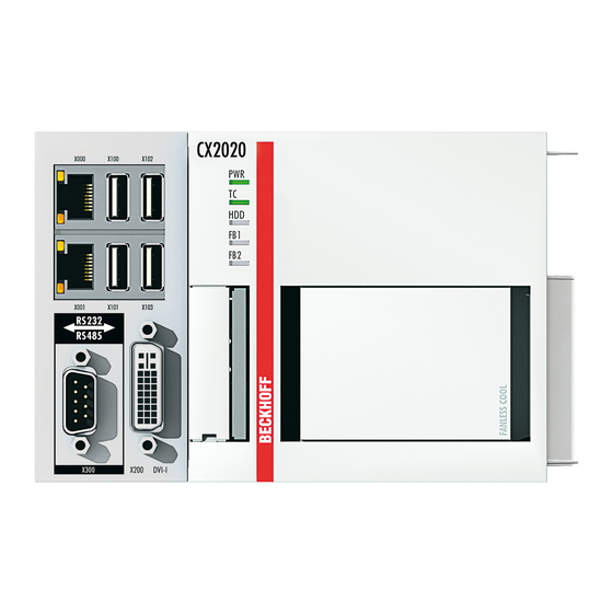
Product overview Configuration of the basic CPU module Fig. 2: Example: Embedded PCs CX2040 with active cooling. Table 3: Legend for the configuration of the basic CPU module Component Description Multi-pin connection (left) Extension through system modules and fieldbus modules of type CX2500. -
Page 17: Name Plate
Embedded PC, operating system, options and TwinCAT can be reordered. Product designation for identification of the Embedded PC Serial number/ Beckhoff Traceability Number (BTN) for the unambiguous identification of the product. Hardware version and date of manufacture. -
Page 18: Table 5 Cx20X0, Ordering Information For Software
Product overview Fig. 4: Nomenclature for the basic CPU module. The basic CPU module CX2020, CX2030 and CX2040 is available with the following software options: Table 5: CX20x0, ordering information for software. Module Windows Windows Windows Windows Windows Twin- Twin- Twin- Twin- operat- Embedded Embedded... -
Page 19: Architekture Overview
Product overview Architekture overview The Embedded PCs of the CX20x0 family all have the same architecture. The architecture is described below. Fig. 5: CX20x0 architecture overview. The CX20x0 Embedded PCs are based on the Sandy Bridge microarchitecture developed by Intel. The following CPUs are used: ®... - Page 20 Product overview • 1 PCIe lane for each of the two Intel® 82574L Gigabit Ethernet controllers • LPC interface for super I/O controller for serial interface (CX20x0-N03x). • 4 PCIe lanes via the multi-pin connection (left). • 1 PCIe to FPGA for K-/E-bus and NOVRAM. •...
-
Page 21: Interface Description
Interface description Interface description USB (X100, X101, X102, X103) The Embedded PC has four independent USB interfaces for connecting keyboards, mice, touchscreens and other input or data storage devices. Fig. 6: USB interfaces (X100, X101, X102, X103). The USB interfaces are type A and comply with the USB 2.0 specification. Table 6: USB interfaces (X100, X101, X102, X103), pin assignment. -
Page 22: Ethernet Rj45 (X000, X001)
Interface description Ethernet RJ45 (X000, X001) The two Ethernet interfaces are independent; no switch is integrated. The independent Ethernet interfaces can be configured in different ways. In the delivery state, the Ethernet interfaces (X000, X001) are configured for EtherCAT communication. Note that an additional switch is required for a line topology. -
Page 23: Dvi-I (X200)
The DVI-I interface (X200) transfers digital data and is suitable for connection to digital or analog monitors. The resolution at the display or the Beckhoff Control Panel depends on the distance from the display device. The maximum distance is 5 m. Beckhoff offers various Panels with an integrated “DVI extension”. These make a cable length of up to 50 meters possible. -
Page 24: Optional Interfaces
The DVI-D interface (X300) transfers digital data and is suitable for connection to digital displays. The resolution at the display or the Beckhoff Control Panel depends on the distance from the display device. The maximum distance is 5 m. Beckhoff offers various Panels with an integrated “DVI extension”. These make a cable length of up to 50 meters possible. -
Page 25: Displayport (N011)
Interface description 5.4.2 DisplayPort (N011) The DisplayPort transfers image and audio signal at the same time and is therefore suitable for connecting panels or monitors to the Embedded PC. Fig. 10: DisplayPort X300. Version 1.1a of the DisplayPort (DisplayPort++) is installed on the Embedded PC. Adapters from DisplayPort to DVI-D or DisplayPort to HDMI can be used to connect monitors without DisplayPort to the Embedded PC. -
Page 26: Rs232 (N030)
Interface description 5.4.3 RS232 (N030) The optional N030 interface provides an RS232 interface (X300). The RS232 interface is implemented on a 9-pin D-sub connector. Fig. 11: RS232 interface X300. The maximum baud rate on both channels is 115 kbit. The interface parameters are set via the operating system or from the PLC program. -
Page 27: Rs422/Rs485 (N031)
Interface description 5.4.4 RS422/RS485 (N031) The optional N031 interface provides an RS422 or RS485 interface (X300). The interface is executed on a 9- pin D-sub socket. Fig. 12: RS485 interface X300. The maximum baud rate on both channels is 115 kbit. The interface parameters are set via the operating system or from the PLC program. -
Page 28: Ethercat Slave (B110)
Receive + connected reserved RD - Receive - connected reserved For the optional EtherCAT slave interface (B110), documentation with further information is available for download from the Beckhoff website: https://www.beckhoff.de/german/download/epc.htm?id=71003127100362 Document name CXxxx0-B110 optional interface EtherCAT slave. Version: 2.5 CX20x0... -
Page 29: Profibus (X310)
PROFIBUS line D sub B red Pin 3 A green Pin 8 For the optional PROFIBUS interface (x310), documentation with further information is available for download from the Beckhoff website: https://www.beckhoff.de/german/download/epc.htm?id=71003127100362 Document name CXxxx0-x310 optional Profibus interface. CX20x0 Version: 2.5... -
Page 30: Canopen (X510)
CAN Ground (internally connected to pin 3) CAN high (CAN+) not used not used For the optional CANopen interface (x510), documentation with further information is available for download from the Beckhoff website: https://www.beckhoff.de/german/download/epc.htm?id=71003127100362 Document name CXxxx0-x510 optional CANopen interface. Version: 2.5... -
Page 31: Profinet Rt (X930)
Interface description 5.4.8 PROFINET RT (x930) Fig. 16: PROFINET RT interface X300. Table 22: PROFINET RT interface, pin assignment. Signal Description TD + Transmit + TD - Transmit - RD + Receive + connected reserved RD - Receive - connected reserved CX20x0 Version: 2.5... -
Page 32: Commissioning
Commissioning Commissioning Selecting the appropriate CX2100 power supply unit The basic CPU module requires a power supply unit of type CX2100-0xxx. Connect the power supply unit to the multi-pin port on the right of the basic CPU module. In horizontal installation position, any CX2100-0xxx power supply unit can be used. Table 23: Power supply units for horizontal installation position. -
Page 33: Table 25 Legend For Configuration Of The Power Supply Terminal
Commissioning Table 25: Legend for configuration of the power supply terminal. Description Description Diagnostic LEDs 0 V, Bus Terminal supply Terminal bus (K-bus or E-bus) Terminal release +24 V and 0 V, for basic CPU module PE, spring-loaded terminal +24 V, Bus Terminal supply +24 V, 0 V, PE, for power contacts CX20x0 Version: 2.5... -
Page 34: Mounting
Commissioning Mounting Fig. 18: CX2020 and CX2030 Embedded PC, dimensions. Fig. 19: CX2040 Embedded PC, dimensions. Version: 2.5 CX20x0... -
Page 35: Attaching The Power Supply Unit
Commissioning 6.2.1 Attaching the power supply unit The basic CPU module requires a power supply unit of type CX2100-0xxx. Connect the power supply unit to the multi-pin port on the right of the basic CPU module. Proceed as follows: 1. Select the appropriate power supply unit, as described in chapter Selecting the appropriate CX2100 power supply unit [} 32]. -
Page 36: Note The Permissible Installation Positions
Commissioning 6.2.3 Note the permissible installation positions NOTE Overheating The Embedded PC may overheat if the installation position is incorrect or the minimum distances are not adhered to. Adhere to the maximum ambient temperature of 60°C and the mounting instructions. Install the Embedded PC horizontally in the control cabinet on a mounting rail, in order to ensure optimum heat dissipation. - Page 37 Commissioning If vibrations and impact occur in the same direction as the mounting rail, the Embedded PC must be secured with an additional bracket, in order to prevent it slipping. Permitted installation positions with fan Only Embedded PCs with an active cooling can be installed vertically or horizontally on the mounting rail. Without active cooling the Embedded PC is not ventilated adequately in vertical or horizontal position.
-
Page 38: Attaching On Mounting Rail
Commissioning 6.2.4 Attaching on mounting rail The housing is designed such that the Embedded PC can be pushed against the mounting rail and latched onto it. Requirements: • Mounting rail of type TS35/7.5 or TS35/15 according to DIN EN 60715. Secure the Embedded PC on the mounting rail as follows: 1. -
Page 39: Cfast Card Installation And Removal
A CFast card is a non-volatile memory. Data to be retained in the event of a power failure should be saved on the CFast card. The CFast cards supplied by Beckhoff are industrial cards with an increased number of write cycles and an extended temperature range (+85 °C). -
Page 40: Installing Passive Ethercat Terminals
Commissioning 6.2.6 Installing passive EtherCAT Terminals Incorrectly installed passive EtherCAT Terminals The E-bus signal between an Embedded PC and the EtherCAT Terminals can be impaired due to incorrectly installed passive EtherCAT Terminals. Passive EtherCAT Terminals should not be installed directly on the power supply unit. EtherCAT Terminals that do not take part in active data exchange are referred to as passive terminals. -
Page 41: Power Supply
Commissioning Power supply NOTE Damage to the Embedded PCs The Embedded PCs may be damaged during wiring. The cables for the power supply should only be con- nected in de-energized state. The power supply units require an external voltage source, which provides 24 V DC (-15% / +20%). The cabling of the Embedded PC in the control cabinet must be done in accordance with the standard EN 60204-1:2006 (PELV = Protective Extra Low Voltage): •... -
Page 42: Connect Embedded Pc
Commissioning 6.3.1 Connect Embedded PC The cables of an external voltage source are connected to the power supply unit with spring-loaded terminals. Observe the required conductor cross-sections and strip lengths. Table 28: Required conductor cross-sections and strip lengths. Conductor cross-section 0.5 ... 2.5 mm AWG 20 ... -
Page 43: Switching On
Commissioning Fig. 25: UL label for CX20x0. The Embedded PCs CX20x0 can thus be used in areas in which special UL requirements have to be met. These requirements apply to the system voltage (Us) and the power contacts (Up). Applications without special UL requirements are not affected by UL regulations. -
Page 44: Switching Off
Commissioning Switching off NOTE Loss of data If the Embedded PC is switched off during operation, data on the CFast card or other hard disks may be lost. Do not disconnect the Embedded PC from the power supply during operation. Switch off the Embedded PC as follows: 1. -
Page 45: Configuration
Configuration Configuration Windows Embedded Compact 7 7.1.1 Scan for new hardware Under Windows Embedded Compact 7 the Embedded PC scans for new hardware on the PCI bus the first time it is started. After that the hardware is permanently registered and the saved configuration is used. If other extension modules are plugged in after the first start, the Embedded PC no longer scans for new hardware and the new extension modules will not be found. -
Page 46: Windows Embedded Standard 7 P
Configuration Windows Embedded Standard 7 P 7.2.1 Identification of the Ethernet interfaces (X000, X001) Network and Sharing Center In the Network and Sharing Center the Ethernet interfaces (X000, X001) of the CX20x0 Embedded PC are identified as follows as standard: •... -
Page 47: Enabling Jumbo Frames
Requirements: • The original Intel® driver can be downloaded from https://downloadcenter.intel.com. • Install the original Intel® driver. Note that this will delete the real-time capable driver from Beckhoff. • Check whether the peripheral devices support jumbo frames. Jumbo frames are activated as follows: 1. -
Page 48: Set Nic Teaming
• The original Intel® driver can be downloaded from https://downloadcenter.intel.com. • Install the original Intel® driver for the Network Interface Card. Note that this will delete the real-time capable driver from Beckhoff. NIC Teaming is set as follows: 1. Under Start > Control Panel > Hardware and Sound click on Device Manager. - Page 49 Configuration 5. Under Select a team type select the option Adapter Fault Tolerance 6. Click on Next to complete the installation. ð You have successful set NIC Teaming for your Ethernet interfaces. Further settings can be specified or changed under the Settings tab. CX20x0 Version: 2.5...
-
Page 50: Restoring The Beckhoff Real-Time Driver
The installation dialog appears and shows the compatible Ethernet interfaces under Compatible devices. 2. Select the Ethernet interfaces for which you wish to restore the Beckhoff real-time driver and click on Install. ð The Beckhoff real-time driver is installed. The Ethernet interfaces with installed Beckhoff real-time driver are shown under Installed and ready to use devices (real-time capable). -
Page 51: Windows 10 Iot Enterprise Ltsb
Configuration Windows 10 IoT Enterprise LTSB 7.3.1 Identification of the Ethernet interfaces (X000, X001) Network and Sharing Center In the Network and Sharing Center the Ethernet interfaces (X000, X001) of the CX20x0 Embedded PC are identified as follows as standard: •... -
Page 52: Beckhoff Device Manager
Start the Beckhoff Device Manager as follows: 1. Open a web browser on the host PC. 2. Enter the IP address or the host name of the Industrial PC in the web browser to start the Beckhoff Device Manager. • Example with IP address: https://169.254.136.237/config •... -
Page 53: Enabling A Remote Display
Enable the remote display as follows: 1. Open a web browser on the host PC. 2. Enter the IP address or the host name of the Industrial PC in the web browser to start the Beckhoff Device Manager. • Example with IP address: https://169.254.136.237/config •... -
Page 54: Starting A Remote Connection
Requirements: • Remote Display is active. See: Enabling a remote display. • Host name of the Embedded PC. • Remote Display Control (CERHOST). Download under: https://infosys.beckhoff.com/content/1033/ CX2000_HW/Resources/zip/9007204301816203.zip Start the remote connection as follows: 1. Unpack the zip file on the host PC and run cerhost.exe. -
Page 55: Twincat
Configuration TwinCAT 7.5.1 Tree view The Tree View chapter can be used as an example for creating a project without actual hardware. All devices and components of an Embedded PCs must be added manually in TwinCAT 3. The smallest possible configuration of a CX20x0 Embedded PC, consisting of a basic CPU module and a CX2100-0004 power supply unit, is displayed in the tree view of TwinCAT 3 as follows: Fig. 31: CX20x0 Embedded PC in the tree view of TwinCAT 3, with attached EtherCAT Terminals (left) or Bus Terminals (right). -
Page 56: Searching For Target Systems
Configuration 7.5.2 Searching for target systems Before you can work with the devices, you must connect your local computer to the target device. Then you can search for devices with the help of the IP address or the host name. The local PC and the target devices must be connected to the same network or directly to each other via an Ethernet cable. - Page 57 Configuration Enter the user name and password for the CX in the User Name and Password fields and click OK. The following information is set as standard in CX devices: User name: Administrator Password: 1 6. If you do not wish to search for any further devices, click on Close to close the Add Route Dialog. The new device is displayed in the Choose Target System window.
-
Page 58: Scanning An Embedded Pc
Configuration 7.5.3 Scanning an Embedded PC This step shows how to scan an Embedded PC in TwinCAT and then further configure it. Prerequisites for this step: • Selected target device. Add the Embedded PC as follows: 1. Start TwinCAT and open an empty project. 2. -
Page 59: Configuring Ethercat Cable Redundancy
LAN cables are avoided. CX2020 CX2100 5 VB 5 VB 5 VB 24V 0V enter EL 2032 EL 2032 EL 2032 EL 1110 BECKHOFF BECKHOFF BECKHOFF BECKHOFF 5 VB 5 VB 5 VB 24V 0V EK 1100 EL 2032 EL 2032 BECKHOFF... - Page 60 Configuration Configure EtherCAT cable redundancy as follows: 1. In the tree view click on the EtherCAT master. 2. Click on the EtherCAT tab, then Advanced Settings. 3. Click on Redundancy in the tree structure on the left. 4. Click on the option Second adapter, followed by the Search button. Version: 2.5 CX20x0...
- Page 61 Configuration 5. Select the appropriate LAN connection according to your cabling at the Embedded PC. 6. Confirm the settings with OK. ð You have successfully configured cable redundancy. Under the Online tab the EtherCAT slaves are displayed, for which cable redundancy was configured. Under State the state of the individual EtherCAT slaves is displayed.
-
Page 62: Using A Hardware Watchdog
Configuration 7.5.5 Using a hardware watchdog The function block FB_PcWatchdog_BAPI activates a hardware watchdog on the Embedded PC. The watchdog can be used to automatically restart systems that have entered an infinite loop or where the PLC has stopped. The watchdog is activated with bExecute = TRUE and nWatchdogTimeS >= 1s. Once the watchdog has been activated, the function block must be called cyclically and at shorter intervals than nWatchdogTimeS, because the Embedded PC automatically restarts if the set time is less than nWatchdogTimeS. -
Page 63: Novram
NOVRAM NOVRAM The NOVRAM can be used to reliably save important variable values, such as production data or counter values, in the event of a power failure. The memory size of the NOVRAM is limited and only suitable for smaller data quantities up to 63 kB. In this chapter we show you how the NOVRAM is used in TwinCAT 3. -
Page 64: Creating A Retain Handler
NOVRAM Creating a Retain Handler Under TwinCAT 3 (from Build 4020) a delta algorithm is used to save data in the NOVRAM. The algorithm does not save all the variables in the NOVRAM. Instead, it searches for changes (delta function) compared to the previous cycle and only saves variables that have changed. - Page 65 NOVRAM 5. Click on Device (NOV-DP-RAM) in the tree view on the left-hand side and then on the tab Generic NOV-DP-RAM Device. 6. Click the option PCI. 7. Right-click on Device (NOV-DP-RAM) in the tree view and then on Add New Item. 8.
-
Page 66: Creating And Linking Variables
NOVRAM Creating and linking variables Once you have created a Retain Handler in TwinCAT, you can declare variables in the PLC and link them to the Retain Handler. The variables have to be identified in the PLC with the keyword VAR_RETAIN. Prerequisite for this step: •... - Page 67 NOVRAM 4. Under Retain Hdl, select the Retain Handler that you have created. ð After selecting a Retain Handler as a target, the symbols in the tree view are linked and a mapping is created. In the tree view the variables are created from the PLC under the Retain Handler and linked to the variables from the PLC instance.
-
Page 68: Writing Speed Of The Retain Handler
NOVRAM Writing speed of the Retain Handler The Retain Handler takes a certain amount of time to search for changes (delta function) in the variables and save them in the NOVRAM. The following diagrams provide an overview of how long the Retain Handler needs to save a particular data quantity in the NOVRAM. -
Page 69: Deleting Variables Under The Retain Handler
NOVRAM Deleting variables under the Retain Handler If variables are deleted from the PLC, the link with the Retain Handler is cancelled. However, the variables continue to be shown under the Retain Handler and are not deleted automatically. Under TwinCAT 3 the variables have to be deleted manually. Prerequisites for this step: •... -
Page 70: Ups (Persistent Data)
• First of all you have to configure the UPS. Read how to do this in the relevant chapter of the CX2100-09x4 power supply documentation. https://download.beckhoff.com/download/document/ipc/embedded-pc/embedded-pc-cx/ cx2100-09x4de.pdf • Configure the Windows write filter and issue the corresponding write permissions in order to be able to save persistent data (see: Windows write filter [} 71]). -
Page 71: Windows Write Filter
UPS (persistent data) Windows write filter Since the persistent data are stored on a storage medium, the file and the path must be writeable. If you use the Windows write filter, the Windows partition is protected against write access operations, and the persistent data are not saved. - Page 72 UPS (persistent data) ObjId Object ID of the PLC project instance TaskCnt Number of tasks in the runtime system OnlineChangeCnt Number of online changes since the last complete download Flags Reserved AdsPort ADS port of the PLC application BootDataLoaded PERSISTENT variables: LOADED (without error) OldBootData PERSISTENT variables: INVALID (the back-up copy was loaded, since no valid file was present)
-
Page 73: Error Handling And Diagnostics
Error handling and diagnostics Error handling and diagnostics 10.1 Diagnostic LEDs Display Meaning Power supply The Power LED comes on (green) when the device is connected to a live power supply unit. Die SUPS is active (violet). Bootloader is started and runs without errors (the colors red and yellow light up for one second). -
Page 74: Table 35 K-Bus Err Led, Fault Description And Troubleshooting
Error handling and diagnostics Table 35: K-BUS ERR LED, fault description and troubleshooting. Error code Error code argu- Description Remedy ment Persistent, EMC problems. • Check power supply for undervoltage or continuous overvoltage peaks. flashing • Implement EMC measures. • If a K-bus error is present, it can be localized by a restart of the power supply (by switching it off and then on again) 3 pulses... -
Page 75: Table 36 Description Of The State Variable Values
Error handling and diagnostics State variable In TwinCAT there is a State variable under the Bus Coupler for K-bus diagnostics. Fig. 36: Status variable for error handling and diagnostics under TwinCAT. If the value is "0", the K-bus operates synchronous and without error. If the value is <> "0" there may be a fault, or it may only be an indication that the K-bus cycle is longer than the task. -
Page 76: E-Bus
Error handling and diagnostics 10.1.2 E-bus The power supply unit checks the connected EtherCAT Terminals. The "L/A" LED is lit in E-bus mode. The "L/A" LED flashes during data transfer. Table 37: Diagnostic LEDs in K-Bus mode. Display Meaning Us 24 V Power supply for basic CPU module. -
Page 77: Faults
Settings" on the CFast card. hardware (e.g. extension modules). first startup. See: Scan for new hardware [} 45] Please make a note of the following information before contacting Beckhoff service or support: 1. Precise device ID: CXxxxx-xxxx. 2. Serial number. 3. Hardware version. -
Page 78: Care And Maintenance
Only use original batteries and ensure that the positive and negative poles are inserted correctly. The battery must be replaced every 5 years. Spare batteries can be ordered from Beckhoff Service. A CR2032 battery (3 V, 225 mAh) is used in the Embedded PC. -
Page 79: Table 39 In The Cx20X0 The Fan Control And Speed Depend On The Temperature
Use the IPC diagnostics and monitor the fan speed to determine a fan fault. Access to the fan status is described in the documentation for the IPC diagnostics: https://download.beckhoff.com/download/document/ipc/industrial-pc/ipc_diagnose_de.pdf Replace the fan cartridge as follows: 1. Open the front flap. -
Page 80: Decommissioning
Decommissioning Decommissioning 12.1 Removing cables NOTE Electrical voltage If the power supply is switched on during dismounting, this can lead to damage to the Embedded PCs. Switch off the power supply for the Embedded PCs during dismounting. Before dismantling the Embedded PC, shut down the Embedded PC and switch off the power supply. Only then can you remove all the cables. - Page 81 Decommissioning Requirements: • All cables were removed from the Embedded PC. Dismantle the Embedded PC as follows: 1. Release the DIN rail mounting by pushing the latches outwards with a screwdriver. 2. Pull the orange strap on the power supply unit and gently remove the device from the DIN rail. 3.
- Page 82 Decommissioning ð Once the bar clips have been removed successfully, the modules can be separated from each other. Disposal The device must be fully dismantled in order to dispose of it. Electronic components must be disposed of according to national electronic waste regulations. Version: 2.5 CX20x0...
-
Page 83: Technical Data
Technical data Technical data Table 40: Technical data, dimensions and weights. CX2020 CX2030 CX2040 Dimensions (W x H x D) 144 mm x 99 mm x 91 mm Weight approx. 1160 g approx. 1165 g approx. 1230 g Table 41: Technical data, general data. Technical data CX2020 CX2030... -
Page 84: Table 43 Technical Data, Environmental Conditions
Technical data Table 43: Technical data, environmental conditions. Technical data Description Ambient temperature -25 °C to +60 °C during operation Ambient temperature -40 °C to +85 °C during storage See notes under: Transport and storage [} 13] Relative humidity 95% without condensation Vibration resistance 10 frequency sweeps in 3 axes 10 Hz < f < 58.1 Hz displacement 0.15 mm, constant amplitude 58.1 Hz < f < 500 Hz acceleration 2 g (~ 20 m/s2), constant amplitude... -
Page 85: Appendix
Appendix Appendix 14.1 Accessories Table 47: CFast cards Order number Description CX2900-0026 20 GB CFast card, 3D flash, extended temperature range CX2900-0038 40 GB CFast card, 3D flash, extended temperature range CX2900-0040 80 GB CFast card, 3D flash, extended temperature range CX2900-0042 160 GB CFast card, 3D flash, extended temperature range Table 48: HDD/SSD... -
Page 86: Certifications
Appendix 14.2 Certifications FCC Approvals for the United States of America FCC: Federal Communications Commission Radio Frequency Interference Statement This equipment has been tested and found to comply with the limits for a Class A digital device, pursuant to Part 15 of the FCC Rules. These limits are designed to provide reasonable protection against harmful interference when the equipment is operated in a commercial environment. -
Page 87: Support And Service
Please contact your Beckhoff branch office or representative for local support and service on Beckhoff products! The addresses of Beckhoff's branch offices and representatives round the world can be found on her internet pages: https://www.beckhoff.com You will also find further documentation for Beckhoff components there. - Page 88 Table 27 Legend for the connection example..................... Table 28 Required conductor cross-sections and strip lengths..............Table 29 Access data for the Beckhoff Device Manager on delivery............Table 30 Access data for the Beckhoff Device Manager on delivery............
- Page 89 List of tables Table 45 Technical data, interfaces......................Table 46 Technical data, optional interfaces....................Table 47 CFast cards ..........................Table 48 HDD/SSD............................. Table 49 Passive DVI-to-VGA adapter....................... Table 50 Spare battery for CX systems...................... Table 51 Further spare parts........................CX20x0 Version: 2.5...
- Page 90 List of figures List of figures Fig. 1 Overview of the CX2000 product family with basic CPU module, power supply unit and mod- ules.............................. Fig. 2 Example: Embedded PCs CX2040 with active cooling............... Fig. 3 Name plate example........................Fig.
- Page 92 More Information: www.beckhoff.com/CX2000 Beckhoff Automation GmbH & Co. KG Hülshorstweg 20 33415 Verl Germany Phone: +49 5246 9630 info@beckhoff.com www.beckhoff.com...
Need help?
Do you have a question about the CX20 0 Series and is the answer not in the manual?
Questions and answers